EP0575879A2 - Pretreated substrate for slide bead coating - Google Patents
Pretreated substrate for slide bead coating Download PDFInfo
- Publication number
- EP0575879A2 EP0575879A2 EP93109605A EP93109605A EP0575879A2 EP 0575879 A2 EP0575879 A2 EP 0575879A2 EP 93109605 A EP93109605 A EP 93109605A EP 93109605 A EP93109605 A EP 93109605A EP 0575879 A2 EP0575879 A2 EP 0575879A2
- Authority
- EP
- European Patent Office
- Prior art keywords
- coating
- liquid
- substrate
- stripes
- bead
- Prior art date
- Legal status (The legal status is an assumption and is not a legal conclusion. Google has not performed a legal analysis and makes no representation as to the accuracy of the status listed.)
- Withdrawn
Links
- 238000000576 coating method Methods 0.000 title claims abstract description 108
- 239000011248 coating agent Substances 0.000 title claims abstract description 103
- 239000011324 bead Substances 0.000 title claims abstract description 74
- 239000000758 substrate Substances 0.000 title claims description 63
- 239000007788 liquid Substances 0.000 claims abstract description 85
- 238000000034 method Methods 0.000 claims abstract description 18
- 239000000084 colloidal system Substances 0.000 claims description 8
- XLYOFNOQVPJJNP-UHFFFAOYSA-N water Substances O XLYOFNOQVPJJNP-UHFFFAOYSA-N 0.000 claims description 8
- 239000007888 film coating Substances 0.000 claims description 4
- 238000009501 film coating Methods 0.000 claims description 4
- 230000000087 stabilizing effect Effects 0.000 abstract description 4
- 238000004519 manufacturing process Methods 0.000 abstract description 2
- 238000007767 slide coating Methods 0.000 abstract 2
- 239000010410 layer Substances 0.000 description 32
- 238000001035 drying Methods 0.000 description 9
- 239000000203 mixture Substances 0.000 description 5
- 230000005855 radiation Effects 0.000 description 4
- 108010010803 Gelatin Proteins 0.000 description 3
- -1 Silver halide Chemical class 0.000 description 3
- 230000008901 benefit Effects 0.000 description 3
- 230000008602 contraction Effects 0.000 description 3
- 238000001704 evaporation Methods 0.000 description 3
- 230000008020 evaporation Effects 0.000 description 3
- 239000008273 gelatin Substances 0.000 description 3
- 229920000159 gelatin Polymers 0.000 description 3
- 235000019322 gelatine Nutrition 0.000 description 3
- 235000011852 gelatine desserts Nutrition 0.000 description 3
- 230000009286 beneficial effect Effects 0.000 description 2
- 238000009826 distribution Methods 0.000 description 2
- 239000000839 emulsion Substances 0.000 description 2
- 238000010438 heat treatment Methods 0.000 description 2
- 229920003023 plastic Polymers 0.000 description 2
- 230000008569 process Effects 0.000 description 2
- 230000009467 reduction Effects 0.000 description 2
- 229910052709 silver Inorganic materials 0.000 description 2
- 239000004332 silver Substances 0.000 description 2
- 239000007921 spray Substances 0.000 description 2
- 238000009736 wetting Methods 0.000 description 2
- AQNGFKFGJDSTGV-UHFFFAOYSA-N 1,1-dichloroethene;2-methylidenebutanedioic acid Chemical group ClC(Cl)=C.OC(=O)CC(=C)C(O)=O AQNGFKFGJDSTGV-UHFFFAOYSA-N 0.000 description 1
- 229920002284 Cellulose triacetate Polymers 0.000 description 1
- NNLVGZFZQQXQNW-ADJNRHBOSA-N [(2r,3r,4s,5r,6s)-4,5-diacetyloxy-3-[(2s,3r,4s,5r,6r)-3,4,5-triacetyloxy-6-(acetyloxymethyl)oxan-2-yl]oxy-6-[(2r,3r,4s,5r,6s)-4,5,6-triacetyloxy-2-(acetyloxymethyl)oxan-3-yl]oxyoxan-2-yl]methyl acetate Chemical compound O([C@@H]1O[C@@H]([C@H]([C@H](OC(C)=O)[C@H]1OC(C)=O)O[C@H]1[C@@H]([C@@H](OC(C)=O)[C@H](OC(C)=O)[C@@H](COC(C)=O)O1)OC(C)=O)COC(=O)C)[C@@H]1[C@@H](COC(C)=O)O[C@@H](OC(C)=O)[C@H](OC(C)=O)[C@H]1OC(C)=O NNLVGZFZQQXQNW-ADJNRHBOSA-N 0.000 description 1
- 239000011230 binding agent Substances 0.000 description 1
- 229920002678 cellulose Polymers 0.000 description 1
- 239000001913 cellulose Substances 0.000 description 1
- 229920002301 cellulose acetate Polymers 0.000 description 1
- 230000005465 channeling Effects 0.000 description 1
- 239000011247 coating layer Substances 0.000 description 1
- 230000006835 compression Effects 0.000 description 1
- 238000007906 compression Methods 0.000 description 1
- 230000008878 coupling Effects 0.000 description 1
- 238000010168 coupling process Methods 0.000 description 1
- 238000005859 coupling reaction Methods 0.000 description 1
- 230000003247 decreasing effect Effects 0.000 description 1
- 230000001627 detrimental effect Effects 0.000 description 1
- 125000000664 diazo group Chemical group [N-]=[N+]=[*] 0.000 description 1
- 150000002148 esters Chemical class 0.000 description 1
- 238000003384 imaging method Methods 0.000 description 1
- 239000004615 ingredient Substances 0.000 description 1
- 239000000463 material Substances 0.000 description 1
- 239000004033 plastic Substances 0.000 description 1
- 229920006267 polyester film Polymers 0.000 description 1
- 229920000139 polyethylene terephthalate Polymers 0.000 description 1
- 239000005020 polyethylene terephthalate Substances 0.000 description 1
- 229920000642 polymer Polymers 0.000 description 1
- 238000007639 printing Methods 0.000 description 1
- 239000011347 resin Substances 0.000 description 1
- 229920005989 resin Polymers 0.000 description 1
- 238000007790 scraping Methods 0.000 description 1
- ADZWSOLPGZMUMY-UHFFFAOYSA-M silver bromide Chemical compound [Ag]Br ADZWSOLPGZMUMY-UHFFFAOYSA-M 0.000 description 1
- 238000005507 spraying Methods 0.000 description 1
- 230000007480 spreading Effects 0.000 description 1
- 238000003892 spreading Methods 0.000 description 1
- 230000006641 stabilisation Effects 0.000 description 1
- 238000011105 stabilization Methods 0.000 description 1
- 230000003068 static effect Effects 0.000 description 1
- 239000004094 surface-active agent Substances 0.000 description 1
- 239000000725 suspension Substances 0.000 description 1
- 239000008399 tap water Substances 0.000 description 1
- 235000020679 tap water Nutrition 0.000 description 1
- 230000001052 transient effect Effects 0.000 description 1
- 239000004034 viscosity adjusting agent Substances 0.000 description 1
Images


Classifications
-
- G—PHYSICS
- G03—PHOTOGRAPHY; CINEMATOGRAPHY; ANALOGOUS TECHNIQUES USING WAVES OTHER THAN OPTICAL WAVES; ELECTROGRAPHY; HOLOGRAPHY
- G03C—PHOTOSENSITIVE MATERIALS FOR PHOTOGRAPHIC PURPOSES; PHOTOGRAPHIC PROCESSES, e.g. CINE, X-RAY, COLOUR, STEREO-PHOTOGRAPHIC PROCESSES; AUXILIARY PROCESSES IN PHOTOGRAPHY
- G03C1/00—Photosensitive materials
- G03C1/74—Applying photosensitive compositions to the base; Drying processes therefor
-
- B—PERFORMING OPERATIONS; TRANSPORTING
- B05—SPRAYING OR ATOMISING IN GENERAL; APPLYING FLUENT MATERIALS TO SURFACES, IN GENERAL
- B05C—APPARATUS FOR APPLYING FLUENT MATERIALS TO SURFACES, IN GENERAL
- B05C5/00—Apparatus in which liquid or other fluent material is projected, poured or allowed to flow on to the surface of the work
- B05C5/007—Slide-hopper coaters, i.e. apparatus in which the liquid or other fluent material flows freely on an inclined surface before contacting the work
-
- B—PERFORMING OPERATIONS; TRANSPORTING
- B05—SPRAYING OR ATOMISING IN GENERAL; APPLYING FLUENT MATERIALS TO SURFACES, IN GENERAL
- B05C—APPARATUS FOR APPLYING FLUENT MATERIALS TO SURFACES, IN GENERAL
- B05C9/00—Apparatus or plant for applying liquid or other fluent material to surfaces by means not covered by any preceding group, or in which the means of applying the liquid or other fluent material is not important
- B05C9/06—Apparatus or plant for applying liquid or other fluent material to surfaces by means not covered by any preceding group, or in which the means of applying the liquid or other fluent material is not important for applying two different liquids or other fluent materials, or the same liquid or other fluent material twice, to the same side of the work
Definitions
- This invention relates to slide bead coating. More specifically, this invention relates to slide bead coating a liquid layer or layers onto a moving substrate.
- Slide-bead coating is a process well known in the art. It entails flowing a liquid layer or layers down an inclined slide surface to an efflux end, or lip, positioned a short distance from a moving substrate.
- the liquid forms a bridge, or bead, in the gap between the lip and the moving substrate.
- a vacuum chamber below the bead enables a pressure differential between above and below the bead to be controlled such that the bead position and shape is maintained and the flow through the bead is steady and uniform.
- the moving substrate carries away liquid from the inventory in the bead in the same layered configuration established on the slide. See, for example, Russell et al., U.S. Patents 2,761,791 and 2,761,419.
- the width of the bead on the coater is controlled by edge guides situated on the inclined surface, and the efflux surface terminus or coating lip. As the liquid flows across the gap between the coating lip and the moving substrate, surface tension forces acting in the bead surface may destabilize the edges of the bead, pulling them away from the edge guide tips, and thus narrowing the coating width and increasing the thickness of the coating at its edges. To compensate for this, the width of the liquid layer on the coater is slightly greater than the desired final width of the film and the thicker edges of the coating are removed prior to drying by application of a slight vacuum. Under stable coating conditions, this arrangement works well to produce films of the desired final width and thickness.
- the coating bead contracts slightly greater and increases the thickness of the coating edges.
- the slight reduction in width may not encroach on the desired final width.
- the heavier edges may not be removed by the application of suction.
- these thicker edges are not dried completely because the drying conditions are optimized to the desired film thickness.
- the partially dried edges are unacceptably tacky causing problems in further processing.
- the coating bead edges are slightly more unstable, the reduction in width does encroach on the desired final width causing significant loss in yield. Ultimately, if the coating bead is sufficiently unstable, it can "unzip” catastrophically resulting in total disruption of the coating process.
- U.S. Patent 4,265,941 discloses the use of a vacuum which is greater at the coating bead edges than along the bead width. This arrangement eliminates undesirable ribbing but still has limited benefit because the greater edge vacuum cannot sufficiently stabilize the edge in many cases and may actually cause edge region instabilities in others. In addition, it is difficult to achieve a beneficial spatial distribution of different vacuum levels since the edge regions affected by high vacuum must be minimized to avoid the aforementioned ribbing.
- Another method of stabilizing coating edges utilizes additional flows of a usually low viscosity liquid along the edges of the coating flow on the slide surface.
- GDR Patent No. 161,033 introduces a low viscosity liquid at the edges of the flow on the coater slide surface via tube outlets positioned atop slide edge guides.
- the low viscosity liquid is introduced at the edges of a coating bead via slots in the edge guides.
- Japanese Patent Application Publication (A) 63-144347 a shear-thinning liquid is introduced at edges of the coating bead via additional narrow distribution slots on the slide and an additional pair of edge guides for channeling the edge flow.
- 4,313,980 discloses the use of one or more layers that are wider than the desired coated width. With all of these methods that introduce additional edge flows on the slide, the combined flow must still traverse the gap. Accordingly, they might lessen, but certainly do not eliminate, the problems associated with stability and contracted heavy edges. Moreover, in practice, it is difficult to select suitable edge flow rates, edge liquid properties and a means of introducing the edge flows onto the slide that do not disturb the adjacent coating flow regions.
- the invention is directed to a slide bead coating apparatus comprising: a bead region wherein a flowing film-forming liquid layer or layers is continuously applied to a moving substrate; a roller, and associated drive means, for conveying said substrate longitudinally through said bead region; a means for continuously supplying said flowing liquid layer or layers to a slide surface of a coating head; a coating lip tip at the terminus of said slide surface of said coating head and within said bead region; and a means for forming a bead of said flowing liquid layer or layers between said substrate and said coating lip tip; wherein the coating apparatus further comprises: a stripe coater wherein the moving substrate is initially coated with two liquid stripes which coalesce with the edges of the subsequently applied liquid layer(s).
- the invention is directed to a method for forming a photographic element which comprises a substrate and a film including at least one hydrophilic colloid layer at least one of which is a photosensitive layer; said method comprising the steps of: supplying a layer or layers of film-forming liquid to the slide surface of a coating head of a slide bead coating apparatus; flowing said layer or layers into the gap between said substrate and the coating lip tip at the terminus of said slide surface thereby forming a bead region; and longitudinally conveying said substrate through said bead region wherein said hydrophilic colloid is continuously removed from said bead region in the form of a liquid film coating on said substrate; wherein the method further comprises: initially coating two liquid stripes onto the substrate, the liquid in the stripes being capable of coalescing with the film-forming liquid, and the stripes being positioned to coalesce with the edges of the subsequently applied film-forming liquid layer(s); and removing the edges stripes and the volatile components of saidliquid film coating on said substrate thereby forming a substantially rigid
- Figure 1 is a cross-sectional view of a conventional slide bead coating apparatus.
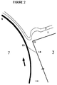
- Figure 2 is a cross-sectional view of the bead region of a conventional slide bead coating apparatus.
- Figure 3 is a view of one embodiment of the present invention showing the orientation of a liquid stripe to the coating solution and apparatus.
- Figure 4 is a view of one embodiment of the present invention showing a nozzle applying a liquid stripe to the substrate.
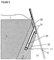
- Figure 5 is a cross-sectional view of the stripe coating region of one embodiment of the present invention.
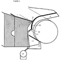
- Figure 6 is a view of one embodiment of the invention which shows the stripes and their relationship to the coating apparatus.
- the liquids to be coated, 1 and 2 flow down the inclined slide surface of the plates, 3 and 4, and traverse a gap, 5, between the closest plate, 3, and the substrate, 6, thereby coating the substrate.
- the substrate, 6, is conveyed by a coating roll, 7.
- Coating liquid is supplied by an appropriate number of supply pumps 8, 9 which feed into cavities 10, 11 and slots 12, 13 in plates 3 and 4.
- Coating additional layers requires additional plates and an appropriate number of pumps, cavities and slots.
- a chamber, 14, and associated pump, 15, controls the gas pressure on the lower surface of the liquid in the gap, 5, such that the pressure at the lower liquid surface is less than the pressure at the upper liquid surface.
- coating liquids 1, 2 flow down the slide surface and over the coater lip tip, 16, to form a continuous liquid bridge between the lip surface, 17, and the substrate, 6.
- the closest distance between the lip tip, 16, and the substrate surface, 6, referred to as the coating gap, 5, is typically 0.1 to 0.5 mm.
- the differential pressure between the gas above the top liquid surface, usually at atmospheric pressure, and the gas below the bottom liquid surface as applied by chamber, 14, draws the liquid bead into the gap between the lip surface, 17, and the substrate, 6.
- Typical pressure differentials of 400 to 4000 dynes/cm2 are applied.
- the applied differential pressure helps produce a stable bead with a spatially-stationary liquid wetting line, or static contact line, 18, on the coater lip surface, 17, and a spatially-stationary liquid wetting line, or dynamic contact line, 19, on the moving substrate, 6.
- Typical substrate speeds are 25 to 300 cm/sec.
- the stripe coater in the Figure 3 embodiment is a nozzle, 22, with a small exit orifice, 23, and associated liquid supply means 24.
- the nozzle, 22, is positioned such that the orifice, 23, is close to the substrate, 6, at a lateral location which allows the edge of the bead, 21, to coalesce with the liquid stripe, 20.
- Figure 3 depicts an embodiment of the present invention for one coating edge of the liquid layer(s). The other coating edge would be similarly stabilized and is not shown here.
- a single coating layer, 1, is depicted for clarity.
- a narrow liquid stripe 20, is first applied to the substrate, 6, via a stripe coater.
- the stripe-bearing substrate then contacts the coating bead, 21, carrying away a liquid film with the layered configuration established on the slide.
- the stripe coater in the Figure 3 embodiment is a nozzle, 22, with a small exit orifice, 23, and associated liquid supply means, 24.
- the nozzle 22, is positioned such that the orifice, 23, is close to the substrate, 6, at a lateral location which allows the edge of the bead, 21, to contact and coalesce with the liquid stripe.
- stripe coating via an orifice located closely to the substrate is preferred. Stripes applied by this method are stable, easily controlled, and easily and precisely positioned.
- the clearance between the nozzle orifice and substrate is 0.05 mm to 0.50 mm, more preferably 0.05 mm to 0.25 mm.
- the liquid stripes are approximately the same thickness (within 25%) as the subsequent nominal coating.
- the coated thickness of the pre-coated stripe is usually .020 mm to .250 mm but more typically is .05 mm to .100 mm thick.
- the subsequent thick edges usually must be removed prior to or during drying or they must be dryed.
- Stripe width is usually 0.1 mm to 10.0 mm, more typically 1.0 mm to 5.0 mm wide. Wider stripes can be beneficial but are less desirable because the additional liquid must eventually be removed. Furthermore, effective stripe positioning becomes difficult as the strip widens since stripe edge stability and contraction of the stripes themselves become problematic.
- the stripe applicator embodiment of the type depicted in Figure 3 is preferably positioned within 100 mm of the coating lip. More preferably, they are positioned within 25 mm.
- stripe application methods that can apply the stripes continuously regardless of the proximity of the strip applicator to the substrate and/or methods that are not as sensitive to the proximity such as with the spray nozzle in Figure 4 are not subject to these preferences as would be obvious to one skilled in the art.
- stripes applied prior to the vacuum chamber structure by one of the alternate means can have potential detrimental interference with the vacuum chamber structure.
- Figure 5 is a cross-section view of a most-preferred embodiment of a stripe application.
- the nozzle, 32 directs a stream of the stripe liquid, 29, toward the moving substrate, 6.
- a liquid inlet, 33 is attached to the nozzle for introduction of the stripe liquid, 29.
- the liquid flows into the open cavity, 30, formed between the nozzle face, 31, and the substrate, 6, and is carried away by the moving substrate.
- the nozzle is conveniently integrated with the coater structure, 3, facilitating precise alignment with coater edges and attainment of precise clearance with the substrate.
- the stripe is coated very close to the edge of the coating bead, stabilizing the coating bead edges substantially before they can become vulnerable to contraction after starting the coating process by bringing the coating head and substrate into functional coating clearance.
- the location of the stripe liquid inlet, 33, with respect to the entire apparatus is shown in Figure 6 for the most-preferred embodiment of Figure 5.
- the inlet is preferably adapted to accept a removable couple from a supply means. Any coupling means known in the art such as a threaded bore, compression fitting, quick snap fittings and the like can be employed. Standard supply means such as a direct hookup to a standard water supply line, a reservoir and pump, or the like, which are suitable.
- a flowmeter is included within the supply means as known in the art.
- the nozzles can be supplied and controlled either individually or in tandem.
- the liquid used for the stripes can be any liquid that will wet the substrate and coalesce with the coating bead. Coalescing of the bead edge with a liquid stripe requires that the two are in contact. A meeting of the edges of both or a slight overlap are usually sufficient contact. Preferably, this coalesce is accomplished by choosing a stripe liquid upon which the coating bead liquid will tend to spread. More preferably, the stripe liquid will also be miscible with the coating bead liquid.
- the film support for the emulsion layers used in the novel process may be any suitable transparent plastic or paper.
- suitable plastics include, but are not limited to, cellulosic supports, e.g. cellulose acetate, cellulose triacetate, cellulose mixed esters, polyethylene terephthalate/isophthalates and the like.
- the above polyester films are particularly suitable because of their dimensional stability.
- a resin subbing layer such as, for example, the mixed-polymer subbing compositions of vinylidene chloride-itaconic acid, taught by Rawlins in U.S. Pat. No. 3,567,452, or antistatic compositions as taught by Miller U.S. Patents 4,916,011 and 4,701,403 and Cho U.S. Patent 4,891,308.
- the coated element of a photographic film is dryed by liquid medium evaporation.
- the evaporation is preferably accelerated by conduction, convection and/or radiation heating.
- Heat transfer can occur through the support such as by physical contact with a heated drum or roller or by direct contact with a gaseous medium such as warm air. Jet impingement of the coated layers with a gaseous medium provides both a heat and mass transfer medium.
- Radiation to which the photographic element is relatively insensitive can be used to facilitate liquid medium evaporation, and microwave heating.
- the reference examples were repeated but with edge stripes coated approximately 20 mm in advance of the coating lip and positioned so that the stripe edge would approximately align with the edge of the edge guide.
- the stripes were coated with tap water at a flow rate of 0.19 cc/sec from 1.6 mm diameter exit holes in small blocks. Clearance between the blocks and the substrate was about 0.25 mm. The resultant channel of water on the substrate was 2-3 mm wide.
- Table 2 lists the critical differential pressures.
- the mode of instability was an excessive stretching of and subsequent disturbance to the coating bead first starting at the central region of the bead width and quickly spreading toward each edge. The disturbance gave the impression of air draw-under and did not appear to be directly associated with the edges in any way.
- the critical differential pressures in Table 2 are significantly reduced relative to corresponding values for the reference examples in Table 1 and that the realized instability mode is not associated with the edges. This means the edges are significantly stabilized by the presence of the coalescing water stripes.
Landscapes
- Chemical & Material Sciences (AREA)
- Engineering & Computer Science (AREA)
- Materials Engineering (AREA)
- Physics & Mathematics (AREA)
- General Physics & Mathematics (AREA)
- Application Of Or Painting With Fluid Materials (AREA)
- Coating Apparatus (AREA)
Applications Claiming Priority (2)
| Application Number | Priority Date | Filing Date | Title |
|---|---|---|---|
| US90535492A | 1992-06-24 | 1992-06-24 | |
| US905354 | 1992-06-24 |
Publications (2)
| Publication Number | Publication Date |
|---|---|
| EP0575879A2 true EP0575879A2 (en) | 1993-12-29 |
| EP0575879A3 EP0575879A3 (enExample) | 1994-03-16 |
Family
ID=25420682
Family Applications (1)
| Application Number | Title | Priority Date | Filing Date |
|---|---|---|---|
| EP93109605A Withdrawn EP0575879A2 (en) | 1992-06-24 | 1993-06-16 | Pretreated substrate for slide bead coating |
Country Status (2)
| Country | Link |
|---|---|
| EP (1) | EP0575879A2 (enExample) |
| JP (1) | JPH0655121A (enExample) |
Cited By (1)
| Publication number | Priority date | Publication date | Assignee | Title |
|---|---|---|---|---|
| US7321058B2 (en) | 2000-06-14 | 2008-01-22 | Basf Aktiengesellschaft | Method for producing acrolein and/or acrylic acid |
Families Citing this family (1)
| Publication number | Priority date | Publication date | Assignee | Title |
|---|---|---|---|---|
| CN102371223A (zh) * | 2010-08-26 | 2012-03-14 | 昆山大阳机电设备制造有限公司 | 涂布机的涂布间隙调整装置 |
Family Cites Families (9)
| Publication number | Priority date | Publication date | Assignee | Title |
|---|---|---|---|---|
| GB1025612A (en) * | 1962-04-07 | 1966-04-14 | Kodak Ltd | Improvements in and relating to coating supports with aqueous compositions |
| US3627564A (en) * | 1970-07-16 | 1971-12-14 | Eastman Kodak Co | Method for coating a continuous web |
| US3749053A (en) * | 1971-11-01 | 1973-07-31 | Polaroid Corp | Coating apparatus |
| JPS5927232B2 (ja) * | 1978-06-26 | 1984-07-04 | 富士写真フイルム株式会社 | 塗布方法 |
| JPS5822266B2 (ja) * | 1978-12-19 | 1983-05-07 | 富士写真フイルム株式会社 | 塗布方法 |
| DE3041721A1 (de) * | 1980-11-05 | 1982-06-09 | Agfa-Gevaert Ag, 5090 Leverkusen | Vorrichtung zum auftragen von mindestens einer schicht auf eine oberflaeche eines gutes |
| JPS61257268A (ja) * | 1985-05-10 | 1986-11-14 | Fuji Photo Film Co Ltd | 塗布方法 |
| JPH0615066B2 (ja) * | 1988-10-14 | 1994-03-02 | 富士写真フイルム株式会社 | 塗布方法 |
| JP2565412B2 (ja) * | 1990-04-12 | 1996-12-18 | 富士写真フイルム株式会社 | 塗布装置 |
-
1993
- 1993-06-16 EP EP93109605A patent/EP0575879A2/en not_active Withdrawn
- 1993-06-24 JP JP15360093A patent/JPH0655121A/ja active Pending
Cited By (1)
| Publication number | Priority date | Publication date | Assignee | Title |
|---|---|---|---|---|
| US7321058B2 (en) | 2000-06-14 | 2008-01-22 | Basf Aktiengesellschaft | Method for producing acrolein and/or acrylic acid |
Also Published As
| Publication number | Publication date |
|---|---|
| JPH0655121A (ja) | 1994-03-01 |
| EP0575879A3 (enExample) | 1994-03-16 |
Similar Documents
| Publication | Publication Date | Title |
|---|---|---|
| US4977852A (en) | Method of simultaneous multilayer application | |
| US5861195A (en) | Method for coating a plurality of fluid layers onto a substrate | |
| US4490418A (en) | Coating method and apparatus | |
| EP0327020B1 (en) | Coating apparatus | |
| EP0261613A1 (en) | Method and apparatus for coating webs | |
| EP0954383B1 (en) | Method for minimizing waste when coating a fluid with a slide coater | |
| US5380365A (en) | Lip surface geometry for slide bead coating | |
| US5849363A (en) | Apparatus and method for minimizing the drying of a coating fluid on a slide coater surface | |
| EP0575879A2 (en) | Pretreated substrate for slide bead coating | |
| US4265941A (en) | Differential pressure coating system | |
| US5332440A (en) | Coating lip geometry for slide bead coating | |
| US5458925A (en) | Dual geometry for slide-bead coating | |
| JPS5837866B2 (ja) | 塗布方法及び装置 | |
| JP2003211048A (ja) | 塗布装置及び塗布方法 | |
| JPS6111173A (ja) | 塗布方法及び塗布装置 | |
| JP3487445B2 (ja) | 塗布方法および装置 | |
| JPS6028851A (ja) | 塗布方法及びその装置 | |
| JP3702620B2 (ja) | カーテン塗布装置及びカーテン塗布方法 | |
| JPH11147061A (ja) | 塗布装置 | |
| JPH054066A (ja) | 塗布装置 | |
| JP2002361148A (ja) | 塗布装置 | |
| JPS6028855A (ja) | 塗布方法 | |
| JPS63287574A (ja) | 塗布方法及び装置 | |
| JPS63239441A (ja) | 塗布方法及びその装置 |
Legal Events
| Date | Code | Title | Description |
|---|---|---|---|
| PUAI | Public reference made under article 153(3) epc to a published international application that has entered the european phase |
Free format text: ORIGINAL CODE: 0009012 |
|
| AK | Designated contracting states |
Kind code of ref document: A2 Designated state(s): BE DE FR IT |
|
| PUAL | Search report despatched |
Free format text: ORIGINAL CODE: 0009013 |
|
| AK | Designated contracting states |
Kind code of ref document: A3 Designated state(s): BE DE FR IT |
|
| 17P | Request for examination filed |
Effective date: 19940615 |
|
| STAA | Information on the status of an ep patent application or granted ep patent |
Free format text: STATUS: THE APPLICATION HAS BEEN WITHDRAWN |
|
| 18W | Application withdrawn |
Withdrawal date: 19950504 |