EP0575763A1 - Roue pour un ventilateur radial - Google Patents
Roue pour un ventilateur radial Download PDFInfo
- Publication number
- EP0575763A1 EP0575763A1 EP93108392A EP93108392A EP0575763A1 EP 0575763 A1 EP0575763 A1 EP 0575763A1 EP 93108392 A EP93108392 A EP 93108392A EP 93108392 A EP93108392 A EP 93108392A EP 0575763 A1 EP0575763 A1 EP 0575763A1
- Authority
- EP
- European Patent Office
- Prior art keywords
- blades
- primary
- guide ring
- impeller
- hub
- Prior art date
- Legal status (The legal status is an assumption and is not a legal conclusion. Google has not performed a legal analysis and makes no representation as to the accuracy of the status listed.)
- Granted
Links
Images


Classifications
-
- F—MECHANICAL ENGINEERING; LIGHTING; HEATING; WEAPONS; BLASTING
- F04—POSITIVE - DISPLACEMENT MACHINES FOR LIQUIDS; PUMPS FOR LIQUIDS OR ELASTIC FLUIDS
- F04D—NON-POSITIVE-DISPLACEMENT PUMPS
- F04D29/00—Details, component parts, or accessories
- F04D29/26—Rotors specially for elastic fluids
- F04D29/28—Rotors specially for elastic fluids for centrifugal or helico-centrifugal pumps for radial-flow or helico-centrifugal pumps
- F04D29/281—Rotors specially for elastic fluids for centrifugal or helico-centrifugal pumps for radial-flow or helico-centrifugal pumps for fans or blowers
-
- F—MECHANICAL ENGINEERING; LIGHTING; HEATING; WEAPONS; BLASTING
- F04—POSITIVE - DISPLACEMENT MACHINES FOR LIQUIDS; PUMPS FOR LIQUIDS OR ELASTIC FLUIDS
- F04D—NON-POSITIVE-DISPLACEMENT PUMPS
- F04D29/00—Details, component parts, or accessories
- F04D29/08—Sealings
- F04D29/16—Sealings between pressure and suction sides
- F04D29/161—Sealings between pressure and suction sides especially adapted for elastic fluid pumps
- F04D29/162—Sealings between pressure and suction sides especially adapted for elastic fluid pumps of a centrifugal flow wheel
-
- F—MECHANICAL ENGINEERING; LIGHTING; HEATING; WEAPONS; BLASTING
- F04—POSITIVE - DISPLACEMENT MACHINES FOR LIQUIDS; PUMPS FOR LIQUIDS OR ELASTIC FLUIDS
- F04D—NON-POSITIVE-DISPLACEMENT PUMPS
- F04D29/00—Details, component parts, or accessories
- F04D29/26—Rotors specially for elastic fluids
- F04D29/28—Rotors specially for elastic fluids for centrifugal or helico-centrifugal pumps for radial-flow or helico-centrifugal pumps
- F04D29/284—Rotors specially for elastic fluids for centrifugal or helico-centrifugal pumps for radial-flow or helico-centrifugal pumps for compressors
- F04D29/285—Rotors specially for elastic fluids for centrifugal or helico-centrifugal pumps for radial-flow or helico-centrifugal pumps for compressors the compressor wheel comprising a pair of rotatable bladed hub portions axially aligned and clamped together
-
- F—MECHANICAL ENGINEERING; LIGHTING; HEATING; WEAPONS; BLASTING
- F04—POSITIVE - DISPLACEMENT MACHINES FOR LIQUIDS; PUMPS FOR LIQUIDS OR ELASTIC FLUIDS
- F04D—NON-POSITIVE-DISPLACEMENT PUMPS
- F04D29/00—Details, component parts, or accessories
- F04D29/26—Rotors specially for elastic fluids
- F04D29/28—Rotors specially for elastic fluids for centrifugal or helico-centrifugal pumps for radial-flow or helico-centrifugal pumps
- F04D29/30—Vanes
Definitions
- the invention relates to an impeller for a radial fan, in particular for handheld power tools or similar power tools driven by an electric motor, of the type defined in the preamble of claim 1.
- High-performance radial fans equipped with such impellers are used for cooling motors and other components in power tools, as well as for extracting dust, chips, grit, drilling cuttings and other processing goods that arise when handling the power tools and are disposed of with the help of the power tools .
- the aim of these impellers is to have a three-dimensionally curved blade surface.
- the three-dimensionally curved blade surfaces have been approximated in a known impeller (DE 41 09 646.0) by three impeller elements connected in series and assembled, the primary part, the intermediate part and the secondary part, the primary and secondary blades being two-dimensionally curved and the intermediate blades are just trained.
- the impeller according to the invention with the characterizing features of claim 1 has the advantage of only low noise at the same high performance values, which is achieved according to the invention that the rotating sound of the fan is shifted into the inaudible range by the large number of secondary blades.
- the number of secondary blades is as large as possible and is only limited by manufacturing and strength considerations. Despite different numbers of blades in the primary and secondary part, such a fan wheel made up of three impeller elements can be optimized in many ways with regard to cost-effective production.
- the number of primary blades is between 6 and 12, depending on the impeller diameter and blade thickness, while the number of secondary blades is chosen to be over 40.
- the primary blades anchored in the hub are arranged side by side, leaving a gap in the circumferential direction of the hub. This enables simple and inexpensive Production of the fan wheel without affecting its performance values.
- the intermediate blades of the intermediate part normally adjoin the blade surfaces of the primary part without gaps, viewed in the flow direction in the axial direction.
- the number of intermediate blades is equal to the number of primary blades.
- the performance values of the fan are not adversely affected, or not appreciably, but considerable advantages are achieved in terms of simpler and therefore more cost-effective production.
- the secondary blades are curved about an axis oriented approximately parallel to the hub axis. In relation to the direction of rotation, the secondary blades can either end curved forward or curved backward.
- the radius of curvature of the secondary blades can also be infinite, so that they run radially.
- the axis of curvature of the primary blades can also be inclined at an angle to the radial, as a result of which the blade leading edge is skewed. This changes the angle of the blade entry tangent from the hub to the end of the primary blades that is remote from the hub, from 30 ° to 50 °, as a result of which a largely shock-free inflow of air into the primary blades is achieved.
- the flow channels are realized by four boundary surfaces, which differ in different types of manufacture and also different fluidic performance values.
- the flow channels are always limited by the sum of the primary, intermediate and secondary blades and a front and rear guide ring.
- the two guide rings cover the total number of blades transversely to the impeller axis on the front and rear side and can be connected to the narrow end faces of the blades or can also be arranged in a fixed manner.
- a seal is associated with the front guide ring, which reliably prevents a short-circuit current from the outlet area of the impeller to its inlet area.
- the seal is preferably designed as a labyrinth seal, which engages with a spatially fixed part in a finger-like manner in a corresponding rotating part formed in one piece on the front guide ring.
- the hub, primary, intermediate and secondary part as well as the front and rear guide ring are manufactured in one piece in different combinations and as separate parts, which are added to the complete impeller.
- an impeller 10 is shown schematically, or the like for a radial fan, a radial fan. is suitable and in particular for radial fans for hand tools or similar power tools driven by an electric motor.
- the impeller 10 is used, for example, for engine cooling, dust extraction or the like.
- the impeller 10 has a hub 12 with blades 11, which sits on a drive shaft 13 in a rotationally fixed manner.
- the impeller 10 is composed of a primary part 14 with primary blades 15, an intermediate part 16 with intermediate blades 17 and a secondary part 18 with secondary blades 19.
- the primary blades 15 of the primary part 14 arranged in the inflow region and the secondary blades 19 of the secondary part 18 located in the outflow region are each curved in two dimensions, while the intermediate blades 17 of the intermediate part 16 located between the primary and secondary parts 14, 18 are flat.
- the primary blades 15 have a radius of curvature R1, the center of which lies in an axis 20 running in the radial direction or parallel to it. As is not shown in more detail, this axis can also be inclined at an acute angle with respect to the radial, so that the leading edge 151 of the primary blades 15 is skewed.
- the blade inlet tangent 21 sketched in FIG. 2 is placed in such a way that it receives the same direction as the incoming relative inflow velocity, which is symbolized in FIG. 2 by an arrow 22.
- the skewing of the blade leading edge 151 takes account of the fact that As the radius increases and the peripheral speed thus increases, the angle of flow of the air along the blade leading edge 151 changes. If the axis of curvature of the primary blades 15 is inclined by a corresponding angle with respect to the radial, the angle ⁇ (FIG. 2) of the blade entry tangent 21 increases from the base of the primary blades 15 on the hub 12 to its free end of 30 ° -50 °, so that the direction of the inflow velocity of the air coincides with the blade entry tangent 21 over the entire length of the blade entry edge 151.
- the number of primary blades 15 is chosen between six and twelve depending on the impeller diameter and blade thickness, the primary blades 15 anchored in the hub 12 standing on a gap.
- the gap l between the blade leading edge 151 of a primary blade 15 and the end part 152 of a primary blade 15 leading in the direction of rotation is shown in FIG. 3.
- the left and right mold halves can be demolded in the purely axial direction during the injection molding of the impeller, which contributes to the inexpensive manufacture of the fan wheel overall. This gap arrangement does not impair the performance values of the fan wheel.
- the intermediate part 16 adjoins the primary part 14 essentially axially and has a number of intermediate blades 17 which is equal to the number of primary blades 15.
- the number of intermediate blades 17 can also be a multiple of the number of primary blades 15.
- the intermediate blades 17 are flat and run in a radial direction, as can be seen in FIG. 3.
- the intermediate blades 17 can also point under one to the radial Extend angles inclined in one or the other circumferential direction.
- the intermediate blades 17 preferably adjoin the primary blades 15 without a gap.
- a more or less wide air gap 23 can also remain between the mutually facing end faces of the primary and intermediate blades 15, 17 for reasons of cost-effective production. The resulting, hardly noticeable performance impairment of the radial fan is more than offset by the manufacturing advantages.
- the secondary part 18 with its two-dimensionally curved secondary blades 19 adjoins the intermediate part 16 essentially in the radial direction.
- the secondary blades 19 are curved around an axis 24 which is aligned parallel to the axis of the hub 12.
- the axis 24 can lie both to the right of the blade surface (as in the exemplary embodiment in FIG. 3) and to the left of the blade surface, so that the secondary blades 19 end curved forward or curved backwards with respect to the direction of rotation ⁇ of the impeller 10. In some cases it is advantageous to make the radius of curvature of the R2 infinite, so that the secondary blades 19 are radially aligned.
- the curvature of the secondary blades 19 is in turn produced by means of a milling cutter, the milling cutter axis being aligned parallel to the hub axis.
- the number of secondary blades 19 is a multiple of the number of primary blades 15.
- the number of blades of the secondary part 18 is chosen to be as large as possible and is only limited by manufacturing and strength aspects. However, the number of secondary blades 19 is preferably greater than forty. Due to this high number of secondary blades 19, the rotary sound of the impeller 10 is in the inaudible range pushed and thus significantly reduces the noise.
- the air flow in these flow channels is indicated in FIG. 1 by the dash-dotted arrow 25.
- all flow channels on the two opposite sides seen in the impeller axis are covered, which is done by means of a front and rear guide ring 26 and 27, which close off all flow channels on the front and rear end faces.
- the front guide ring 26 is fixedly connected to the primary, intermediate and secondary part 14, 16, 18 and rotates with it, while the rear guide ring 27 is spatially fixed and surrounds the drive shaft 13 at a distance is.
- the front guide ring 26 is assigned a labyrinth seal 30, which consists of a part 29 integral with the front guide ring 26 and encircling it and a spatially fixed part 28.
- the two sealing parts 28, 29 engage in one another like fingers and thereby prevent the air flow from being short-circuited from the outlet area to the inflow area.
- the impeller 10 described is composed of two parts.
- the hub 12, the primary part 14, the intermediate part 16 and the secondary part 18 together with the front guide ring 26 and the sealing part 29 of the labyrinth seal 30 located thereon are produced in one piece, for example by injection molding.
- the rear guide ring 27 is produced as a separate part and is attached to the fan housing.
- the exemplary embodiment of an impeller 110 shown in FIG. 5 largely corresponds to the described impeller 10 in terms of flow technology, so that the same components are provided with the same reference numerals.
- the impeller 110 is assembled from three separately manufactured parts.
- the hub 12, the intermediate part 16 with intermediate blades 17, the secondary part 18 with secondary blades 19 and the rear guide ring 27 ' are produced in one piece in a single component.
- the primary part 14 with primary blades 15 and a hub section 121, like the front guide ring 26, form a separate component.
- the three components shown in FIG. 6 in an exploded view are assembled accordingly, the primary blades 15 and the intermediate blades 17 abutting one another seamlessly.
- an impeller 210 is shown in FIG. 7, in which the intermediate blades 17 of the intermediate part 16 are shortened in the axial direction, so that when the three components are joined together, a wide air gap 23 remains between the primary blades 15 and the intermediate blades 17.
- Such a design can be advantageous for demolding the intermediate part 16, secondary part 18 and rear guide ring 27 as a one-piece component.
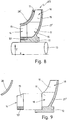
- the third exemplary embodiment of a further impeller 310 shown in detail in longitudinal section in FIG. 8 differs from the ones described above in that the front guide ring 26 'is arranged in a spatially fixed manner, while the rear guide ring 27' rotates with the rotor blades 11 and the hub 12 and is connected to them in a rotationally fixed manner. Otherwise, the further structure is correct with that of the previously described impellers, so that the same components are provided with the same reference numerals.
- the impeller 310 is in turn composed of three separately manufactured components, with the component 14 manufactured as a separate primary part with primary blades 15 being inserted into the other component, as in FIG. 6, which intermediate part 16, secondary part 19, hub 12 and rear guide ring 27 ', which are made in one piece.
- the front guide ring 26 ' which is also produced as a separate component, is attached to the fan housing.
- the fifth exemplary embodiment of an impeller 410 shown in FIG. 10 coincides with the impeller described for FIG. 1 after final assembly.
- the front guide ring 26 is divided in two at the level of the rear end of the intermediate blades 17, seen in the direction of flow, parallel to the impeller axis and consists of an outer ring part 261, which carries part 29 of the labyrinth seal 30, and an inner ring part 262, which extends over the area of the primary blades 15 Hub 11 is manufactured together with the intermediate part 16 and the secondary part 18 and the outer ring part 261 of the front guide ring 26 and the part 29 of the labyrinth seal 30 formed thereon as a one-piece component.
- the inner ring part 262 of the guide ring 26, like the primary part 15 and the rear guide ring 27, is each manufactured as a separate component.
- the one-piece assembly comprising the intermediate part 16, the secondary part 18 and the ring part 262 and the primary part 14 and the inner ring part 262 of the front ring part 26 are joined together and firmly connected to one another.
- the rear guide ring 27 is attached to the fan housing.
Applications Claiming Priority (2)
| Application Number | Priority Date | Filing Date | Title |
|---|---|---|---|
| DE4220227 | 1992-06-20 | ||
| DE4220227A DE4220227A1 (de) | 1992-06-20 | 1992-06-20 | Laufrad für einen Radiallüfter |
Publications (2)
| Publication Number | Publication Date |
|---|---|
| EP0575763A1 true EP0575763A1 (fr) | 1993-12-29 |
| EP0575763B1 EP0575763B1 (fr) | 1997-08-06 |
Family
ID=6461451
Family Applications (1)
| Application Number | Title | Priority Date | Filing Date |
|---|---|---|---|
| EP93108392A Expired - Lifetime EP0575763B1 (fr) | 1992-06-20 | 1993-05-25 | Roue pour un ventilateur radial |
Country Status (2)
| Country | Link |
|---|---|
| EP (1) | EP0575763B1 (fr) |
| DE (2) | DE4220227A1 (fr) |
Cited By (13)
| Publication number | Priority date | Publication date | Assignee | Title |
|---|---|---|---|---|
| FR2724204A1 (fr) * | 1994-09-07 | 1996-03-08 | Behr Gmbh & Co | Ventilateur pour systeme de refroidissement d'un vehicule automobile |
| EP1079114A1 (fr) * | 1998-05-13 | 2001-02-28 | Matsushita Electric Industrial Co., Ltd. | Soufflante electrique et aspirateur comportant ladite soufflante |
| FR2811157A1 (fr) * | 2000-06-30 | 2002-01-04 | Valeo Equip Electr Moteur | Ventilateur a pales de hauteur decroissante pour machine electrique tournante, notamment pour alternateur de vehicule automobile |
| FR2811156A1 (fr) * | 2000-06-30 | 2002-01-04 | Valeo Equip Electr Moteur | Ventilateur pour machine electrique tournante, notamment pour alternateur de vehicule automobile |
| FR2811158A1 (fr) * | 2000-06-30 | 2002-01-04 | Valeo Equip Electr Moteur | Ventilateur a ailettes pour machine electrique tournante, notamment pour alternateur de vehicule automobile |
| WO2002035686A1 (fr) * | 2000-10-23 | 2002-05-02 | Alstom (Switzerland) Ltd. | Moteur electrique a regime eleve |
| WO2004016952A1 (fr) * | 2002-07-26 | 2004-02-26 | Robert Bosch Gmbh | Roue de compresseur |
| FR2890252A1 (fr) * | 2005-08-29 | 2007-03-02 | Electrolux Professionnel Soc P | Appareil electrique de traitement de produits alimentaires dote d'un dispositif de ventilation perfectonne. |
| CN102146930A (zh) * | 2010-02-08 | 2011-08-10 | 山洋电气株式会社 | 电动风扇 |
| RU2449179C1 (ru) * | 2010-12-10 | 2012-04-27 | Закрытое акционерное общество "Научно-исследовательский и конструкторский институт центробежных и роторных компрессоров им. В.Б. Шнеппа" | Рабочее колесо центробежного компрессора |
| RU2450165C1 (ru) * | 2010-12-23 | 2012-05-10 | Закрытое акционерное общество "Научно-исследовательский и конструкторский институт центробежных и роторных компрессоров им. В.Б. Шнеппа" | Рабочее колесо центробежного компрессора |
| RU2615566C1 (ru) * | 2016-04-28 | 2017-04-05 | Акционерное общество "Специальное конструкторское бюро "Турбина" | Рабочее колесо центробежного компрессора |
| CN108757559A (zh) * | 2018-07-04 | 2018-11-06 | 大连派思透平动力科技有限公司 | 一种单级分段式离心压气机叶轮结构 |
Families Citing this family (6)
| Publication number | Priority date | Publication date | Assignee | Title |
|---|---|---|---|---|
| DE4427115C1 (de) * | 1994-07-30 | 1995-04-06 | Braun Ag | Laufrad für ein Radialgebläse |
| US8087977B2 (en) | 2005-05-13 | 2012-01-03 | Black & Decker Inc. | Angle grinder |
| CN102087853B (zh) * | 2010-12-03 | 2012-11-28 | 中国航空规划建设发展有限公司 | 一种航空发动机试车台用元件集合型超低频消声装置 |
| US10818450B2 (en) | 2017-06-14 | 2020-10-27 | Black & Decker Inc. | Paddle switch |
| JP7348831B2 (ja) | 2019-12-20 | 2023-09-21 | 三菱重工コンプレッサ株式会社 | インペラ及び回転機械 |
| JP7453896B2 (ja) * | 2020-11-12 | 2024-03-21 | 三菱重工コンプレッサ株式会社 | 回転機械のインペラ及び回転機械 |
Citations (9)
| Publication number | Priority date | Publication date | Assignee | Title |
|---|---|---|---|---|
| DE197769C (fr) * | 1907-03-26 | 1908-04-25 | ||
| CH98624A (de) * | 1922-01-07 | 1923-04-02 | Oerlikon Maschf | Gebläse. |
| US1926225A (en) * | 1930-09-12 | 1933-09-12 | Birmann Rudolph | Turbo compressor |
| US2301857A (en) * | 1940-01-12 | 1942-11-10 | Buffalo Forge Co | Blower fan |
| CH330608A (de) * | 1953-09-11 | 1958-06-15 | Garrett Corp | Laufschaufelrad für elastische Strömungsmittel |
| FR1471604A (fr) * | 1966-03-10 | 1967-03-03 | Neu Sa | Perfectionnement à la construction de roues fermées de compresseurs centrifuges en alliage léger |
| EP0072177A2 (fr) * | 1981-08-07 | 1983-02-16 | Holset Engineering Company Limited | Rotor pour compresseur centrifuge |
| FR2550585A1 (fr) * | 1983-08-09 | 1985-02-15 | Foueillassar Jean Marie | Moyens d'uniformiser la vitesse d'un fluide a la sortie d'un rouet centrifuge |
| WO1991019906A1 (fr) * | 1990-06-19 | 1991-12-26 | Martin Terence Cole | Aspirateur ou pompe de fluide gazeux |
-
1992
- 1992-06-20 DE DE4220227A patent/DE4220227A1/de not_active Withdrawn
-
1993
- 1993-05-25 EP EP93108392A patent/EP0575763B1/fr not_active Expired - Lifetime
- 1993-05-25 DE DE59307053T patent/DE59307053D1/de not_active Expired - Fee Related
Patent Citations (9)
| Publication number | Priority date | Publication date | Assignee | Title |
|---|---|---|---|---|
| DE197769C (fr) * | 1907-03-26 | 1908-04-25 | ||
| CH98624A (de) * | 1922-01-07 | 1923-04-02 | Oerlikon Maschf | Gebläse. |
| US1926225A (en) * | 1930-09-12 | 1933-09-12 | Birmann Rudolph | Turbo compressor |
| US2301857A (en) * | 1940-01-12 | 1942-11-10 | Buffalo Forge Co | Blower fan |
| CH330608A (de) * | 1953-09-11 | 1958-06-15 | Garrett Corp | Laufschaufelrad für elastische Strömungsmittel |
| FR1471604A (fr) * | 1966-03-10 | 1967-03-03 | Neu Sa | Perfectionnement à la construction de roues fermées de compresseurs centrifuges en alliage léger |
| EP0072177A2 (fr) * | 1981-08-07 | 1983-02-16 | Holset Engineering Company Limited | Rotor pour compresseur centrifuge |
| FR2550585A1 (fr) * | 1983-08-09 | 1985-02-15 | Foueillassar Jean Marie | Moyens d'uniformiser la vitesse d'un fluide a la sortie d'un rouet centrifuge |
| WO1991019906A1 (fr) * | 1990-06-19 | 1991-12-26 | Martin Terence Cole | Aspirateur ou pompe de fluide gazeux |
Cited By (18)
| Publication number | Priority date | Publication date | Assignee | Title |
|---|---|---|---|---|
| FR2724204A1 (fr) * | 1994-09-07 | 1996-03-08 | Behr Gmbh & Co | Ventilateur pour systeme de refroidissement d'un vehicule automobile |
| EP1079114A1 (fr) * | 1998-05-13 | 2001-02-28 | Matsushita Electric Industrial Co., Ltd. | Soufflante electrique et aspirateur comportant ladite soufflante |
| EP1079114A4 (fr) * | 1998-05-13 | 2005-04-13 | Matsushita Electric Ind Co Ltd | Soufflante electrique et aspirateur comportant ladite soufflante |
| FR2811157A1 (fr) * | 2000-06-30 | 2002-01-04 | Valeo Equip Electr Moteur | Ventilateur a pales de hauteur decroissante pour machine electrique tournante, notamment pour alternateur de vehicule automobile |
| FR2811156A1 (fr) * | 2000-06-30 | 2002-01-04 | Valeo Equip Electr Moteur | Ventilateur pour machine electrique tournante, notamment pour alternateur de vehicule automobile |
| FR2811158A1 (fr) * | 2000-06-30 | 2002-01-04 | Valeo Equip Electr Moteur | Ventilateur a ailettes pour machine electrique tournante, notamment pour alternateur de vehicule automobile |
| WO2002035686A1 (fr) * | 2000-10-23 | 2002-05-02 | Alstom (Switzerland) Ltd. | Moteur electrique a regime eleve |
| WO2004016952A1 (fr) * | 2002-07-26 | 2004-02-26 | Robert Bosch Gmbh | Roue de compresseur |
| FR2890252A1 (fr) * | 2005-08-29 | 2007-03-02 | Electrolux Professionnel Soc P | Appareil electrique de traitement de produits alimentaires dote d'un dispositif de ventilation perfectonne. |
| EP1760862A1 (fr) * | 2005-08-29 | 2007-03-07 | Electrolux Professionnel | Appareil électrique de traitement de produits alimentaires doté d'un dispositif de ventilation perfectionné |
| CN102146930A (zh) * | 2010-02-08 | 2011-08-10 | 山洋电气株式会社 | 电动风扇 |
| US20110194955A1 (en) * | 2010-02-08 | 2011-08-11 | Sanyo Denki Co., Ltd. | Electric fan |
| US20140205476A1 (en) * | 2010-02-08 | 2014-07-24 | Sanyo Denki Co., Ltd. | Electric fan |
| US9033680B2 (en) * | 2010-02-08 | 2015-05-19 | Sanyo Denki Co., Ltd. | Electric fan |
| RU2449179C1 (ru) * | 2010-12-10 | 2012-04-27 | Закрытое акционерное общество "Научно-исследовательский и конструкторский институт центробежных и роторных компрессоров им. В.Б. Шнеппа" | Рабочее колесо центробежного компрессора |
| RU2450165C1 (ru) * | 2010-12-23 | 2012-05-10 | Закрытое акционерное общество "Научно-исследовательский и конструкторский институт центробежных и роторных компрессоров им. В.Б. Шнеппа" | Рабочее колесо центробежного компрессора |
| RU2615566C1 (ru) * | 2016-04-28 | 2017-04-05 | Акционерное общество "Специальное конструкторское бюро "Турбина" | Рабочее колесо центробежного компрессора |
| CN108757559A (zh) * | 2018-07-04 | 2018-11-06 | 大连派思透平动力科技有限公司 | 一种单级分段式离心压气机叶轮结构 |
Also Published As
| Publication number | Publication date |
|---|---|
| DE59307053D1 (de) | 1997-09-11 |
| DE4220227A1 (de) | 1993-12-23 |
| EP0575763B1 (fr) | 1997-08-06 |
Similar Documents
| Publication | Publication Date | Title |
|---|---|---|
| EP0575763B1 (fr) | Roue pour un ventilateur radial | |
| EP1649575B1 (fr) | Machine electrique a refroidissement de rotor | |
| EP0574731B1 (fr) | Machine outil à main à moteur ventilé | |
| EP2737189B1 (fr) | Module ventilateur de radiateur | |
| EP2677174A2 (fr) | Roue de ventilateur et moteur électrique | |
| EP2631488B1 (fr) | Pompe à vide | |
| DE19847681C1 (de) | Flüssigkeitsringpumpe | |
| DE102016209312A1 (de) | Elektrische kreiselpumpe | |
| EP2771581B1 (fr) | Roue de ventilateur axial | |
| EP2122181B1 (fr) | Roue de ventilateur, système et série de boîte de vitesses | |
| DE19607573A1 (de) | Kraftstoffpumpe und Verfahren zu ihrer Herstellung | |
| EP2122182B1 (fr) | Roue de ventilateur, système et série de boîte de vitesses | |
| EP1935560A1 (fr) | Meule réfrigérante, système de rectification et outil de rectification | |
| EP4073389A1 (fr) | Roue à aubes pour rotor, et machine électrique | |
| WO1992016753A1 (fr) | Rotor pour une soufflante radiale | |
| EP1292774B1 (fr) | Pompe a canal lateral | |
| EP2253851A2 (fr) | Pompe à vide | |
| DE3514207A1 (de) | Lichtmaschine mit einem luefterrad zum ansaugen von kuehlluft fuer kraftfahrzeuge | |
| DE4234687C2 (de) | Kernloser Drehmomentwandler | |
| EP1212177A1 (fr) | Ensemble d'usinage comprenant un outil rotatif et une hotte d'aspiration | |
| DE4304334A1 (de) | Aggregat zum Fördern von Kraftstoff aus einem Vorratstank zur Brennkraftmaschine eines Kraftfahrzeugs | |
| EP1187991B1 (fr) | Pompe d'alimentation | |
| DE10256805A1 (de) | Elektromotor, insbesondere für Elektrohandwerkzeugmaschinen | |
| EP3641983B1 (fr) | Plateau rotatif comprenant un entraînement optimisé en force | |
| EP0561864A1 (en) | Radial ventilator |
Legal Events
| Date | Code | Title | Description |
|---|---|---|---|
| PUAI | Public reference made under article 153(3) epc to a published international application that has entered the european phase |
Free format text: ORIGINAL CODE: 0009012 |
|
| AK | Designated contracting states |
Kind code of ref document: A1 Designated state(s): CH DE FR GB IT LI |
|
| 17P | Request for examination filed |
Effective date: 19940526 |
|
| 17Q | First examination report despatched |
Effective date: 19950509 |
|
| GRAG | Despatch of communication of intention to grant |
Free format text: ORIGINAL CODE: EPIDOS AGRA |
|
| GRAH | Despatch of communication of intention to grant a patent |
Free format text: ORIGINAL CODE: EPIDOS IGRA |
|
| GRAH | Despatch of communication of intention to grant a patent |
Free format text: ORIGINAL CODE: EPIDOS IGRA |
|
| GRAA | (expected) grant |
Free format text: ORIGINAL CODE: 0009210 |
|
| AK | Designated contracting states |
Kind code of ref document: B1 Designated state(s): CH DE FR GB IT LI |
|
| ET | Fr: translation filed | ||
| REG | Reference to a national code |
Ref country code: CH Ref legal event code: NV Representative=s name: SCINTILLA AG, DIREKTION Ref country code: CH Ref legal event code: EP |
|
| REF | Corresponds to: |
Ref document number: 59307053 Country of ref document: DE Date of ref document: 19970911 |
|
| GBT | Gb: translation of ep patent filed (gb section 77(6)(a)/1977) |
Effective date: 19971008 |
|
| ITF | It: translation for a ep patent filed |
Owner name: STUDIO JAUMANN P. & C. S.N.C. |
|
| PG25 | Lapsed in a contracting state [announced via postgrant information from national office to epo] |
Ref country code: LI Free format text: LAPSE BECAUSE OF NON-PAYMENT OF DUE FEES Effective date: 19980531 Ref country code: CH Free format text: LAPSE BECAUSE OF NON-PAYMENT OF DUE FEES Effective date: 19980531 |
|
| PLBE | No opposition filed within time limit |
Free format text: ORIGINAL CODE: 0009261 |
|
| STAA | Information on the status of an ep patent application or granted ep patent |
Free format text: STATUS: NO OPPOSITION FILED WITHIN TIME LIMIT |
|
| 26N | No opposition filed | ||
| REG | Reference to a national code |
Ref country code: CH Ref legal event code: PL |
|
| REG | Reference to a national code |
Ref country code: GB Ref legal event code: IF02 |
|
| PGFP | Annual fee paid to national office [announced via postgrant information from national office to epo] |
Ref country code: FR Payment date: 20030523 Year of fee payment: 11 |
|
| PG25 | Lapsed in a contracting state [announced via postgrant information from national office to epo] |
Ref country code: FR Free format text: LAPSE BECAUSE OF NON-PAYMENT OF DUE FEES Effective date: 20050131 |
|
| REG | Reference to a national code |
Ref country code: FR Ref legal event code: ST |
|
| PGFP | Annual fee paid to national office [announced via postgrant information from national office to epo] |
Ref country code: GB Payment date: 20050512 Year of fee payment: 13 |
|
| PG25 | Lapsed in a contracting state [announced via postgrant information from national office to epo] |
Ref country code: IT Free format text: LAPSE BECAUSE OF NON-PAYMENT OF DUE FEES Effective date: 20050525 |
|
| PGFP | Annual fee paid to national office [announced via postgrant information from national office to epo] |
Ref country code: DE Payment date: 20050712 Year of fee payment: 13 |
|
| PG25 | Lapsed in a contracting state [announced via postgrant information from national office to epo] |
Ref country code: GB Free format text: LAPSE BECAUSE OF NON-PAYMENT OF DUE FEES Effective date: 20060525 |
|
| PG25 | Lapsed in a contracting state [announced via postgrant information from national office to epo] |
Ref country code: DE Free format text: LAPSE BECAUSE OF NON-PAYMENT OF DUE FEES Effective date: 20061201 |
|
| GBPC | Gb: european patent ceased through non-payment of renewal fee |
Effective date: 20060525 |