EP0575257A2 - Brillenartige Anzeigeapparat - Google Patents
Brillenartige Anzeigeapparat Download PDFInfo
- Publication number
- EP0575257A2 EP0575257A2 EP93401562A EP93401562A EP0575257A2 EP 0575257 A2 EP0575257 A2 EP 0575257A2 EP 93401562 A EP93401562 A EP 93401562A EP 93401562 A EP93401562 A EP 93401562A EP 0575257 A2 EP0575257 A2 EP 0575257A2
- Authority
- EP
- European Patent Office
- Prior art keywords
- lens systems
- display apparatus
- type display
- glasses type
- right lens
- Prior art date
- Legal status (The legal status is an assumption and is not a legal conclusion. Google has not performed a legal analysis and makes no representation as to the accuracy of the status listed.)
- Granted
Links
- 230000007246 mechanism Effects 0.000 claims abstract description 38
- 210000005252 bulbus oculi Anatomy 0.000 claims abstract description 35
- 239000011521 glass Substances 0.000 claims description 93
- 210000003128 head Anatomy 0.000 claims description 52
- 210000001508 eye Anatomy 0.000 claims description 35
- 230000003287 optical effect Effects 0.000 claims description 27
- 230000033001 locomotion Effects 0.000 claims description 17
- 238000000926 separation method Methods 0.000 abstract 1
- 210000000695 crystalline len Anatomy 0.000 description 114
- 210000001747 pupil Anatomy 0.000 description 35
- 239000004973 liquid crystal related substance Substances 0.000 description 34
- 230000010287 polarization Effects 0.000 description 26
- 241001482320 Trachemys Species 0.000 description 19
- 238000010276 construction Methods 0.000 description 18
- 238000010586 diagram Methods 0.000 description 11
- 230000000007 visual effect Effects 0.000 description 9
- 230000004438 eyesight Effects 0.000 description 5
- 230000000694 effects Effects 0.000 description 4
- 241001482322 Trachemys scripta Species 0.000 description 3
- 230000008033 biological extinction Effects 0.000 description 3
- 238000006243 chemical reaction Methods 0.000 description 2
- 208000037265 diseases, disorders, signs and symptoms Diseases 0.000 description 2
- 208000035475 disorder Diseases 0.000 description 2
- 239000000463 material Substances 0.000 description 2
- 229920003023 plastic Polymers 0.000 description 2
- 201000009487 Amblyopia Diseases 0.000 description 1
- 206010019233 Headaches Diseases 0.000 description 1
- 239000000853 adhesive Substances 0.000 description 1
- 230000001070 adhesive effect Effects 0.000 description 1
- 230000004075 alteration Effects 0.000 description 1
- 230000000903 blocking effect Effects 0.000 description 1
- 239000013078 crystal Substances 0.000 description 1
- 238000006073 displacement reaction Methods 0.000 description 1
- 208000002173 dizziness Diseases 0.000 description 1
- 210000001061 forehead Anatomy 0.000 description 1
- 231100000869 headache Toxicity 0.000 description 1
- 229910052751 metal Inorganic materials 0.000 description 1
- 239000002184 metal Substances 0.000 description 1
- 150000002739 metals Chemical class 0.000 description 1
- 238000000465 moulding Methods 0.000 description 1
- 238000010422 painting Methods 0.000 description 1
- 244000144985 peep Species 0.000 description 1
- 230000002093 peripheral effect Effects 0.000 description 1
Images


Classifications
-
- G—PHYSICS
- G02—OPTICS
- G02B—OPTICAL ELEMENTS, SYSTEMS OR APPARATUS
- G02B27/00—Optical systems or apparatus not provided for by any of the groups G02B1/00 - G02B26/00, G02B30/00
- G02B27/01—Head-up displays
- G02B27/017—Head mounted
- G02B27/0176—Head mounted characterised by mechanical features
-
- G—PHYSICS
- G02—OPTICS
- G02B—OPTICAL ELEMENTS, SYSTEMS OR APPARATUS
- G02B27/00—Optical systems or apparatus not provided for by any of the groups G02B1/00 - G02B26/00, G02B30/00
- G02B27/01—Head-up displays
- G02B27/017—Head mounted
-
- G—PHYSICS
- G02—OPTICS
- G02B—OPTICAL ELEMENTS, SYSTEMS OR APPARATUS
- G02B27/00—Optical systems or apparatus not provided for by any of the groups G02B1/00 - G02B26/00, G02B30/00
- G02B27/01—Head-up displays
- G02B27/017—Head mounted
- G02B27/0172—Head mounted characterised by optical features
-
- G—PHYSICS
- G02—OPTICS
- G02B—OPTICAL ELEMENTS, SYSTEMS OR APPARATUS
- G02B7/00—Mountings, adjusting means, or light-tight connections, for optical elements
- G02B7/02—Mountings, adjusting means, or light-tight connections, for optical elements for lenses
- G02B7/12—Adjusting pupillary distance of binocular pairs
-
- H—ELECTRICITY
- H04—ELECTRIC COMMUNICATION TECHNIQUE
- H04N—PICTORIAL COMMUNICATION, e.g. TELEVISION
- H04N13/00—Stereoscopic video systems; Multi-view video systems; Details thereof
- H04N13/30—Image reproducers
- H04N13/332—Displays for viewing with the aid of special glasses or head-mounted displays [HMD]
- H04N13/344—Displays for viewing with the aid of special glasses or head-mounted displays [HMD] with head-mounted left-right displays
-
- H—ELECTRICITY
- H04—ELECTRIC COMMUNICATION TECHNIQUE
- H04N—PICTORIAL COMMUNICATION, e.g. TELEVISION
- H04N13/00—Stereoscopic video systems; Multi-view video systems; Details thereof
- H04N13/30—Image reproducers
- H04N13/398—Synchronisation thereof; Control thereof
-
- G—PHYSICS
- G02—OPTICS
- G02B—OPTICAL ELEMENTS, SYSTEMS OR APPARATUS
- G02B27/00—Optical systems or apparatus not provided for by any of the groups G02B1/00 - G02B26/00, G02B30/00
- G02B27/01—Head-up displays
- G02B27/0101—Head-up displays characterised by optical features
- G02B2027/0132—Head-up displays characterised by optical features comprising binocular systems
-
- G—PHYSICS
- G02—OPTICS
- G02B—OPTICAL ELEMENTS, SYSTEMS OR APPARATUS
- G02B27/00—Optical systems or apparatus not provided for by any of the groups G02B1/00 - G02B26/00, G02B30/00
- G02B27/01—Head-up displays
- G02B27/0149—Head-up displays characterised by mechanical features
- G02B2027/0154—Head-up displays characterised by mechanical features with movable elements
- G02B2027/0156—Head-up displays characterised by mechanical features with movable elements with optionally usable elements
-
- G—PHYSICS
- G02—OPTICS
- G02B—OPTICAL ELEMENTS, SYSTEMS OR APPARATUS
- G02B27/00—Optical systems or apparatus not provided for by any of the groups G02B1/00 - G02B26/00, G02B30/00
- G02B27/01—Head-up displays
- G02B27/0149—Head-up displays characterised by mechanical features
- G02B2027/0154—Head-up displays characterised by mechanical features with movable elements
- G02B2027/0159—Head-up displays characterised by mechanical features with movable elements with mechanical means other than scaning means for positioning the whole image
-
- G—PHYSICS
- G02—OPTICS
- G02B—OPTICAL ELEMENTS, SYSTEMS OR APPARATUS
- G02B27/00—Optical systems or apparatus not provided for by any of the groups G02B1/00 - G02B26/00, G02B30/00
- G02B27/01—Head-up displays
- G02B27/017—Head mounted
- G02B2027/0178—Eyeglass type
-
- G—PHYSICS
- G02—OPTICS
- G02B—OPTICAL ELEMENTS, SYSTEMS OR APPARATUS
- G02B5/00—Optical elements other than lenses
- G02B5/30—Polarising elements
-
- H—ELECTRICITY
- H04—ELECTRIC COMMUNICATION TECHNIQUE
- H04N—PICTORIAL COMMUNICATION, e.g. TELEVISION
- H04N13/00—Stereoscopic video systems; Multi-view video systems; Details thereof
- H04N13/20—Image signal generators
- H04N13/286—Image signal generators having separate monoscopic and stereoscopic modes
Definitions
- This invention relates to a spectacle type display apparatus, which displays a picture formed by computer graphics or the like, so that the user experiences a realization (the so-called virtual reality), as if existing in virtual region in a virtual image.
- the spectacles type display apparatus which is also termed head mounted display etc., has right and left display portions displaying left and right pictures respectively, so that the user sees through left and right lens systems a virtual image synthesized with pictures of these left and right display portions.
- a convex lens P6 which is composed of a plurality of lenses in actual practice, and a light-transmission-type liquid crystal display P7 is supported in front of the convex lens P6 by a supporting device P8 together with the convex lens P6 to thereby display a video image on a display screen P9 of the liquid crystal display P7.
- the liquid crystal display P7 is disposed within a focal length F of the convex lens P6.
- an eye P5 is distant from the convex lens P6 by a distance of 10 to 30 [mm] in the opposite side of the transmission-type liquid crystal display P7.
- the transmission-type liquid crystal display P7 is disposed within the focal length F of the convex lens P6 so that, when the viewer peeps a video image on the display screen P9 of the transmission-type liquid crystal display P7 from the eye P5 side through the convex lens P6 by an illuminated natural light or guided light P10, the viewer can watch a virtual image P4 in the enlarged form at the position distant from the actual position in which the video image is displayed on the display screen P9.
- Fig. 2 is a plan view of the optical system of Fig. 1.
- left and right convex lenses P6L and P6R for magnification are respectively disposed between left and right eyes P5L, P5R and left and right transmission-type liquid crystal displays P7L, P7R, whereby video images displayed on the left and right transmission-type liquid crystal displays P7L, P7R are magnified and also stereoscopic virtual images are displayed on left and right virtual image planes P4L, P4R, respectively.
- the left and right convex lenses P6L, P6R are located very close to the left and right eyes P5L, P5R. Thereby, when the viewer wears the virtual image display of this arrangement, the viewer cannot see the view of the surroundings without taking off such virtual image display device, which is very dangerous.
- FIG. 3 is a schematic diagram used to explain an example such that the video images displayed on the left and right virtual image planes P4L, P4R are displaced in position.
- the virtual image plane P4L is for the left eye and the virtual image plane P4R is for the right eye, and a predetermined point PAL on the virtual image plane P4L viewed by the left eye P5L and a predetermined point PAR on the virtual image plane P4R viewed by the right eye P5R should have been displayed at the same position, inherently.
- a visibility adjusting means has provided in the spectacles type display apparatus.
- This adjustment of visibility is ordinarily performed to bring near to or to keep apart from left and right display portions with respect to the left and right lens systems.
- the left and right display portions are provided on a single moving member to move together. Therefore, when adjusting a visibility, positions of a virtual images GL, GR are moved as shown in Fig. 4, whereupon the positions of the virtual images GL and GR cease to coincide with each other.
- a distance between the left and right lens systems must be adjusted corresponding to various distances between pupils, these being different among users.
- a distance measuring instrument such as a slide caliper and a ruler etc.
- the so-called goggle type construction as shown in Fig. 5A is ordinarily used.
- a space for inserting a pair of glasses within the goggle is provided, to allow for the user wearing glasses for correcting eyesight.
- the user when exchanging the glasses, the user must take off the spectacle type display apparatus of goggle type construction every time, which is very troublesome.
- the spectacle type display apparatus of goggle type construction because visual fields of the outside of the display portion is obstructed by a case, it is difficult and dangerous for example, to walk with the spectacle type display apparatus. Further, the user cannot see other displays while working. Accordingly, if the user wants to see the other displays, the user must remove his own, and there thus arises a problem in that work efficiency is lowered.
- an object of this invention is to provide a spectacle type display apparatus in which positions of left and right virtual images to be seen are coincided so as to improve the user's convenience in particular, even when adjusting a visibility and distance between pupils.
- a spectacle type display apparatus for seeing virtual images obtained through the left and right lens systems 2L, 2R, as shown in Fig. 10, in which: left and right display portions 1R are provided; left and right lens systems 2L, 2R are respectively provided with respect to pictures displayed on the left and right display portions 1L, 1R: the spectacle type display apparatus being such that the left and right lens systems 2L, 2R are moved symmetrically according to a distance between pupils of the user; the left and right display portions 1L, 1R are respectively moved, on a main point axis of the left and right lens systems 2L, 2R and on a segment line FO through a center point O of the left and right lens systems 2L, 2R and a focus F of the left and right lens systems 2L, 2R; and the segment lines FO are moved symmetrically with linkage to motions of the left and right lens systems 2L, 2R, so that the positions of the left and right virtual images to be seen are coincided, regardless of
- the spectacle type display apparatus for seeing virtual images through the left and right lens systems 2L, 2R, comprises: left and right display portions 1L, 1R; the left and right lens systems 2L, 2R being respectively provided with respect to images displayed on the left and right display portions 1L, 1R and further comprises: moving mechanisms 19L, 19R and 42L, 42R for moving symmetrically the left and right lens systems 2L, 2R according to the distance between pupils; left and right sliding mechanisms 29L, 29R and 41L, 41R for sliding along the segment line FO through the center point O of left and right lens mechanisms 2L, 2R and the focus F of the left and right lens systems 2L, 2R, on the main point axis of the left and right lens systems 2L, 2R; linking mechanisms 36L, 36R, 38L, 38R and 39L, 39R for linking with the moving mechanisms 19L, 19R and 42L, 42R of the left and right lens systems 2L, 2R to open and shut symmetrically toward left and right so that left and right sliding mechanisms 29L
- pupil distance scale means 55 and 56 for displaying the distance between pupils corresponding to symmetric movement of the left and right lens systems 2L, 2R, are provided; virtual image display position scale means 62 and 64 for displaying display positions of the virtual image, corresponding to movement of the left and right display portions 1L, 1R on the segment line FO through the center point O of the left and right lens systems 2L, 2R and the focus F of the left and right lens systems 2L, 2R are also provided.
- an image display portion 71 located at the left and right display portions 1L, 1R and the left and right lens systems 2L, 2R are held rotatably around eyeballs as seen from the side of the user; head fitting means 72 to 78 for holding movably in front and behind the image display portion 71 are provided: the head fitting means 72 to 78 holds the image display portion 71 resiliently up above the user's eyes: head fitting means 72 to 78 has weights 76 to 78 corresponding to the weight of the image display portion 71 behind the head.
- the distance between pupils and visibility can be adjusted, and regardless of these adjustment, the positions of the left and right virtual images to be seen can be coincided, even when the distance between the left and right display portions 1L, 1R and the left and right lens systems 2L, 2R, are changed whereupon the spectacle type display apparatus can be used for viewing good quality images by general users.
- the virtual image display position corresponding to adjusted distance between pupils and visibility is indicated on a scale to be checked from the outside.
- the head fitting means 72 to 75 is so constructed that the image display portion 71 can rotate at the temple and the center of eyeballs, so that the user can see images at a natural position. Further, whole image display portion 71 is capable of springing up, so as not to obstruct the viewing at an outside scene if needs be. Furthermore, the weights 76 to 78 are provided behind the head, so that burden to the user's head is reduced.
- Another object of this invention is to provide a spectacle type display apparatus in which an adjustment of the visibility can be accurately achieved with a simple construction, and the outside scene can be seen if necessary.
- the spectacle type display apparatus For solving this problem, the spectacle type display apparatus according to another aspect of the invention; the left and right display portions 1L, 1R produce; virtual images viewed through the left and right lens systems 2L, 2R: the left and right display portions 1L, 1R are respectively moved, on the main point axis and the segment line through the center point of the left and right lens systems 2L, 2R and the focus of the left and right lens systems 2L, 2R; positions of the left and right virtual images to be viewed are coincided, even if the distance between the left and right display portions 1L, 1R and the left and right lens systems 2L, 2R are changed with visibility adjustment.
- the left and right display portions 1L, 1R and the left and right lens systems 2L, 2R are respectively provided with respect to the images displayed on the left and right display portions 1L, 1R; virtual image obtained through the left and right lenses systems are seen, wherein: the sliding mechanisms 13L, 13R and 14L, 14R for sliding along the segment lines through the center point of the left and right lens systems 2L, 2R and the focus of the left and right lens systems 2L, 2R, on the main point axis of the left and right lens systems 2L, 2R, are provided; the left and right display portions 1L, 1R are respectively attached to the left and right sliding mechanisms 13L, 13R and 14L, 14R; the left and right display portions 1L, 1R are respectively moved on the segment lines; the positions of the left and right virtual images to be seen are coincided, even if the distance between the left and right display portions 1L, 1R and the left and the right lens systems 2L, 2R are changed with visibility adjustment.
- the head fitting means for fitting the left and right display portions 1L, 1R and the lens systems 2L, 2R are above the viewer's eyes; the beam splitter 3 is located in front of the viewer's eyes with a slant of 45 [deg] with respect to optical axes of the left and right lens systems 2L, 2R, and extinction means 4 are located in front of the beam splitter 3.
- Embodiments of the invention may include head fitting means 6 for fitting the left and right display portions 1L, 1R and the left and right lens systems 2L, 2R above the viewer's eyes; the beam splitter 3 being located in front of the viewer's eyes with a slant of 45 [deg] with respect to optical axes of the left and right lens systems 2L, 2R; and shutter means 16, 17 and 18 are located in front and/or behind of the beam splitter 3, for shutting only the outside scene in an display area of the virtual image.
- the head fitting member 6 may have a brim 7; the beam splitter 3 is then located beneath the brim 7 and distant from the viewer's face by predetermined distance; the bottom of the beam splitter is covered with a bottom face 5A extending to the enclosure 5; the bottom face 5A extending to the enclosure 5 is to be coincided with eye direction of the viewer's eyes.
- the left and right display portions 1L, 1R are respectively attached to the left and right sliding mechanisms 13L, 13R and 14L, 14R which slide along the segment lines through the center point and the focus of the left and right lens systems 2L, 2R, on the main point axis of the left and right lens systems 2L, 2R; the left and right display portions 1L, 1R are respectively moved on the segment line, and thus, the positions of the left and right virtual images to be seen are coincided, even if the distance between the left and right display portions 1L, 1R and the left and right lens systems 2L, 2R are changed with visibility adjustment.
- the left and right display portions 1L, 1R and the left and right lens systems 2L, 2R are fitted above the viewer's eyes, and thus, the spectacles can be exchanged between users; the distinction means 4 and the shutter means 16, 17 and 18 are so provided that the lower scene of the view field and outside scene of the virtual image display area are obtained, whereupon it is possible that user can walk in it and can see other display or the like working, if necessary.
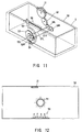
- Fig. 6 generally shows an exterior of the glasses type display apparatus of this invention
- Fig. 7 shows its optical system
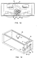
- Fig. 8 shows the arrangement of the mechanisms
- Fig. 9 illustrates an exterior of the mechanisms.
- the left and right lens systems 2L, 2R are respectively provided corresponding to left and right display portions 1L, 1R which are respectively combined with a back light and a liquid crystal display panel.
- Optical axes of these lens systems 2L, 2R are refracted by a beam splitter 3 with a slant of 45 [deg], and is entered to the user's left and right eyeballs.
- a liquid crystal shutter 4 is placed as an extinction means in front of the beam splitter 3.
- the left and right display portions 1L, 1R, the left and right lens systems 2L, 2R, the beam splitter 3 and the liquid crystal shutter 4, are constructed in any enclosure 5.
- This enclosure 5, the inside of which is made of a material, painted frosted black and intercepting light, is provided to a holder table 7 in front of a head fitting member 6. The user wearing this head fitting member 6 on his head can see a virtual image.
- the left and right display portions 1L, 1R, and the left and right lens systems 2L, 2R are provided on the upper side of the holder table 7, and the beam splitter 3 and the liquid crystal shutter 4 are provided on the lower side of it.
- Fig. 6 a case on the upper side of the holder table 7, and the outside portions of the glasses type display apparatus are omitted.
- the left and right display portions 1L, 1R are fixed to linear sliders 11L and 11R as shown in Fig. 8. These linear sliders 11L and 11R are attached to a common slider shaft 12, so that the left and the right display portions 1L, 1R moves left and right. Note that pins 19L and 19R connected to link mechanisms respectively are provided to the linear sliders 11L and 11R.
- the left and right display portions 1L, 1R, the linear sliders 11L and 11R and the slider shaft 12, are moved up or down as whole by the slider shaft 13.
- a dial 14 for visibility adjustment is provided at the center of the left and right display portions 1L, 1R.
- This dial 14 has a screw structure and effects upward or downward movement on the left and right display portions 1L, 1R, the linear sliders 11L, 11R and the slider shaft 12 as a whole with respect to the enclosure 5.
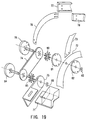
- the lens systems 2L and 2R are respectively fixed to the linear sliders 21L and 21R. These linear sliders 21L and 21R are attached to a common slider shaft 22, in order to move left or right the left and right lens systems 2L, 2R.
- the slider shaft 22 is fixed to the enclosure 5, and the left and right lens systems 2L, 2R, the linear sliders 21L and 21R and the slider shaft 22, are fixed unmovably as a whole in the up or down direction with respect to the enclosure 5.
- vertical grooves 29L and 29R are connected to link mechanisms are respectively provided.
- a dial 31 for controlling a distance between pupils is located to the top of center of the enclosure 5.
- a rotation of a gear 32 which is placed at the same shaft of this dial 31, is transmitted to drive gears 34L and 34R via a semicircular gear 33.
- These drive gears 34L and 34R engage each other, so as to rotatably move in inverse direction. Segment gears 35L and 35R are respectively engaged with this drive gears 34L and 34R.
- first slide arms 36L and 36R are provided to the segment gears 35L and 35R in one body.
- One end of this slide arms 36L and 36R is supported rotatably to a common rotary shaft 37.
- the center portion of this slide arms 36L and 36R are respectively linked to the center portion of the second slide arms 39L and 39R via joining plates 38L and 38R.
- one end of these slide arms 39L and 39R is respectively supported rotatably to rotary shafts 40L and 40R.
- Slide pins 41L and 41R are respectively provided to the other end of this slide arms 39L and 39R, and are inserted into vertical grooves 29L and 29R which are provided in the linear sliders 21L and 21R as shown in Fig. 8.
- Long holes 42L and 42R are provided to the other ends of the slide arms 36L and 36R by the base line, to insert pins 19L and 19R provided to the linear sliders 11L and 11R.
- the display portions 1L, 1R, the linear sliders 11L, 11R and the slider shaft 12 are moved up or down as a whole with respect to the enclosure 5.
- the lens systems 2L, 2R, the linear sliders 21L, 21R and the slider shaft 22 are fixed to the upper and lower portions of the enclosure 5, so that the left and right display portions 1L, 1R and the left and right lens systems 2L, 2R are displaced near to or a part from each other so that the visibility can be adjusted.
- the left and right lens systems 2L, 2R move symmetrically according to the distance between pupils, and then the left and right display portions 1L, 1R move on segment lines OF through a center point O on the main point axis of the left and right lens systems 2L, 2R, and the focus F of the respective lens systems 2L and 2R.
- Fig. 10 denotes an optical arrangement of the left and right display portions 1L, 1R, and the left and right lens systems 2L, 2R. Note that, a practical optical path is refracted by the beam splitter 3. However, in Fig. 10, the beam splitter 3 is omitted. In Fig. 10, for example, when placing a right display portion 1R at a point A, the center of a virtual image obtained as a result is formed at a point B on the optical axis of the right lens system 2R. In practice, in order to coincide with left and right virtual images, it is necessary to move the center of the virtual images at a point C. That is, if the distance between optical axes of the lens systems 2L and 2R are , it may be moved by /2.
- Fig. 10 there is the segment line FO between the focus F and the center point O on the main point axis of the left and right lens systems 2L, 2R. This is similar to the left display portion 1L and the left lens system 2L.
- the slider shafts 12 and 13 are provided to move the left and right display portions 1L, 1R along these segment lines FO, so that positions to see the left and right virtual images are coincided each other, even after changing the distance between the left and right display portions 1L, 1R, and the left and right lens systems 2L, 2R, by dialing the dial 31.
- the left and right lens systems 2L, 2R move symmetrically in the direction near to or part from the center point O along the main point axis . Therefore, the position of the focus F also moves in parallel with the main point axis .
- the base lines of the slide arms 36L and 36R are also rotated to pass on the focuses of respective lens systems 2L, 2R, so that positions of the left and right virtual images to be seen are coincided with a center axis which is orthogonal with the main point axis and passes the center point O.
- the glasses type display apparatus can be realized such that the distance between pupils can be adjusted, and positions of the left and right virtual images to be seen can be coincided each other, even after changing distances between the left and right display portions 1L, 1R, and the left and right lens systems 2L, 2R, by adjusting the distance between pupils, so that a virtual image can be seen properly by all users.
- the adjusted distance between pupils can be displayed on a scale.
- the dial 31 is rotated to adjust the distance between pupils
- the semicircular gear 33 is rotated via the gear 32 fixed by the same axis, and thus this semicircular gear 33 and the drive gears 34L and 34R are rotated.
- Drive gears 52L and 52R attached with a rear chassis of the enclosure 5 are driven by rotation of this drive gears 34L and 34R via shafts 51L and 51R.
- a segment gear 54 is rotated via a synchronization gear 53 fixed to one of drive gear 52L by same axis.
- a scale indicating member 55 fixed to this segment gear 54 is moved to left or right.
- an end of the scale indicating member 55 projects slightly, from a long groove which is formed with the scale of distance between pupils 56 on the outside of the case 50, and moves to left or right by this long groove, so that the user can read the distance between pupils adjusted by rotation of the dial 31 for adjustment of the distance between pupils from the outside, for example, as numerical values 56 to 76 [mm].
- the position of the virtual image corresponding to the adjusted visibility can be displayed on the scale of the virtual image display position. That is, when rotating the dial 14 for position adjustment of the virtual image, the distance between the left and right display portions 1L, 1R and the left and right lens systems 2L, 2R are changed, so that the positions of virtual images displayed in front of the user are changed.
- an attach plate 60 of the left and right display portions 1L, 1R, and a scale side plate 61 attached by screws to this attach plate 60 are moved down.
- a virtual image position indicating plate 62 is connected to a center of scale member 63 and the scale side plate 61 respectively where is attached to a rear chassis 60A by connecting units 62A and 62B, and it can be rotated.
- the virtual image position indicating board 62 rotates at the same time around the center of scale member 63, thus the scale indicating board moves up or down.
- An end portion of this scale indicating board can be seen from the outside through a long groove formed on the outside of the case 50 with the scale of virtual image p0 p0- position 64, to magnify slight amount of adjustment of the dial 14 for position adjustment of virtual image by any time, so that the adjusted position of the virtual image can be easily read from the outside, for example, as numerical values 0.21 to [mm].
- the distance between lenses adjusted is indicated on a scale to check from the outside, by interlocking with a mechanism through variable arrangements of the display portions 1L and 1R and the lens systems 2L and 2R corresponding to the distance between pupils, so that any user can be adjusted accurately with respect to the distance between pupils and a distance between optical axes and the lens systems 2L and 2R.
- a mechanism through variable arrangements of the display portions 1L and 1R and the lens systems 2L and 2R corresponding to the distance between pupils, so that any user can be adjusted accurately with respect to the distance between pupils and a distance between optical axes and the lens systems 2L and 2R.
- the set virtual image display position is indicated on a scale to check from the outside, so as to change the position of the virtual image. Therefore everyone can adjuste accurately to the position of the image that he wants to see.
- the glasses type display apparatus which the user's convenience can be improved in particular.
- Fig. 16 shows a general configuration of head fitting member of the glasses type display apparatus of this invention, in which a weight balance portion is added to the configuration of Fig. 6.
- This glasses type display apparatus is consisted of an image display portion 71 described above with regard to Figs. 6 to 10, an image display portion support members 74 and 75, a head fitting members 72 and 73 and a weight balance portions 76, 77 and 78.
- a periphery fixing band 72 fixes the glasses type display apparatus on the user's head, and its girth is variable correspond to a size and a shape of the user's head.
- a weight supporting band 73 is so provided that the glasses type display apparatus does not fall.
- a mechanism supporting arm 74 is placed at the temple of the head fitting member 72 and is connected to the latter rotatably for up or down movement. As shown in Fig. 17A, this mechanism supporting arm 74 can be sprung up so as not to obstruct when viewing the outside scene. Further, the image display portion supporting arm 75 is connected to the mechanism supporting arm 74 at the opposite side of the head fitting member 72.
- the image display portion supporting arm 75 is rotatable up or down around the rotation center coincided with a central eyeball looking from the side direction.
- the image display portion 71 is constructed to move forward or backward.
- this mechanism supporting arm 74 is rotated to a position where the rotation center of the image display portion supporting arm 75 is brought up or down to coincide with the central eyeball. And then the image display portions supporting arm 75 is rotated, so that the image display apparatus 71 moves up or down around the eyeball as shown in Fig. 17C.
- the display position of the image can be rotated around the eyeball to keep a distance from the user's eyes to the image constant. Keeping the distance constant , images of the display portions 1L and 1R and the virtual image become orthogonal to the user's eyesight; therefore a distortion of shape of the image can be minimized. Further, the angle of the display portions can be easily set 0 to -30 [deg] to the horizontal face, this angle being sonsidered as the most suitable for seeing images; therefore the user's convenience can be improved.
- the weight balance members 76, 77 and 78 consist of a weight arm 76, a balance weight 77 and a weight cover 78. This weight balance members 76, 77 and 78 are constructed to move together with the mechanism supporting arm 74.
- the peripheral fixing band 72 and the weight supporting band 73 are held by a band and receive 81 and a temple guard 82.
- a temple spring 80 is held between this portion and the system supporting arm 74, and is fixed by passing a temple shaft 79 and stopping them with a temple stopping ring 83.
- an eyeball center spring 85 is held between the mechanism supporting arm 74 and a image portion supporting arm 75, and is passed by an eyeball center shaft 84 and an eyeball center stopping ring 86 stops the shaft.
- an eyeball center shaft 84 In a connecting portion of a image portion supporting arm 75 and an image display portion 71, long holes are respectively provided on arm 75 and portion 71, the long holes being connected by a screw to each other. Thereby, the image display portion 71 can be slide forward or backward, and left or right.
- the weight arm 76 are held by the balance weight 77 and the weight cover 78.
- the weight arm 76 has long holes, which allow the weight arm 76 to enlarge in length corresponding to the width of the user's head.
- the image display portion is rotated around the center of an eyeball to allow viewing of a natural image without distortion, and the image display portion is moved forward or backward to be able to allow a viewer to wear it without taking off his glasses.
- the image display portion 71 and the image display portion supporting arm 75 can be sprung up to see easily the outside scene. Further, a weight corresponding to the weight of the image display portion and the girth of the user's head is provided, so as not to tire the wearer by balancing the burden imposed on his head.
- the glasses type display apparatus is also improved as concerns convenience.
- the enclosure is consisted of sheet metals. However, instead of this, it may be constructed by resinous molding etc.. In this case, it may be realized similar to effects to the above embodiments. Further, in the above embodiments the slide arm is connected using drive gears. However, this invention is not only limited to this, and a timing belt or the like may be used instead.
- the dial for adjustment of visibility and for adjustment of a distance between pupils is moved with handle.
- This invention is not only limited to this, but also it may be automatically controlled by mounting drive motor.
- there may be also performed to feedback position data of the display portion, which is calculated as a position of the virtual image from image data.
- a scale is indicated by rotating the indicating board to read this.
- This invention is not only limited to this, but also the motion of the indicating board may be converted into the straight-line motion by using mechanism such as rack, pinion or the like.
- Rotary angles of a gear read by such rotary encoder may also be displayed on a display portion composed of such as liquid crystal.
- movable portions, such as a link, of the adjustment mechanism may be used as a scale, to produce effects similar to these of the above embodiments.
- the spring for connecting portion of the head fitting member is used.
- this invention is not only limited to this, and a coil spring may also be used, and a motor may be mounted instead of the spring.
- a helmet and a cap or the like may be used, instead of the band for head fitting.
- this invention is applied to the glasses type display apparatus for virtual reality.
- this invention is not only limited to this, but also this invention may be suitable applied widely to various kinds of a display apparatus, such as a computer display apparatus or the like.
- the glasses type display apparatus can be realized, in which an adjustment of distance between pupils and a visibility adjustment can be executed, and regardless of this adjustment, even if changing a distance between the left and right display portions and the lens systems, positions of the left and right virtual images can be coincided each other, so that every user can see clear images. Further, the virtual image display position corresponding to adjusted distance between pupils and visibility is indicated on a scale to check from the outside, so as to the user's convenience can be improved in particular.
- the image display portion is constructed to rotate by the temple and the central eyeball, so that the user can see the image at a natural position.
- the image display portion and a portion supporting it can be sprung up to avoid obstruction when looking outside the scene.
- a predetermined weight is provided on the rear side of head, so as to reduce the burden imposed on the user's head.
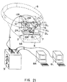
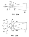
- Fig. 21 shows a schematic view illustrating the construction of the second embodiment of the glasses type display apparatus of this invention.
- the left and right lens systems 2L, 2R are provided corresponding to respective left and right display portions 1L, 1R.
- the optical axis of these lens systems 2L and 2R are reflected from the beam splitter 3 with a slant of 45 [deg] and enters left and right eyeballs (not shown) of the user.
- a liquid crystal shutter 4 is positioned in front of the beam splitter 3.
- left and right display portions 1L, 1R, left and right lens systems 2L, 2R, the beam splitter 3, and the liquid crystal shutter 4 are contained in any enclosure, such as the one 5 shown by broken lines.
- the enclosure 5 an inside wall of which is made of a material for painting in frosted black not to transmit light, adheres to the brim portion 7 of the head fitting member 6 at the face shown by a dotted chain lines. The user wears in this head fitting member 6 on his head, and can see virtual images.
- the left and right image signals applied to each left and right display portions 1L, 1R, are generated by computers 8L and 8R, and these are provided to the left and right display portions 1L, 1R via a control equipment 9. Further, the control equipment 9 generates a control signal to open or close the liquid crystal shutter 4 according to the operation of the switches.
- the left and right display portions 1L, 1R are respectively fixed to the first linear sliders 11L and 11R. These linear sliders 11L and 11R are secured to the first common slider shaft 12.
- the left and right display portions 1L and 1R are respectively fixed to the second linear sliders 13L and 13R.
- These second linear sliders 13L and 13R are respectively secured to the second and the third slider shafts 14L and 14R, and these slider shafts 14L and 14R are adhered, for example, by using an adhesive, with a predetermined angle to the enclosure 5 by fixed members 15L and 15R.
- the left and the right display portions 1L, 1R are neared to or parted from the left and the right lens systems 2L, 2R in order to adjust the visibility.
- the up or down movement of the first slider shaft 12 changes the display portions 1L and 1R in their positions on the slider shafts 14L and 14R nearing to and parting from the left and the right lens systems 2L, 2R.
- Fig. 21 depicts the optical arrangement of the left and the right display portions 1L, 1R and the left and right lens systems 2L, 2R.
- Fig. 22 fails to show the beam splitter 3.
- a central point obtained as a result of the virtual image is formed at a point B on the optical axis of the lens system 2R. It is necessary to bring the central point of the virtual image to a point C in order to make the left and the right virtual images coincide with each other. That is, the central point moves by a distance of /2 in case that the distance between the optical axis of the lens systems 2L and 2R is supposed .
- m means a transversal magnification of the virtual image
- s means a distance between a central point A of the right display portion 1R and the main point shaft of the lens system 2R
- f means a distance between the main point shaft and the focus point F.
- the second and the third slider shaft axes 14L and 14R are so positioned that the left and the right display portions 1L, 1R move along the segment line FO, it is possible to make the positions of the left and the right virtual images to be seen to coincide with each other even though visibility control changes the distance between the left and the right display portions, and the left and the right lens systems.
- the left and right display portions 1L, 1R and the left and right lens systems 2L, 2R are provided in the head fitting member 6, so that the left and right display portions 1L, 1R and lens systems 2L and 2R are fitted on a forehead of the user or above the left and the right eyes of the user.
- the beam splitter 3 slanted by about 45 [deg] relative to the optical axis of the left and the right lens systems, makes the optical axis refract, and the liquid crystal shutter 4 is placed in front of the beam splitter 3.
- the glasses type display apparatus is fitted on the user, the user can see or observe instantly the outside field when the liquid crystal shutter 4 open. It is also made possible to watch the images of the display apparatus and simultaneously seeing any work of the outside of the display apparatus.
- the head fitting member 6 has a brim portion 7 and the beam splitter 3 placed below the brim portion 7 separated from the face of the user by a predetermined distance. Thereby, it is possible to firmly have a downward eyesight, and the user can freely take off and takes on a pair of glasses without taking off the glasses type display apparatus.
- the bottom portion of the beam splitter 3 is covered with the bottom face 5A extending from the enclosure 5. Consequently, incident rays from the outside through the bottom of the beam splitter 3 can be prevented and unnecessary reflections on the left and the right display portions can be also prevented so as to improve the visibility virtual images.
- This bottom face 5A is placed to coincide with the viewing direction of the left and the right eyes of the user, so that a visibility of eyesight while seeing the outside by making the eyesight blocking range a minimum.
- FIG. 24 depicts a schematic view of construction of the third embodiment of the glasses type display apparatus of this invention.
- Fig. 24 fails to show the linear sliders 11, 13L and 13R, the slider shafts 12, 14L and 14R, and visibility adjustment mechanism of Fig. 21.
- a liquid crystal enclosure glass 16 and a polarization filter 17 are positioned at the position of the liquid crystal shutter 4 of Fig. 21.
- the left and right polarization filter 18L and 18R are positioned between the beam splitter 3 and the eyeballs by adhering to a transparent plastic board 19.
- the transparent plastic board 19 around thereof is fixed to adhere to the enclosure 5.
- a control equipment of this glasses type display apparatus a video signal of which for example, a small video tape recorder 15 (hereinafter referred to as "small VTR 15") is provided in stead of computers 8L and 8R, so as to see video images. Further, the control equipment 9 and the small VTR 15 etc., are fixed to make one body, in order to carry, by fixing to the user's belt or hanging on his shoulder.
- FIG. 25A and 25B depict respectively in Figs. 25A and 25B, as optical arrangements of which the left and the right display portions 1L, 1R, the left and right lens systems 2L, 2R, the left and the right polarization filters 18L, 18R, the liquid crystal enclosure glass 16 and the polarization filter 17, in the glasses type display apparatus.
- a displayed image is magnified by convex lenses of the left and right lens systems 2L, 2R, and then reflects it by the beam splitter 3 to lead to eyeballs 20, so that a vertical image 21 of the left and the right display portions 1L, 1R are displayed in front of the eyeballs 20.
- the liquid crystal shutter is constituted so as to provide the polarization filter 18 between the eyeballs 20 and the beam splitter 3, the liquid crystal enclosure glass 16 and the polarization filter 17 in front of the beam splitter 3.
- the size of the polarization filter 18 and its position are determined in an area of a visual field angle I (*IR, *IL) of left and right eyeballs 20R, 20L respectively as seen from the vertical image 21. Thereby, it can be hidden only the outside in the area of visual field angle of the vertical images.
- the polarization filters 18L and 18R are placed separately for the left and the right eyeballs 20L, 20R respectively, so that the outside of another eye is not hidden excessively.
- Polarization directions of the polarization filters 18L and 18R are made to coincide each other, and the direction is made to coincide with a polarization direction of the display portion 1. Thereby, even though seeing the virtual image 21 through the polarization filters 18L and 18R, there is little extinction of the virtual image 21 by the polarization filters 18L and 18R.
- Figs. 26A and 26B depict a relation between an intercept area of the outside by the liquid crystal shutter 4 of the glasses type display apparatus and a visual field angle of the vertical image.
- the outside of front visual field is almost intercepted, thus it is being prohibited in working with taking information of the outside.
- it can be hidden only the outside of the displayed area of the virtual image 21, and thus it is possible to look around so that the virtual image 21 can be seen in the other working condition.
- the visual field is not a space closed only the virtual image 21, so that even though moving his head, a disorder of the sense of equilibrium is not being generated.
- the glasses type display apparatus can be endowed with visibility control achieves in a simple manner.
- the crystal shutter consisted of the polarization filters 17, 18 and the liquid crystal enclosure glass 16 to look around.
- the virtual image 21 in other working situations can be seen, and even if the user moves his head, no disorder of the sense of equilibrium is generated.
- the area the outside is determined by the polarization filter 18 placed between eyeballs 20 and the beam splitter 3.
- the invention is not only limited to this embodiment, and the area hiding the outside field to may be set by the polarization filter 17' in front of the beam splitter 3 and the liquid crystal enclosure glass 16.
- a polarization filter 18' placed between eyeballs 20 and the beam splitter are enlarged satisfactorily, and the polarization filter 17' placed in front of the liquid crystal enclosure glass 16 is made as large as the display area of the vertical images.
- the polarization direction of the polarization filter 17' and a polarization direction after passing the liquid crystal enclosure glass 16, are set in parallel or vertical with respects to this drawing sheet.
- the polarization directions of the left and the right display portions 1L, 1R are respectively coincided with the polarization directions of the left and the right polarization filter 17' (17L', 17R'), so that the light from the left and the right display portions 1L, 1R reach the left and right eyeballs 20L and 20R.
- light passing to the left eyeball 20L for example, will pass through the polarization filter 17L' in front of the left eyeball 20L, will not reached to the left eyeball 20L, so as to hide the outside field in the visual field area of the virtual image.
- this invention is applied to the glasses type display apparatus for virtual reality.
- this invention is not only limited to this, but also is applicable widely to kinds of display apparatus, for example, a computer etc..
- the glasses type display apparatus can be realized wherein, a visibility control can be performed specifically to coincide with left and right virtual images respectively, despite changing distances between the left and the right display portions and the lens systems. Further, it is possible to change glasses while using the display, and to obtain under visual field, so as to walk with the glasses type display apparatus, and see the other display or the like while working.
- the present glasses type display apparatus does not give the user the impression of losing his sense of equilibrium, even when moving his head, and thus user's convenience can be improved.
Applications Claiming Priority (7)
| Application Number | Priority Date | Filing Date | Title |
|---|---|---|---|
| JP15826292 | 1992-06-17 | ||
| JP158262/92 | 1992-06-17 | ||
| JP15826292 | 1992-06-17 | ||
| JP162969/92 | 1992-06-22 | ||
| JP16296992 | 1992-06-22 | ||
| JP16296992 | 1992-06-22 | ||
| JP08911093A JP3298977B2 (ja) | 1992-06-22 | 1993-03-24 | 眼鏡型デイスプレイ装置 |
Publications (3)
| Publication Number | Publication Date |
|---|---|
| EP0575257A2 true EP0575257A2 (de) | 1993-12-22 |
| EP0575257A3 EP0575257A3 (de) | 1995-04-19 |
| EP0575257B1 EP0575257B1 (de) | 1999-08-18 |
Family
ID=27306033
Family Applications (1)
| Application Number | Title | Priority Date | Filing Date |
|---|---|---|---|
| EP93401562A Expired - Lifetime EP0575257B1 (de) | 1992-06-17 | 1993-06-17 | Brillenartige Anzeigeapparat |
Country Status (1)
| Country | Link |
|---|---|
| EP (1) | EP0575257B1 (de) |
Cited By (18)
| Publication number | Priority date | Publication date | Assignee | Title |
|---|---|---|---|---|
| EP0679919A2 (de) * | 1994-04-21 | 1995-11-02 | Sega Enterprises, Ltd. | Auf dem Kopf befestigte Abbildungsvorrichtung |
| EP0716329A1 (de) * | 1994-06-23 | 1996-06-12 | Seiko Epson Corporation | Auf dem kopf getragene anzeigevorrichtung |
| EP0722575A1 (de) * | 1993-10-07 | 1996-07-24 | Virtual Vision, Inc. | Auf dem kopf getragenes anzeigesystem mit aspherischer optik |
| US5598297A (en) * | 1993-08-26 | 1997-01-28 | Sharp Kabushiki Kaisha | Image display unit |
| US5712732A (en) * | 1993-03-03 | 1998-01-27 | Street; Graham Stewart Brandon | Autostereoscopic image display adjustable for observer location and distance |
| US5739893A (en) * | 1993-08-20 | 1998-04-14 | Seiko Epson Corporation | Head-mounted image display apparatus |
| EP0899599A2 (de) * | 1997-08-01 | 1999-03-03 | Colorado Microdisplay, Inc. | Am Kopf getragene Anzeigevorrichtung |
| US5936774A (en) * | 1995-08-29 | 1999-08-10 | Street; Graham S. B. | Autostereoscopic display |
| WO1999046626A1 (en) * | 1998-03-13 | 1999-09-16 | Businaro, Luca | Optical apparatus for image overlaying onto a real world scene |
| US6040945A (en) * | 1996-03-11 | 2000-03-21 | Seiko Epson Corporation | Head mount display device |
| EP1039327A2 (de) * | 1999-03-19 | 2000-09-27 | Matsushita Electric Industrial Co., Ltd. | Videoskop und seine Anzeigeeinheit |
| US6538624B1 (en) | 1993-08-20 | 2003-03-25 | Seiko Epson Corporation | Head-mounted image display apparatus |
| CN108983422A (zh) * | 2017-06-02 | 2018-12-11 | 宏达国际电子股份有限公司 | 沉浸式头戴系统及其控制方法 |
| CN110007463A (zh) * | 2018-01-04 | 2019-07-12 | 宏碁股份有限公司 | 头戴显示装置 |
| CN110579878A (zh) * | 2019-07-05 | 2019-12-17 | 华为技术有限公司 | 增强现实ar眼镜 |
| CN110915200A (zh) * | 2017-07-19 | 2020-03-24 | 日本聚逸株式会社 | 头戴式显示器 |
| US11187908B2 (en) | 2013-03-15 | 2021-11-30 | Immy Inc. | Head mounted display assembly with structural frame and separate outer frame |
| EP3913420A4 (de) * | 2019-01-15 | 2022-10-26 | Blue Optech Co., Ltd. | Am körper tragbare bildanzeigevorrichtung |
Citations (10)
| Publication number | Priority date | Publication date | Assignee | Title |
|---|---|---|---|---|
| FR2356970A1 (fr) * | 1976-06-29 | 1978-01-27 | Weissler Alain | Visionneuse optique a convergence angulaire reglable |
| GB1581926A (en) * | 1977-05-18 | 1980-12-31 | Elliott Brothers London Ltd | Visual display apparatus |
| DE8514538U1 (de) * | 1985-05-17 | 1985-07-11 | Zobel, Jürgen, 7518 Bretten | Stereoskop mit verstellbarer Augenbasis |
| US4636866A (en) * | 1982-12-24 | 1987-01-13 | Seiko Epson K.K. | Personal liquid crystal image display |
| FR2615633A1 (fr) * | 1987-05-22 | 1988-11-25 | Tak Sau Lo Anthony | Visionneuse pour paire stereoscopique de vues |
| GB2206421A (en) * | 1987-06-29 | 1989-01-05 | Marconi Gec Ltd | Binocular stereoscopic head-up display system |
| EP0344881A2 (de) * | 1988-05-31 | 1989-12-06 | Reflection Technology, Inc. | Persönliche Headup-Anzeige |
| US5034809A (en) * | 1989-04-21 | 1991-07-23 | Palca, Inc. | Personal video viewing apparatus |
| EP0438362A1 (de) * | 1990-01-19 | 1991-07-24 | Sony Corporation | Wiedergabeeinrichtung in Brillenform zur direkten Wiedergabe auf der Netzhaut |
| EP0454443A2 (de) * | 1990-04-24 | 1991-10-30 | Sony Corporation | Optisches Gerät für ein stereoskopisches Betrachtungssystem |
-
1993
- 1993-06-17 EP EP93401562A patent/EP0575257B1/de not_active Expired - Lifetime
Patent Citations (10)
| Publication number | Priority date | Publication date | Assignee | Title |
|---|---|---|---|---|
| FR2356970A1 (fr) * | 1976-06-29 | 1978-01-27 | Weissler Alain | Visionneuse optique a convergence angulaire reglable |
| GB1581926A (en) * | 1977-05-18 | 1980-12-31 | Elliott Brothers London Ltd | Visual display apparatus |
| US4636866A (en) * | 1982-12-24 | 1987-01-13 | Seiko Epson K.K. | Personal liquid crystal image display |
| DE8514538U1 (de) * | 1985-05-17 | 1985-07-11 | Zobel, Jürgen, 7518 Bretten | Stereoskop mit verstellbarer Augenbasis |
| FR2615633A1 (fr) * | 1987-05-22 | 1988-11-25 | Tak Sau Lo Anthony | Visionneuse pour paire stereoscopique de vues |
| GB2206421A (en) * | 1987-06-29 | 1989-01-05 | Marconi Gec Ltd | Binocular stereoscopic head-up display system |
| EP0344881A2 (de) * | 1988-05-31 | 1989-12-06 | Reflection Technology, Inc. | Persönliche Headup-Anzeige |
| US5034809A (en) * | 1989-04-21 | 1991-07-23 | Palca, Inc. | Personal video viewing apparatus |
| EP0438362A1 (de) * | 1990-01-19 | 1991-07-24 | Sony Corporation | Wiedergabeeinrichtung in Brillenform zur direkten Wiedergabe auf der Netzhaut |
| EP0454443A2 (de) * | 1990-04-24 | 1991-10-30 | Sony Corporation | Optisches Gerät für ein stereoskopisches Betrachtungssystem |
Non-Patent Citations (1)
| Title |
|---|
| IEEE SPECTRUM, vol.6, no.9, September 1969 pages 37 - 43 ERIC G. RAWSON 'Vibrating varifocal mirrors for 3-D imaging' * |
Cited By (34)
| Publication number | Priority date | Publication date | Assignee | Title |
|---|---|---|---|---|
| US5712732A (en) * | 1993-03-03 | 1998-01-27 | Street; Graham Stewart Brandon | Autostereoscopic image display adjustable for observer location and distance |
| US6538624B1 (en) | 1993-08-20 | 2003-03-25 | Seiko Epson Corporation | Head-mounted image display apparatus |
| US5739893A (en) * | 1993-08-20 | 1998-04-14 | Seiko Epson Corporation | Head-mounted image display apparatus |
| US5598297A (en) * | 1993-08-26 | 1997-01-28 | Sharp Kabushiki Kaisha | Image display unit |
| EP0722575A1 (de) * | 1993-10-07 | 1996-07-24 | Virtual Vision, Inc. | Auf dem kopf getragenes anzeigesystem mit aspherischer optik |
| EP0722575A4 (de) * | 1993-10-07 | 1997-01-02 | Virtual Vision Inc | Auf dem kopf getragenes anzeigesystem mit aspherischer optik |
| EP0908754A2 (de) * | 1994-04-21 | 1999-04-14 | Sega Enterprises, Ltd. | Am Kopf montierte Bildanzeigevorrichtung |
| US5774096A (en) * | 1994-04-21 | 1998-06-30 | Kabushiki Kaisha Sega Enterprises | Head mounted display |
| EP0679919A3 (de) * | 1994-04-21 | 1996-04-10 | Sega Enterprises Kk | Auf dem Kopf befestigte Abbildungsvorrichtung. |
| US6239771B1 (en) | 1994-04-21 | 2001-05-29 | Kabushiki Kaisha Sega Enterprises | Head mounted display |
| EP0679919A2 (de) * | 1994-04-21 | 1995-11-02 | Sega Enterprises, Ltd. | Auf dem Kopf befestigte Abbildungsvorrichtung |
| US6124837A (en) * | 1994-04-21 | 2000-09-26 | Kabushiki Kaisha Sega Enterprises | Head mounted display |
| EP0908754A3 (de) * | 1994-04-21 | 2000-04-12 | Sega Enterprises, Ltd. | Am Kopf montierte Bildanzeigevorrichtung |
| EP0716329A4 (de) * | 1994-06-23 | 1996-12-04 | Seiko Epson Corp | Auf dem kopf getragene anzeigevorrichtung |
| EP0716329A1 (de) * | 1994-06-23 | 1996-06-12 | Seiko Epson Corporation | Auf dem kopf getragene anzeigevorrichtung |
| US5936774A (en) * | 1995-08-29 | 1999-08-10 | Street; Graham S. B. | Autostereoscopic display |
| US6040945A (en) * | 1996-03-11 | 2000-03-21 | Seiko Epson Corporation | Head mount display device |
| US6034653A (en) * | 1997-08-01 | 2000-03-07 | Colorado Microdisplay, Inc. | Head-set display device |
| EP0899599A3 (de) * | 1997-08-01 | 1999-04-14 | Colorado Microdisplay, Inc. | Am Kopf getragene Anzeigevorrichtung |
| EP0899599A2 (de) * | 1997-08-01 | 1999-03-03 | Colorado Microdisplay, Inc. | Am Kopf getragene Anzeigevorrichtung |
| WO1999046626A1 (en) * | 1998-03-13 | 1999-09-16 | Businaro, Luca | Optical apparatus for image overlaying onto a real world scene |
| EP1039327A2 (de) * | 1999-03-19 | 2000-09-27 | Matsushita Electric Industrial Co., Ltd. | Videoskop und seine Anzeigeeinheit |
| EP1039327A3 (de) * | 1999-03-19 | 2002-05-29 | Matsushita Electric Industrial Co., Ltd. | Videoskop und seine Anzeigeeinheit |
| US6674462B1 (en) | 1999-03-19 | 2004-01-06 | Matsushita Electric Industrial Co., Ltd. | Videoscope and its display unit |
| US11187908B2 (en) | 2013-03-15 | 2021-11-30 | Immy Inc. | Head mounted display assembly with structural frame and separate outer frame |
| US10996749B2 (en) | 2017-06-02 | 2021-05-04 | Htc Corporation | Immersive headset system and control method thereof |
| CN108983422A (zh) * | 2017-06-02 | 2018-12-11 | 宏达国际电子股份有限公司 | 沉浸式头戴系统及其控制方法 |
| CN110915200A (zh) * | 2017-07-19 | 2020-03-24 | 日本聚逸株式会社 | 头戴式显示器 |
| CN110007463B (zh) * | 2018-01-04 | 2021-04-06 | 宏碁股份有限公司 | 头戴显示装置 |
| CN110007463A (zh) * | 2018-01-04 | 2019-07-12 | 宏碁股份有限公司 | 头戴显示装置 |
| EP3913420A4 (de) * | 2019-01-15 | 2022-10-26 | Blue Optech Co., Ltd. | Am körper tragbare bildanzeigevorrichtung |
| US11675196B2 (en) | 2019-01-15 | 2023-06-13 | Blue Optech Co., Ltd. | Wearable device with image display module |
| CN110579878A (zh) * | 2019-07-05 | 2019-12-17 | 华为技术有限公司 | 增强现实ar眼镜 |
| CN110579878B (zh) * | 2019-07-05 | 2021-09-14 | 华为技术有限公司 | 增强现实ar眼镜 |
Also Published As
| Publication number | Publication date |
|---|---|
| EP0575257B1 (de) | 1999-08-18 |
| EP0575257A3 (de) | 1995-04-19 |
Similar Documents
| Publication | Publication Date | Title |
|---|---|---|
| US5486841A (en) | Glasses type display apparatus | |
| EP0575257B1 (de) | Brillenartige Anzeigeapparat | |
| EP0438362B1 (de) | Wiedergabeeinrichtung in Brillenform zur direkten Wiedergabe auf der Netzhaut | |
| CA2173248C (en) | Head mounted display system with aspheric optics | |
| US4744633A (en) | Stereoscopic viewing system and glasses | |
| JP4155343B2 (ja) | 二つの光景からの光を観察者の眼へ代替的に、あるいは同時に導くための光学系 | |
| US5861936A (en) | Regulating focus in accordance with relationship of features of a person's eyes | |
| EP0592578B1 (de) | Anzeigegeraet fuer virtuelle bilder | |
| US5153569A (en) | Visual image display apparatus having a video display for one eye and a controllable shutter for the other eye | |
| US5696521A (en) | Video headset | |
| JP3298977B2 (ja) | 眼鏡型デイスプレイ装置 | |
| WO1996005532A1 (en) | Head mounted display optics | |
| US5124840A (en) | Portable viewing apparatus | |
| US4874235A (en) | Stereoscopic viewing system and method | |
| JPH09322197A (ja) | 立体視ディスプレイ装置 | |
| JP3163701B2 (ja) | 眼鏡型映像表示装置 | |
| US11543678B2 (en) | Optics mount for over-the-glasses eyewear | |
| JP3365564B2 (ja) | 眼鏡型デイスプレイ装置 | |
| JP2982214B2 (ja) | 眼鏡型映像表示装置 | |
| JP3298233B2 (ja) | 眼鏡型ディスプレイ装置 | |
| JP5838880B2 (ja) | ヘッドマウントディスプレイ | |
| JPH09266554A (ja) | 表示装置 | |
| CN218446245U (zh) | 一种视功能训练装置 | |
| JPH07191277A (ja) | 双眼式頭部装着型映像表示装置 | |
| JP2001209004A (ja) | 画像鑑賞メガネ |
Legal Events
| Date | Code | Title | Description |
|---|---|---|---|
| PUAI | Public reference made under article 153(3) epc to a published international application that has entered the european phase |
Free format text: ORIGINAL CODE: 0009012 |
|
| AK | Designated contracting states |
Kind code of ref document: A2 Designated state(s): DE FR GB |
|
| PUAL | Search report despatched |
Free format text: ORIGINAL CODE: 0009013 |
|
| AK | Designated contracting states |
Kind code of ref document: A3 Designated state(s): DE FR GB |
|
| 17P | Request for examination filed |
Effective date: 19950919 |
|
| 17Q | First examination report despatched |
Effective date: 19970722 |
|
| GRAG | Despatch of communication of intention to grant |
Free format text: ORIGINAL CODE: EPIDOS AGRA |
|
| GRAG | Despatch of communication of intention to grant |
Free format text: ORIGINAL CODE: EPIDOS AGRA |
|
| GRAG | Despatch of communication of intention to grant |
Free format text: ORIGINAL CODE: EPIDOS AGRA |
|
| GRAH | Despatch of communication of intention to grant a patent |
Free format text: ORIGINAL CODE: EPIDOS IGRA |
|
| GRAH | Despatch of communication of intention to grant a patent |
Free format text: ORIGINAL CODE: EPIDOS IGRA |
|
| GRAA | (expected) grant |
Free format text: ORIGINAL CODE: 0009210 |
|
| AK | Designated contracting states |
Kind code of ref document: B1 Designated state(s): DE FR GB |
|
| REF | Corresponds to: |
Ref document number: 69326038 Country of ref document: DE Date of ref document: 19990923 |
|
| ET | Fr: translation filed | ||
| PLBE | No opposition filed within time limit |
Free format text: ORIGINAL CODE: 0009261 |
|
| STAA | Information on the status of an ep patent application or granted ep patent |
Free format text: STATUS: NO OPPOSITION FILED WITHIN TIME LIMIT |
|
| 26N | No opposition filed | ||
| PGFP | Annual fee paid to national office [announced via postgrant information from national office to epo] |
Ref country code: FR Payment date: 20010611 Year of fee payment: 9 Ref country code: DE Payment date: 20010611 Year of fee payment: 9 |
|
| PGFP | Annual fee paid to national office [announced via postgrant information from national office to epo] |
Ref country code: GB Payment date: 20010613 Year of fee payment: 9 |
|
| REG | Reference to a national code |
Ref country code: GB Ref legal event code: IF02 |
|
| PG25 | Lapsed in a contracting state [announced via postgrant information from national office to epo] |
Ref country code: GB Free format text: LAPSE BECAUSE OF NON-PAYMENT OF DUE FEES Effective date: 20020617 |
|
| PG25 | Lapsed in a contracting state [announced via postgrant information from national office to epo] |
Ref country code: DE Free format text: LAPSE BECAUSE OF NON-PAYMENT OF DUE FEES Effective date: 20030101 |
|
| GBPC | Gb: european patent ceased through non-payment of renewal fee |
Effective date: 20020617 |
|
| PG25 | Lapsed in a contracting state [announced via postgrant information from national office to epo] |
Ref country code: FR Free format text: LAPSE BECAUSE OF NON-PAYMENT OF DUE FEES Effective date: 20030228 |
|
| REG | Reference to a national code |
Ref country code: FR Ref legal event code: ST |