EP0575176B1 - Milieu d'enregistrement optique, méthode d'enregistrement d'information et méthode de reproduction d'information - Google Patents
Milieu d'enregistrement optique, méthode d'enregistrement d'information et méthode de reproduction d'information Download PDFInfo
- Publication number
- EP0575176B1 EP0575176B1 EP93304742A EP93304742A EP0575176B1 EP 0575176 B1 EP0575176 B1 EP 0575176B1 EP 93304742 A EP93304742 A EP 93304742A EP 93304742 A EP93304742 A EP 93304742A EP 0575176 B1 EP0575176 B1 EP 0575176B1
- Authority
- EP
- European Patent Office
- Prior art keywords
- light
- layer
- absorbing layer
- reflectance
- recording
- Prior art date
- Legal status (The legal status is an assumption and is not a legal conclusion. Google has not performed a legal analysis and makes no representation as to the accuracy of the status listed.)
- Expired - Lifetime
Links
Images


Classifications
-
- G—PHYSICS
- G11—INFORMATION STORAGE
- G11B—INFORMATION STORAGE BASED ON RELATIVE MOVEMENT BETWEEN RECORD CARRIER AND TRANSDUCER
- G11B7/00—Recording or reproducing by optical means, e.g. recording using a thermal beam of optical radiation by modifying optical properties or the physical structure, reproducing using an optical beam at lower power by sensing optical properties; Record carriers therefor
- G11B7/24—Record carriers characterised by shape, structure or physical properties, or by the selection of the material
- G11B7/2407—Tracks or pits; Shape, structure or physical properties thereof
- G11B7/24085—Pits
-
- G—PHYSICS
- G11—INFORMATION STORAGE
- G11B—INFORMATION STORAGE BASED ON RELATIVE MOVEMENT BETWEEN RECORD CARRIER AND TRANSDUCER
- G11B7/00—Recording or reproducing by optical means, e.g. recording using a thermal beam of optical radiation by modifying optical properties or the physical structure, reproducing using an optical beam at lower power by sensing optical properties; Record carriers therefor
- G11B7/004—Recording, reproducing or erasing methods; Read, write or erase circuits therefor
- G11B7/0045—Recording
- G11B7/00452—Recording involving bubble or bump forming
-
- G—PHYSICS
- G11—INFORMATION STORAGE
- G11B—INFORMATION STORAGE BASED ON RELATIVE MOVEMENT BETWEEN RECORD CARRIER AND TRANSDUCER
- G11B7/00—Recording or reproducing by optical means, e.g. recording using a thermal beam of optical radiation by modifying optical properties or the physical structure, reproducing using an optical beam at lower power by sensing optical properties; Record carriers therefor
- G11B7/004—Recording, reproducing or erasing methods; Read, write or erase circuits therefor
- G11B7/005—Reproducing
- G11B7/0051—Reproducing involving phase depth effects
-
- G—PHYSICS
- G11—INFORMATION STORAGE
- G11B—INFORMATION STORAGE BASED ON RELATIVE MOVEMENT BETWEEN RECORD CARRIER AND TRANSDUCER
- G11B7/00—Recording or reproducing by optical means, e.g. recording using a thermal beam of optical radiation by modifying optical properties or the physical structure, reproducing using an optical beam at lower power by sensing optical properties; Record carriers therefor
- G11B7/24—Record carriers characterised by shape, structure or physical properties, or by the selection of the material
-
- Y—GENERAL TAGGING OF NEW TECHNOLOGICAL DEVELOPMENTS; GENERAL TAGGING OF CROSS-SECTIONAL TECHNOLOGIES SPANNING OVER SEVERAL SECTIONS OF THE IPC; TECHNICAL SUBJECTS COVERED BY FORMER USPC CROSS-REFERENCE ART COLLECTIONS [XRACs] AND DIGESTS
- Y10—TECHNICAL SUBJECTS COVERED BY FORMER USPC
- Y10S—TECHNICAL SUBJECTS COVERED BY FORMER USPC CROSS-REFERENCE ART COLLECTIONS [XRACs] AND DIGESTS
- Y10S430/00—Radiation imagery chemistry: process, composition, or product thereof
- Y10S430/146—Laser beam
Definitions
- the present invention relates to an optical recording medium (inclusive of a record blank and the resultant record) for optical information recording and reproduction, and methods for optical information recording and reproduction using the optical recording medium.
- Optical recording media have called attention as media for information recording and reproduction in recent years because of, e.g., capability of non-contact recording and reproduction and quick accessibility.
- Optical recording media proposed heretofore may for example include the following types:
- an optical recording medium of the above type (a) includes a recording layer of a film comprising principally a low-melting point metal, such as Te, in which recording layer a pit is formed by producing a hole by light illumination or by causing a change in reflectance through a crystal-amorphous phase transition.
- a low-melting point metal such as Te
- an organic light-absorption layer is irradiated with laser light to form pits therein due to decoloration and/or deformation, thus effecting recording.
- information reproduction is effected by scanning record parts (pits) formed on a track with reproducing light and detecting the pits due to a decrease in reflected light quantity from the optical recording medium at the pits.
- the decrease in reflected light quantity is however also caused by a scar formed on a dust attached to the surface of the optical recording medium, so that such scar or dust can provide a serious obstacle to accurate information reproduction.
- WO-A-89/11147 describes an optical recording medium wherein an optical recording layer is deposited over a reflective support.
- the recording layer has an original thickness corresponding to the half-wave thickness of the reading beam, and is deformed by the recording beam so as to have either a quarter-wave thickness or to be completely removed, exposing the reflective layer. Since unrecorded areas of the layer have a reflectance greater than the quarter-wave thickness regions but less than that of the reflective layer, three recording states are provided corresponding to the three reflectance levels.
- optical recording medium providing an increased reflectance at record pits
- a phase transition material is used to constitute a recording layer of which a part irradiated with a laser beam causes phase transition to form a record pit having an increased reflectance.
- This type of recording medium requires strict control of heat generated by the recording beam and is thus accompanied with a difficulty in uniform recording.
- an object of the present invention is to provide an optical recording medium which allows easy and uniform recording at a high recording sensitivity and also accurate reproduction even when it is scarred or dust is attached thereto.
- Another object of the present invention is to provide an information recording method and an information reproducing method using such an optical recording medium capable of reading and reproducing recorded information from the recording medium even when scar or dust is left on the surface of the recording medium.
- an optical recording medium comprising in sequence a transparent substrate, a light-reflecting layer, a transparent intermediate layer and a light-absorbing layer, the light-reflecting layer and the light-absorbing layer comprising an organic coloring matter;
- an optical recording medium storing information as a record pit, comprising in sequence a transparent substrate, a light-reflecting layer, a transparent intermediate layer and a light-absorbing layer, the light-reflecting layer and the light-absorbing layer, comprising an organic coloring matter;
- an information recording method comprising:
- an information reproducing method comprising:
- Figure 1 is a schematic sectional view of an embodiment of the optical recording medium (record blank) according to the present invention.
- Figure 2 is a schematic sectional view of an optical recording medium (information record) obtained by recording information in the record blank shown in Figure 1.
- Figure 3(a) is an enlarged sectional view in the neighborhood of a pit of an embodiment of the information record according to the present invention
- Figure 3(b) is a waveform diagram showing a reproduced signal (transmittance change) obtained by scanning the pit of the information record shown in Figure 3(a) with a reproducing beam.
- Figure 4(a) is an enlarged sectional view in the neighborhood of a pit of another embodiment of the information record according to the present invention
- Figure 4(b) is a waveform diagram showing a reproduced signal obtained by scanning the pit of the information record shown in Figure 4(a) with a reproducing beam.
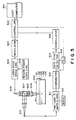
- Figure 5 is a block diagram illustrating an information recording and reproducing apparatus using an optical recording medium according to the present invention.
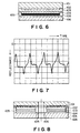
- Figure 6 is a schematic sectional view of an optical card according to Example 1 of the invention.
- Figure 7 is a reproduced signal waveform diagram of the optical card of Example 1.
- Figure 8 is a schematic sectional view of an optical disk according to Example 2 of the invention.
- Figure 9 is a graph showing a relationship between the reflectance R (%) and the thickness of transparent intermediate layer of the optical card of Example 1.
- Figure 10 is a block diagram for illustrating a comparator shown in Figure 5.
- Figure 11(a) is a waveform diagram showing a reproduced signal at a pit of an information record
- Figure 11(b) shows a differential waveform corresponding to the reproduced signal shown in Figure 11(a)
- Figure 11c shows a digital signal obtained by treating the reproduced signal shown in Figure 11(a) by a comparator illustrated in Figure 10.
- Figure 12 is a graph showing a relationship between the reflectance R (%) and the thickness of transparent intermediate layer of the optical disk of Example 2.
- Figure 1 is a schematic sectional view of an optical recording medium (record blank) before information recording according to the present invention.
- the optical recording medium includes a transparent substrate 101, a light-reflecting layer 102, a transparent intermediate layer 103, a light-absorbing layer 104, an adhesive layer 105 and a protective substrate 106.
- the light-reflecting layer 102 and light-absorbing layer 104 may respectively be composed as an organic coloring matter layer, i.e., a layer comprising an organic coloring matter.
- Figure 2 is a schematic sectional view showing a manner of pit formation, wherein the record blank shown in Figure 1 is moved in the direction of an arrow A and simultaneously a recording beam 201 having a prescribed intensity is incident through the transparent substrate 101 to the light-absorbing layer 104, thereby forming a record pit 202 accompanied with a geometrical deformation.
- the sectional view of Figure 2 is taken along the scanning direction A.
- the optical constants of the above-mentioned light-reflecting layer 102, transparent intermediate layer 103 and light-absorbing layer 104 and the thicknesses of these layers other than the transparent intermediate layer 103 are set so as to constitute a multi-layer optical element with respect to a reproducing light beam having a wavelength ⁇ r incident to the light-absorbing layer 104 through the transparent substrate 101, which multi-layer optical element shows a minimum reflectance and a maximum reflectance of the reproducing beam at the incident surface of the optical recording medium at different thicknesses of the transparent intermediate layer due to optical interference effects of the respective layers, e.g., as shown in Figure 9, and the thickness of the transparent intermediate layer 103 is so set as to provide a mediate reflectance between the maximum and minimum reflectances.
- a mediate reflectance between the minimum and maximum reflectances may preferably mean a reflectance falling within a range covering central five tenths (5/10), more preferably central three tenths (3/10) of the range between the minimum and maximum reflectances.
- the medium reflectance may preferably fall within a range of 15 - 45 % (30 % ⁇ 60 % x 0.5/2), more preferably within a range of 21 - 39 % (30 % ⁇ 60 x 0.3/2).
- a record pit 202 accompanied with a geometrical shape change is formed in the light-absorbing layer as shown in Figure 2, and the transparent intermediate layer 103 is provided with varying thicknesses, i.e., a smaller thickness and then a larger thickness in the scanning direction of the recording beam, within the part of the record pit 202, respectively, compared with the prescribed thickness of the transparent intermediate layer outside the record pit 202, i.e., at non-record parts.
- Such a thickness change of the transparent intermediate layer in the optical recording medium of the present invention changes the interference effect with respect to the reproducing beam of a laminate including the transparent substrate, light-reflecting layer, transparent intermediate layer and light-absorbing layer to provide a new multi-layer optical element.
- the reflectance of the reproducing beam (i.e., reproduced signal) at the pit is such that it causes a successive change of first a higher and then a lower reflectance (as shown in Figure 3(b)) or a successive change of first a lower and then a higher reflectance (as shown in Figure 4(b)), respectively compared with a reference reflectance of the reproducing beam at the non-record parts, according to the new multi-layer optical element.
- the thickness of the transparent intermediate layer 3 has been generally described above, but the thickness may preferably be set so as to satisfy the above condition within the range of at least 1000 ⁇ , more preferably at least 1500 ⁇ , further preferably at least 3000 ⁇ and at most 2 ⁇ m. More specifically, if the thickness of the transparent intermediate layer 3 is made 1000 ⁇ or larger, it is possible to prevent the breakage of the multi-layer optical element composed by the transparent substrate, light-reflecting layer, transparent intermediate layer and light-absorbing layer providing a successive change in reflectance due to the diffusion of heat generated in the light-absorbing layer by irradiation with the recording beam into the light-reflecting layer thus causing deformation or decoloration of the light-reflecting layer.
- the light-reflecting layer in the optical recording medium according to the present invention may preferably have a thickness d ref which is set to provide a pit showing a larger increase in reflectance of the reproducing beam compared with the reference value thereof so as to prevent a reproduction error due to attachment of dust or scar.
- d ref thickness of the reproducing beam
- the attachment of dust or scar lowers the reflectance of the reproducing beam by the optical recording medium, so that the increase in reflectance of the reproducing beam at a pit provides an important factor in the information reproducing method of the present invention for differentiating a change in reflectance of the reproducing beam due to the dust or scar and a change in reflectance of the reproducing beam due to a pit.
- d abs may preferably satisfy a relationship of: ( l n2 ⁇ w/2 ⁇ k abs ) ⁇ d abs ⁇ ⁇ w/3n abs ), wherein ⁇ w denotes the wavelength of the recording beam.
- the wavelength ⁇ r of the reproducing beam may preferably be set to be substantially identical to the reflection maximum wavelength ⁇ (R ref max) of the light-reflecting layer and to satisfy a relationship of the following formula (4) with the absorption maximum wavelength ⁇ ref max of the light-reflecting layer so as to further increase the reflectance of the reproducing beam at the light-incidence surface of the optical recording medium according to the present invention: ⁇ r - ⁇ ref max > 100 nm
- the light-reflecting layer 102 and the light-absorbing layer 104 may preferably be formed to provide mutually different maximum absorption wavelengths. It is particularly preferred that the organic coloring matters constituting the light-reflecting layer 102 and the light-absorbing layer 104 and/or the wavelength ⁇ w of the recording beam are set to be substantially identical to the maximum absorption wavelength ⁇ abs max and to satisfy a relationship of the following formula (3) with the maximum absorption wavelength ⁇ ref max of the light-reflecting layer: ⁇ w > ⁇ ref max
- the maximum absorption wavelength of the light-reflecting layer is shorter than the wavelength of the recording beam, so that the absorption of the recording beam by the light-reflecting layer becomes small, and the reflection of the recording beam becomes high because the maximum reflection wavelength is generally longer than the maximum absorption wavelength.
- the absorption peak wavelength of the light-absorbing layer 104 substantially coincide with the wavelength of the recording beam, the absorption efficiency of the recording beam is increased. As a result, it is possible to obtain an organic optical recording medium showing a high reflectance while suppressing a lowering in recording sensitivity accompanying an increased reflectance at the surface to retain a good recording sensitivity.
- the materials of the optical recording medium and/or the wavelength of the recording beam are selected so that a light beam having a wavelength identical to the wavelength ⁇ w of the recording beam shows an absorption of at most 20 %, particularly at most 10 %, at the light-reflecting layer, an absorption of at most 5 %, particularly at most 1 %, at the transparent intermediate layer, and an absorption of at least 50 %, particularly at least 60 %, at the light-absorbing layer.
- the recording beam is not remarkably attenuated due to absorption by the light-reflecting layer to effectively reach the light-absorbing layer, thus allowing recording at good sensitivity by formation of pits in the light-absorbing layer and light-reflecting layer.
- the materials of the light-reflecting layer and transparent intermediate layer and/or the wavelength of the reproducing beam it is possible to provide a further higher reflectance at the light-incidence surface of the optical recording medium due to interference by the multi-layer optical element.
- the transparent substrate 101 may suitably be transparent to laser light so as to allow recording and reproduction through the substrate.
- the substrate may comprise, e.g., plastics, such as polyester resin, acrylic resin, polyamide resin, polycarbonate resin, polyolefin resin, phenolic resin, epoxy resin and polyimide resin, and glass.
- the surface of the substrate may be provided with a preformat, such as guide grooves, guide pits or address signals for tracking, which may be formed directly in the plastics or glass constituting the substrate or in a coating layer of, e.g., a photopolymer resin.
- a preformat such as guide grooves, guide pits or address signals for tracking, which may be formed directly in the plastics or glass constituting the substrate or in a coating layer of, e.g., a photopolymer resin.
- Light-reflecting layer (102) and Light-absorbing Layer (104) are Light-reflecting layers (102) and Light-absorbing Layer (104)
- the light-reflecting layer and light-absorbing layer may respectively be constituted as a layer comprising an organic coloring matter, suitable examples of which may include dyes of polymethine-type, azulene-type, pyrylium-type, squalium-type, croconium-type, triphenylmethane-type, xanthene-type, anthraquinone-type, cyanine-type, phthalocyanine-type, dioxazine-type, tetrahydrocholine-type, triphenothiazine-type, phenanthrene-type, aminium salt-diimmonium slat-type, and metal complex-type. Pigments of similar structures can also be used.
- the light-absorbing layer may preferably be composed by a material providing a maximum absorption wavelength ⁇ abs max which is substantially equal to ⁇ w, the wavelength of the recording light beam, and the light-reflecting layer may preferably be composed by a material providing a maximum reflection wavelength ⁇ (R ref max) which is substantially equal to ⁇ r, the wavelength of the reproducing light beam.
- the above-mentioned substantial equality between ⁇ w and ⁇ abs max is satisfied when the following formula (5) is satisfied: ⁇ abs max - ⁇ w ⁇ 50 nm Further, the above-mentioned substantial equality between ⁇ r and ⁇ (R ref max) is satisfied when ⁇ r is within a wavelength region in which a single layer of the light-reflecting layer shows 0.7 to 1.1 times the maximum absorptance which the single layer of the light-reflecting layer shows with respect to light having the wavelength of ⁇ (R ref max).
- the light-absorbing layer may preferably show an absorptance of at least 50 %, particularly at least 60 %, with respect to the recording light beam
- the light-reflecting layer may preferably show an absorptance of at most 20 %, particularly at most 10 %, with respect to both the recording light beam and the reproducing light beam, whereby recording can be performed at a high sensitivity to provide a record and the record can be reproduced at a high contrast.
- An optical stabilizer such as an aminium salt or diimonium salt, can be used together with the above-mentioned organic coloring matter.
- the light-reflecting layer and the light-absorbing layer may suitably be formed as binder-free layers, but an appropriate binder can be included in the light-reflecting layer and/or the light-absorbing layer in order to improve the film-forming characteristic.
- the transparent intermediate layer 103 may be composed by a material which shows substantial transparency, more specifically an absorptance of at most 5 %, particularly at most 1 %, with respect to both laser light beams having wavelengths ⁇ w and ⁇ r and may be formed in a thickness satisfying the above-mentioned requirement, i.e., providing media transmittance between the maximum and minimum transmittances.
- the material may include: organic resins, such as polyvinyl alcohol and polyvinyl acetal resin, polyurethane resin, polyamide resin, polystyrene resin, cellulose derivatives, ethylene-vinyl acetate copolymer, ethylene-acrylic acid copolymer, polyolefin resin and copolymers thereof, polycarbonate resin, acrylic resin, silicone resin, polyester resin, polyparaxylylene, and petroleum resin.
- the transparent intermediate layer may be formed as a film of such a resin, formed, e.g., by various coating methods, vapor deposition, plasma polymerization, or CVD process.
- the optical recording medium according to the present invention may be prepared, e.g., by coating a transparent substrate 101 in sequence with an organic coloring matter layer (light-reflecting layer 102), a transparent intermediate layer 103 and an organic coloring matter layer (light-absorbing layer 104) respectively in prescribed thicknesses by various coating methods, vapor deposition, plasma polymerization, CVD process, etc., and the light-absorbing layer 104 may be further covered with a protective layer 106 by the medium of an adhesive layer 105.
- the optical recording medium may be constituted by forming a light-reflecting layer 102 on a transparent substrate 101, forming a light-absorbing layer 104 on a protective substrate 106, and bonding the light-reflecting layer 102 and the light-absorbing layer 104 with the transparent intermediate layer 103.
- the recording light beam incident to the transparent substrate 101 is first reflected at the surface of the light-reflecting layer.
- some tenths of the incident light beam are allowed to pass through the light-reflecting layer 102 and the transparent intermediate layer 103 to be focused at the light-absorbing layer 104 since the light-reflecting layer 102 in the present invention comprises an organic coloring matter.
- the focused light beam is absorbed and converted into heat at the light-absorbing layer, thereby to form a record pit accompanied with a geometrical shape change.
- the formation of a record pit in the light-absorbing layer may be accompanied with a successive change of first a smaller thickness and then a larger thickness of the transparent intermediate layer in the scanning direction of the recording beam, respectively compared with a prescribed thickness at non-recorded parts of the transparent intermediate layer.
- the successive change in thickness of the transparent intermediate layer it is possible to form a new multi-layer optical element including the transparent substrate, light-reflecting layer, transparent intermediate layer and light-absorbing layer providing a successive change in reflectance of a reproducing beam having a wavelength ⁇ r of first a lower and then a higher reflectance at the record pit than a reference reflectance at non-recorded parts when a track including the record pit is scanned with the reproducing beam.
- the recording beam intensity used in the information recording method according to the present invention can vary in various manners depending on the specific structure and material of the optical recording medium according to the present invention, but the upper limit thereof may preferably be set so as not to cause a change, such as deformation or decoloration, of the light-reflecting layer for the purpose of forming a multi-layer optical element showing a successive change in reflectance of the reproducing beam as described above at the record pit.
- Information reproduction from the optical recording medium carrying recorded information according to the present invention is performed by continuously moving the optical recording medium relative to a reproducing beam and causing the reproducing beam to be incident through the transparent substrate to detect a reflected portion of the reproducing beam from the optical recording medium, thereby reproducing the information.
- the reproducing beam is set to have a wavelength ⁇ r providing reflectance at non-recorded parts which is mediate between the minimum and maximum reflectances caused by changes in thickness of the transparent intermediate layer, the record pit is caused to provide a successive change as described above of the reproducing beam.
- the reflectance by the optical recording medium according to the present invention can be further increased.
- the information reproducing method according to the present invention it is possible to further enhance an increase in reflectance at the pit from the reference reflectance at non-recorded parts, thus providing an enhanced accuracy of pit detection.
- the recording beam wavelength ⁇ w is made substantially equal to the maximum absorption wavelength ⁇ abs max of the light-absorbing layer, it is possible to realize a high-sensitivity information recording method.
- the recording beam wavelength ⁇ w and the reproducing beam wavelength ⁇ r are equal to each other in the present invention, it is particularly preferred to set ⁇ w and ⁇ abs max to be substantially equal to each other as described above.
- the optical recording medium according to the present invention is constituted to show a high reflectance at the wavelength of the reproducing light beam as described above, and the sensitivity to the recording light beam of the optical recording medium is also substantially lowered in the case where the wavelengths of the recording light beam and the reproducing light beam are equal to each other.
- ⁇ w and ⁇ abs max it is possible to control the sensitivity of the optical.recording medium to the recording light beam to such a level that a light beam having an excessive power is not required for recording.
- an information recording and reproducing system as shown includes a record blank 500 (similar to the one shown in Figure 1) which is moved by a driving means (not shown).
- Recording data sent from a host computer 501 is subjected to parallel-to-serial data conversion, addition of error correction code, etc. by a controller 502 for controlling the apparatus for recording and reproducing data in and from the medium 500, and then the serial data is converted into code signals by a modulating circuit 503.
- the coded signal data is sent through a laser diode drive circuit 504 connected to a recording power control circuit 505 to a laser diode 506, which issues a recording light beam having varying intensities changing between a high level and a low level depending on the modulated data.
- the recording light beam passing a polarizing beam splitter 507 is converted into circular polarized light when it passes through a quarter wave plate 508.
- the circular polarized light is focused by a condenser lens 509 into a spot beam with a diameter of about 1 ⁇ m, which is then incident to the recording medium 500 from the side of the substrate 1 to be focused at the light-absorbing layer 104.
- the intensity of the recording light beam is at its high level
- the light beam-focused part of the light-absorbing layer 104 of the record blank 500 is heated to form a pit (202 in Figure 2) thereat in the light-absorbing layer 104 and also a thickness change in the transparent intermediate layer 103.
- the intensity is at its low level
- no change occurs in the light-absorbing layer or transparent intermediate layer.
- a new multi-layer optical element showing a successive change in reflectance of the reproducing light beam is formed, thus resulting in a record pit.
- the record blank 500 including the light-absorbing layer 104 is moved by the driving means (not shown) successively relative to the recording light beam, whereby an information or data track comprising a series of such record pits is formed.
- the medium 500 having a plurality of such record pits or such information tracks each including a plurality of record pits provides an information record.
- the output power level of the laser diode 507 is fixed by the control circuit 503 - 505 to a constant level below that required for forming an optically detectable change in the light-absorbing layer 104.
- the reproducing laser beam at a constant level is passed through the polarizing beam splitter 507, the quarter wave plate 508 and the condenser lens 509 to be focused onto an information track to be reproduced of the information record 500.
- the light reflected from the information record surface is again passed through the quarter wave plate 508 after which the reflected light is caused to have a polarized light plane which is different by 90 degrees from the incident light and is reflected by the beam splitter 507 to reach an optical detector 510.
- the intensity of the light entering the detector 510 is changed when the focused beam passes over the record pit 202 in the light-absorbing layer 104.
- the output from the optical detector 510 is amplified and transformed into a reproduced signal, a focus servo signal and a tracking servo signal by a pre-amplifier and matrix circuit 511.
- the focus servo signal and tracking servo signal are sent to a servo control system 512.
- the reproduced signal outputted from the matrix circuit 511 is converted into a digital signal by a comparator 513 and sent to a phase locked loop (PLL) circuit 514 at which a clock signal is extracted.
- PLL phase locked loop
- the comparator 513 is constituted as shown in more detail in Figure 10 and used to effect signal processing as will be illustrated with reference to Figure 11 to convert an analog signal based on a reflectance change from the optical recording medium into a digital signal. More specifically, an analog signal 111 ( Figure 11) is separated into two signals, one of which is introduced into a window comparator 513-1. In the window comparator 513-1, the reflectance at a non-recorded part of the optical recording medium is taken as the base level and, on both + and - sides of the base level, slice levels 112 are respectively set, whereby points of time at which the inputted analog signal exceeds the respective slice levels are memorized (Figure 11(a)).
- the other separated analog signal 111 is introduced into a differentiator 513-2 to be differentiated thereby to obtain a differential signal 113. Then, the differential signal 113 is introduced to a zero-comparator 513-3 where zero-cross points are detected ( Figure 11(b)).
- a pair of zero-cross points 114 and 115 causing two types of signal sign inversion (i.e., positive to negative at point 114 and negative to positive at point 115 in this embodiment) of the differential signal is detected as indicating the presence of a record pit, whereby an analog signal including a successive change of first a higher and then a lower reflectance with respect to a reference reflectance at non-recorded parts of the optical recording medium as shown in Figure 11(a) can be converted into a digital signal as shown in Figure 11(c).
- an analog signal including a successive change of first a lower and then a higher reflectance may be converted into a pair of zero-cross points (114 and 115) causing reverse two types of signal sign inversion (i.e., negative to positive at point 114 and positive to negative at point (115) of the differential signal, thus providing a digital signal indicating another type of record pit.
- the clock signal from the PLL circuit 514 ( Figure 5) is used for synchronizing demodulation of the reproduced signal at a data synchronizing and detection system 515. Then, the signal from the detection system 515 is demodulated by a demodulator circuit 516 according to an algorithm reverse to that for the modulation into data of the original type, which is then sent to the controller 502 to be read by the host computer 501.
- the laser diode 506, beam splitter 507, quarter wave plate 508, condenser lens 509 and optical detector 510 in combination form an optical head, which is driven to an objective track for recording and reproduction based on the data from the controller 502, and the movement of the optical head and the medium 500 is controlled by the servo control system 512 based on signals including the focus servo signal and tracking servo signal sent from the matrix circuit 511.
- the optical recording medium according to the present invention can afford effective utilization of light, particularly semiconductor laser light, for recording by independently disposing a light-reflecting layer and a light-absorbing layer respectively comprising an organic coloring matter.
- the "successive change" in transmittance used herein is not limited to a positive-to-negative or negative-to-positive transmittance change with respect to a reference reflectance is caused in succession or continuously with time but also covers a transmittance change including a positive transmittance and a negative occurring with a time spacing therebetween as far as the transmittance change is caused by scanning a single pit with a reproducing beam.
- An optical card having a cross section as shown in Figure 6 was prepared in the following manner.
- an optical card substrate 101 was prepared by coating a 0.4 mm-thick acrylic resin plate of 86 mm in longer side and 54 mm in shorter side with a layer of a photopolymer resin (trade name: "30X717", available from Three Bond K.K.) to which was transferred a pattern of stripe-shaped guide grooves of 3 ⁇ m in width, 12 ⁇ m in pitch and 2500 ⁇ in depth by the 2P-process.
- the substrate 101 was gravure-coated with an about 1000 ⁇ -thick light-reflecting layer 102 of a compound of the following structural formula [I].
- a 50 ⁇ m-thick PET polyethylene terephthalate film substrate 601 of 72 mm x 35 mm was coated with a 5.5 wt. % solution in diacetone alcohol of a compound of the following structural formula [II] to form an about 900 ⁇ -thick light-absorbing layer 104.
- the optical card substrate and the PET film were laminated with each other so that the transparent intermediate layer 103 and the light-absorbing layer 104 contacted each other, followed by lamination on the PET film of a 50 ⁇ m-thick hot melt-type adhesive sheet 105 ("7580", mfd. by Hirodine K.K.) and a 0.25 mm-thick polycarbonate protective substrate 106 and heat lamination of the entire laminate by passing through hot rollers to obtain an optical card having a structure as shown in Figure 6.
- optical cards generally having the structure described above but having varying thicknesses of transparent intermediate layer are irradiated with a light beam having a wavelength of 8300 ⁇
- a relationship between the reflectance observed at the incidence surface of the optical card and the thickness of the transparent intermediate layer as shown in Figure 9.
- the optical card having the structure adopted in this Example shows a minimum reflectance of 0 % at a transparent intermediate layer thickness of 5200 ⁇ and a maximum reflectance of 46 % at 6500 ⁇ .
- the transparent intermediate layer thickness of this Example was set to provide substantially a half value of 23 % between the maximum and maximum-transmittances.
- the optical card was set in an optical card recording/reproducing apparatus and subjected to information recording and reproduction by using recording and reproducing beams respectively incident through the transparent substrate under the following conditions:
- the record pits of the optical card thus formed after the recording were observed through a microscope, whereby deformation of the light-absorbing layer was observed but no deformation or decoloration of the light-reflecting layer was observed.
- each record pit of the optical card formed in this Example provided a successive change in reflectance including an increase and then a decrease, respectively compared with the reference reflectance level at non-record parts. Further, when such a successive reflectance change was detected as a pit, the reproduction method showed a bit error rate of 1.0x10 -6 as measured by dividing the number of mis-matched bits with the total number of recording signal bits.
- An optical card was prepared in the same manner as in Example 1 except that the transparent intermediate layer was omitted.
- the optical card was subjected to information recording/reproduction in the same manner as in Example 1, whereby the record pit merely provided a decrease in reflectance of the reproducing beam compared with the reference reflectance at non-record parts.
- the optical card When the optical card was subjected to measurement of bit error rate by a conventional reproduction method wherein a decrease in reflectance was detected as a record pit, the card provided a bit error rate of 1.2x10 -4 .
- An optical card was prepared by forming only the light-reflecting layer on the optical card substrate used in Example 1.
- the light-reflecting layer identical to the one used in Example 1 was subjected to measurement of the maximum absorption wavelength, the maximum reflection wavelength, the maximum absorptance, the maximum reflectance and the absorptance of light having a wavelength of 830 nm by using a spectro-photometer ("U-3400", mfd. by Hitachi K.K.). The results are shown in Table 1 below.
- An optical card was prepared by forming only the light-absorbing layer on the optical card substrate used in Example 1.
- the light-absorbing layer identical to the one used in Example 1 was subjected to measurement of the maximum absorption wavelength, the maximum reflection wavelength, the maximum absorptance, the maximum reflectance and the absorptance of light having a wavelength of 830 nm similarly as in Reference Example 1. The results are shown in Table 1 below.
- the solution was prepared by dissolving the compound of the formula [III] in diacetone alcohol at a concentration of 5.5 wt. % and dripped and spread over the disk substrate rotating at 3000 rpm for 60 sec.
- a protective substrate of the same size and material as the above-mentioned disk substrate was coated with a 1000 ⁇ -thick light-absorbing layer also in an annular shape having an inner radius of 20 mm and an outer radius of 63 mm formed by spin-coating of a diacetone alcohol solution of an organic coloring matter of the above-mentioned structural formula [II].
- the solution was prepared by dissolving the compound of the formula [II] in diacetone alcohol at a concentration of 5.5 wt. % and dripped and spread for 90 sec. over the protective substrate while rotating the protective substrate at 3000 rpm.
- an ultraviolet-curable adhesive 105 (trade name: "KRX-650-4", available from Asahi Denka K.K.) was applied at inner and outer peripheral parts of the disk substrate 101 and the protective substrate 106, and these substrates were applied to each other so that the transparent intermediate layer 103 and the light-absorbing layer 104 contacted each other, whereby an optical disk (record blank) having a cross-section as shown in Figure 8 was prepared.
- optical disks generally having the structure described above but having varying thicknesses of transparent intermediate layer are irradiated with a light beam having a wavelength of 8300 ⁇
- a relationship between the reflectance observed at the incidence surface of the optical card and the thickness of the transparent intermediate layer as shown in Figure 12.
- the optical card having the structure adopted in this Example shows a maximum reflectance of 40 % at a transparent intermediate layer thickness of 3500 ⁇ and a minimum reflectance of 0 % at 5000 ⁇ .
- the transparent intermediate layer thickness of this Example was set to provide substantially a half value of 20 % between the maximum and maximum-transmittances.
- the optical disk was set in an optical disk evaluating apparatus (trade name: "OMS-1000", available from Nakamichi K.K.) and subjected to information recording by irradiating the optical disk rotated at a linear speed of 5.6 m/sec with a recording light beam incident through the transparent substrate and having a wavelength of 830 nm, a beam spot diameter of 1.6 ⁇ m and power of 6.0 mW at a recording pulse width of 350 nsec.
- OMS-1000 optical disk evaluating apparatus
- the protective substrate and the transparent substrate of the optical disk were respectively peeled off and observed through an optical microscope, whereby deformation of the light-absorbing layer was observed, but no deformation or decoloration of the light-reflecting layer was observed.
- an optical disk prepared and subjected to recording in quite the same manner as above was subjected to information reproduction in the above-mentioned optical disk evaluating apparatus by using a reproducing beam incident through the transparent substrate and having a wavelength of 830 nm, a beam spot diameter of 1.0 ⁇ m and a power of 0.2 mW, whereby each record pit showed a successive change in transmittance including first a decrease and then an increase, respectively compared with the reference reflectance at non-record parts, i.e., reverse to that shown in Figure 7.
- the optical disk after the recording in the above-described manner showed a bit error rate of 1.1x10 -6 .
- An optical disk was prepared in the same manner as in Example 2 except that the transparent intermediate layer was omitted.
- the optical disk was subjected to information recording/reproduction in the same manner as in Example 2, whereby the record pit merely provided a decrease in reflectance of the reproducing beam compared with the reference reflectance at non-record parts.
- the disk When the optical disk was subjected to measurement of bit error rate by a conventional reproduction method wherein a decrease in reflectance was detected as a record pit, the disk provided a bit error rate of 1.0x10 -4 .
- An optical disk was prepared by forming only the light-reflecting layer on the optical disk substrate used in Example 2.
- the light-reflecting layer identical to the one used in Example 2 was subjected to measurement of the maximum absorption wavelength, the maximum reflection wavelength, the maximum absorptance, the maximum reflectance and the absorptance of light having a wavelength of 830 nm by using a spectro-photometer ("U-3400", mfd. by Hitachi K.K.). The results are shown in Table 2 below.
- An optical disk was prepared by forming only the light-absorbing layer on the optical disk substrate used in Example 2.
- the light-absorbing layer identical to the one used in Example 2 was subjected to measurement of the maximum absorption wavelength, the maximum reflection wavelength, the maximum absorptance, the maximum reflectance and the absorptance of light having a wavelength of 830 nm similarly as in Reference Example 1. The results are shown in Table 2 below.
Landscapes
- Optical Record Carriers And Manufacture Thereof (AREA)
- Optical Recording Or Reproduction (AREA)
Claims (14)
- Support d'enregistrement optique (500), comprenant successivement un substrat transparent (101), une couche réfléchissant la lumière (102), une couche intermédiaire transparente (103) et une couche absorbant la lumière (104), la couche réfléchissant la lumière (102) et la couche absorbant la lumière (104) comprenant une matière colorante organique ;la couche absorbant la lumière (104) étant capable de subir une déformation pour enregistrer une information accompagnée d'un changement local d'épaisseur de la couche intermédiaire transparente en réponse à un faisceau d'enregistrement (201) incident sur la couche absorbant la lumière (104) à travers le substrat transparent (101),le substrat transparent (101), la couche réfléchissant la lumière (102), la couche intermédiaire transparente (103) et la couche absorbant la lumière (104) constituant ensemble un élément optique multicouche vis-à-vis d'un faisceau de reproduction ayant une longueur d'onde prescrite et incident sur la couche absorbant la lumière à travers le substrat transparent, dans lequel :l'élément optique multicouche (101, 102, 103, 104) est formé de façon à produire une cuvette (202) accompagnée du changement d'épaisseur de la couche intermédiaire transparente (103), la cuvette (202) présentant un changement successif de réflectance entre des réflectances maximale et minimale d'un faisceau de reproduction (301, 401) incident sur la couche absorbant la lumière (104) à travers le substrat transparent (101) lors du balayage de la cuvette par le faisceau de reproduction (301, 401), etla couche intermédiaire transparente (103) est formée avec une épaisseur produisant une réflectance intermédiaire entre les réflectances maximale et minimale.
- Support d'enregistrement optique (500), stockant une information sous la forme d'une cuvette d'enregistrement (202) comprenant successivement un substrat transparent (101), une couche réfléchissant la lumière (102), une couche intermédiaire transparente (103) et une couche absorbant la lumière (104), la couche réfléchissant la lumière (102) et la couche absorbant la lumière (104) comprenant une matière colorante organique ;la couche absorbant la lumière (104) étant pourvue d'une cuvette d'enregistrement (202) accompagnée d'une déformation géométrique et d'une variation d'épaisseur de la couche intermédiaire transparente (103) pour l'enregistrement d'informations formées par un faisceau d'enregistrement (201) incident sur la couche absorbant la lumière (104) à travers le substrat transparent (101) ;le substrat transparent (101), la couche réfléchissant la lumière (102), la couche intermédiaire transparente (103) et la couche absorbant la lumière (104) constituant ensemble un élément optique multicouche vis-à-vis d'un faisceau de reproduction (201) ayant une longueur d'onde prescrite et incident sur la couche absorbant la lumière (104) à travers le substrat transparent (101), dans lequel :l'élément optique multicouche (101, 102, 103, 104) produit, lorsqu'une cuvette d'enregistrement est balayée par le faisceau de reproduction, une variation successive de réflectance tout d'abord plus élevée puis plus faible, ou une variation successive de réflectance tout d'abord plus faible puis plus élevée, par comparaison à une réflectance de référence dans des parties non enregistrées.
- Support d'enregistrement selon la revendication 1 ou 2, dans lequel la couche réfléchissant la lumière (102) a une épaisseur dref satisfaisant à une relation donnée par la formule (1) ci-dessous :
- Support d'enregistrement selon la revendication 3, dans lequel l'épaisseur dref satisfait à une relation donnée par la formule (2) ci-dessous :
- Support d'enregistrement selon la revendication 1 ou 2, dans lequel la couche réfléchissant la lumière (102) présente une longueur d'onde de réflexion maximale λ(Rrefmax) qui est sensiblement égale à la longueur d'onde λr du faisceau de reproduction (301, 401).
- Support d'enregistrement selon la revendication 1 ou 2, dans lequel la couche absorbant la lumière (102) présente une longueur d'onde d'absorption maximale λabsmax qui est sensiblement égale à la longueur d'onde λw du faisceau d'enregistrement (201), et la couche réfléchissant la lumière (102) présente une longueur d'onde d'absorption maximale λRrefmax satisfaisant à une relation donnée par la formule (3) ci-dessous :
- Support d'enregistrement selon la revendication 5, dans lequel la couche réfléchissant la lumière (102) présente une longueur d'onde d'absorption maximale λrefmax satisfaisant à une relation donnée par la formule (4) ci-dessous avec la longueur d'onde λr du faisceau de reproduction (301, 401) :
- Support d'enregistrement selon la revendication 7, dans lequel λabsmax et λw satisfont à une relation donnée par la formule (6) ci-dessous :
- Support d'enregistrement selon la revendication 1 ou 2, dans lequel la couche réfléchissant la lumière (102) présente une absorptance d'au moins 20 % et la couche intermédiaire transparente (103) présente une absorptance d'au plus 5 %, respectivement, du faisceau de reproduction (301, 401).
- Support d'enregistrement selon la revendication 1 ou 2, dans lequel la couche réfléchissant la lumière (102) présente une absorptance d'au plus 20 %, la couche intermédiaire transparente (103) présente une absorptance d'au plus 5 %, et la couche absorbant la lumière (104) présente une absorptance d'au moins 50 %, respectivement, du faisceau d'enregistrement.
- Support d'enregistrement selon la revendication 2, dans lequel la couche intermédiaire transparente (103) forme à l'emplacement de la cuvette d'enregistrement (202) une variation successive respectivement tout d'abord d'une première épaisseur réduite puis d'une épaisseur accrue, par rapport à une épaisseur de référence dans une partie non enregistrée de celui-ci, dans une direction de balayage par le faisceau d'enregistrement (301, 401).
- Procédé d'enregistrement d'informations, comprenant :l'utilisation d'un support d'enregistrement optique (500) comprenant successivement un substrat transparent (101), une couche réfléchissant la lumière (102), une couche intermédiaire transparente (103) et une couche absorbant la lumière (104), la couche réfléchissant la lumière (102) et la couche absorbant la lumière (104) comprenant une matière colorante organique ;la couche absorbant la lumière (104) étant capable de subir une déformation pour enregistrer une information accompagnée d'un changement local d'épaisseur de la couche intermédiaire transparente (103) en réponse à un faisceau d'enregistrement (202) incident sur la couche absorbant la lumière (104) à travers le substrat transparent (101) ;le substrat transparent (101), la couche réfléchissant la lumière (102), la couche intermédiaire transparente (103) et la couche absorbant la lumière (104) constituant ensemble un élément optique multicouche vis-à-vis d'un faisceau de reproduction (301, 401) ayant une longueur d'onde prescrite et incident sur la couche absorbant la lumière (104) à travers le substrat transparent (101), l'élément optique multicouche (101, 102, 103, 104) étant formé de façon à produire une cuvette (202) accompagnée du changement d'épaisseur de la couche intermédiaire transparente (103), la cuvette (202) présentant une variation successive de réflectance entre une réflectance maximale et une réflectance minimale d'un faisceau de reproduction (201) incident sur la couche absorbant la lumière (104) à travers le substrat transparent (101) lors du balayage de la cuvette (202) par le faisceau de reproduction (301, 401), et la couche intermédiaire transparente (103) étant formée avec une épaisseur produisant une réflectance intermédiaire entre les réflectances maximale et minimale ; etl'exposition de la couche absorbant la lumière (104) à travers le substrat transparent (101) avec un faisceau d'enregistrement (201) tout en déplaçant le support d'enregistrement optique (500) par rapport au faisceau d'enregistrement (201), et en formant la cuvette (202) dans l'élément optique multicouche (101, 102, 103, 104).
- Procédé de reproduction d'informations, comprenant :l'utilisation d'un support d'enregistrement optique (500), stockant une information sous la forme d'une cuvette (202), comprenant successivement un substrat transparent (101), une couche réfléchissant la lumière (102), une couche intermédiaire transparente (103) et une couche absorbant la lumière (104), la couche réfléchissant la lumière (102) et la couche absorbant la lumière (104) comprenant une matière colorante organique ;la couche absorbant la lumière (104) étant pourvue d'une cuvette d'enregistrement (202) accompagnée d'une déformation géométrique et d'une variation locale d'épaisseur de la couche intermédiaire transparente (103) pour l'enregistrement d'informations formées par un faisceau d'enregistrement (201) incident sur la couche absorbant la lumière (104) à travers le substrat transparent (101) ; le substrat transparent (101), la couche réfléchissant la lumière (102), la couche intermédiaire transparente (103) et la couche absorbant la lumière (104) constituant ensemble un élément optique multicouche vis-à-vis d'un faisceau de reproduction (301, 401) ayant une longueur d'onde prescrite et incident sur la couche absorbant la lumière (104) à travers le substrat transparent (101) ; l'élément optique multicouche (101, 102, 103, 104) produisant, lorsqu'une piste comportant la cuvette d'enregistrement (202) est balayée par le faisceau de reproduction (301, 401) incident sur la couche absorbant la lumière (104) à travers le substrat transparent (101), une variation successive de réflectance tout d'abord plus élevée puis plus faible, ou une variation successive de réflectance tout d'abord plus faible puis plus élevée, par comparaison à une réflectance de référence dans des parties non enregistrées ; etle balayage de la piste avec un faisceau de reproduction (301, 401) incident sur la couche absorbant la lumière (104) à travers le substrat transparent (101), afin de détecter ainsi la variation successive de réflectance comme étant une indication de la cuvette (202).
- Procédé de reproduction d'informations selon la revendication 13, comprenant en outre un procédé pour convertir la variation de réflectance successive détectée en tant que signal analogique, en un signal numérique, le traitement comprenant les étapes qui consistent :à séparer le signal analogique en deux signaux dont l'un est introduit dans un comparateur à fenêtre (513-1) dans lequel la réflectance de référence est prise comme le niveau de base et, des deux côtés + et - du niveau de base, des niveaux de tranches sont respectivement définis, de telle sorte que des instants où le signal analogique d'entrée dépasse les niveaux de tranche respectifs sont mémorisés, et l'autre signal est introduit dans un différentiateur (513-2) pour obtenir un signal différentiel (113) ;à introduire le signal différentiel obtenu dans un comparateur à zéro (513-3) ;à superposer des données dans le comparateur à fenêtre (513-1) et le comparateur à zéro (513-3) afin de détecter ainsi les points de passage à zéro (114, 115) du signal différentiel (113) présent au cours de périodes de temps pendant lesquelles le signal analogique (111) dépasse les niveaux de tranches (112) ; età générer un signal numérique en utilisant les points de passage à zéro (114, 115).
Applications Claiming Priority (2)
| Application Number | Priority Date | Filing Date | Title |
|---|---|---|---|
| JP159602/92 | 1992-06-18 | ||
| JP15960292 | 1992-06-18 |
Publications (2)
| Publication Number | Publication Date |
|---|---|
| EP0575176A1 EP0575176A1 (fr) | 1993-12-22 |
| EP0575176B1 true EP0575176B1 (fr) | 1998-08-19 |
Family
ID=15697293
Family Applications (1)
| Application Number | Title | Priority Date | Filing Date |
|---|---|---|---|
| EP93304742A Expired - Lifetime EP0575176B1 (fr) | 1992-06-18 | 1993-06-17 | Milieu d'enregistrement optique, méthode d'enregistrement d'information et méthode de reproduction d'information |
Country Status (3)
| Country | Link |
|---|---|
| US (1) | US5428599A (fr) |
| EP (1) | EP0575176B1 (fr) |
| DE (1) | DE69320422T2 (fr) |
Families Citing this family (12)
| Publication number | Priority date | Publication date | Assignee | Title |
|---|---|---|---|---|
| JPH07191207A (ja) * | 1993-11-17 | 1995-07-28 | Asahi Optical Co Ltd | 反射型複合光学素子 |
| JP2830756B2 (ja) * | 1994-11-10 | 1998-12-02 | 株式会社デンソー | レーザマーキング方法 |
| US6191384B1 (en) | 1998-05-05 | 2001-02-20 | Tapematic S.P.A. | Apparatus for trimming dye coated on a recordable disc substrate and related method |
| JP3548929B2 (ja) * | 1999-03-23 | 2004-08-04 | 太陽誘電株式会社 | 光情報記録媒体 |
| US7268794B2 (en) * | 2000-10-30 | 2007-09-11 | Yamaha Corporation | Method of printing label on optical disk, optical disk unit, and optical disk |
| JP2002352475A (ja) * | 2001-03-22 | 2002-12-06 | Victor Co Of Japan Ltd | 情報記録担体 |
| US7301883B1 (en) * | 2002-06-12 | 2007-11-27 | Lsi Corporation | Advanced high density data write strategy |
| KR20060079227A (ko) * | 2003-09-18 | 2006-07-05 | 코닌클리케 필립스 일렉트로닉스 엔.브이. | 정보매체와, 그 정보매체에 저장된 데이터 판독 시스템 |
| JP2005302261A (ja) * | 2004-03-19 | 2005-10-27 | Ricoh Co Ltd | 光記録媒体 |
| US8859184B2 (en) * | 2005-07-28 | 2014-10-14 | Ricoh Company, Ltd. | Write-once-read-many optical disk having low-to-high recording property accommodating short wavelength recording |
| JP2007323775A (ja) * | 2006-06-02 | 2007-12-13 | Toshiba Corp | 光記録媒体、情報記録方法、情報再生方法 |
| US10950266B1 (en) * | 2020-02-28 | 2021-03-16 | Western Digital Technologies, Inc. | In-situ NFT pre-treatment to accumulate optically transparent material on NFT to improve reliability |
Family Cites Families (21)
| Publication number | Priority date | Publication date | Assignee | Title |
|---|---|---|---|---|
| DE2857268T1 (de) * | 1977-12-19 | 1980-12-11 | Eastman Kodak Co | Medium for recording by thermal deformation |
| US4189735A (en) * | 1978-02-24 | 1980-02-19 | Rca Corporation | Record playback apparatus and information record therefor |
| US4451915A (en) * | 1982-04-15 | 1984-05-29 | Burroughs Corporation | Optical storage system employing a multi-layer optical medium |
| US4719615A (en) * | 1983-08-22 | 1988-01-12 | Optical Data, Inc. | Erasable optical data storage medium |
| GB2148148B (en) * | 1983-09-19 | 1988-01-13 | Storage Technology Corp | Optical storage medium and method for making same |
| US4638335A (en) * | 1983-12-29 | 1987-01-20 | Xerox Corporation | Optical recording member |
| US4923390A (en) * | 1986-10-14 | 1990-05-08 | Canon Kabushiki Kaisha | Optical recording medium IR-ray absorptive compound and optical recording medium by use thereof |
| US4871601A (en) * | 1987-02-25 | 1989-10-03 | Canon Kabushiki Kaisha | Optical information recording carrier |
| US4921780A (en) * | 1987-06-12 | 1990-05-01 | Canon Kabushiki Kaisha | Optical recording medium |
| JP2662399B2 (ja) * | 1987-07-28 | 1997-10-08 | キヤノン株式会社 | 赤外吸収化合物及びそれを用いた光記録媒体 |
| US4965178A (en) * | 1987-09-12 | 1990-10-23 | Canon Kabushiki Kaisha | Optical recording medium |
| EP0372051A1 (fr) * | 1988-05-11 | 1990-06-13 | EASTMAN KODAK COMPANY (a New Jersey corporation) | Procedes et elements optiques ternaires |
| US5009987A (en) * | 1988-11-16 | 1991-04-23 | Canon Kabushiki Kaisha | Optical recording medium containing IR-ray absorptive compound |
| JP2551474B2 (ja) * | 1988-11-28 | 1996-11-06 | キヤノン株式会社 | 光記録媒体およびその製造方法 |
| JPH0358333A (ja) * | 1989-07-25 | 1991-03-13 | Daicel Chem Ind Ltd | 光情報記録媒体 |
| JP3015053B2 (ja) * | 1989-10-12 | 2000-02-28 | キヤノン株式会社 | 光学記録媒体 |
| US5121376A (en) * | 1990-01-04 | 1992-06-09 | Hoechst Celanese Corp. | Optical disk memory using multi-level data recording |
| US5270150A (en) * | 1990-04-25 | 1993-12-14 | Victor Company Of Japan, Ltd. | Optical recording medium and process for producing it |
| GB9017266D0 (en) * | 1990-08-07 | 1990-09-19 | Ici Plc | Optical recording elements |
| JP2813844B2 (ja) * | 1990-11-22 | 1998-10-22 | ティーディーケイ株式会社 | 光記録媒体 |
| JPH05128588A (ja) * | 1991-05-16 | 1993-05-25 | Canon Inc | 光記録媒体、光記録方法及び再生方法、情報書込み装置及び情報レコードの再生装置 |
-
1993
- 1993-06-17 US US08/077,537 patent/US5428599A/en not_active Expired - Fee Related
- 1993-06-17 EP EP93304742A patent/EP0575176B1/fr not_active Expired - Lifetime
- 1993-06-17 DE DE69320422T patent/DE69320422T2/de not_active Expired - Fee Related
Also Published As
| Publication number | Publication date |
|---|---|
| EP0575176A1 (fr) | 1993-12-22 |
| US5428599A (en) | 1995-06-27 |
| DE69320422T2 (de) | 1999-01-28 |
| DE69320422D1 (de) | 1998-09-24 |
Similar Documents
| Publication | Publication Date | Title |
|---|---|---|
| US5479394A (en) | Optical recording medium, recording system and reproducing system | |
| US4360908A (en) | Physically optimized optical disc structure, method and apparatus | |
| EP0575176B1 (fr) | Milieu d'enregistrement optique, méthode d'enregistrement d'information et méthode de reproduction d'information | |
| EP0943144A1 (fr) | Memoire optique fluorescente | |
| US6410115B1 (en) | Multi-rewritable optical recording medium with surface plasmon super-resolution layer | |
| US6285652B1 (en) | Pre-recording type optical recording medium with surface plasmon super-resolution layer | |
| US6376040B1 (en) | Optical information medium, optical information recording method, and optical information reproducing method | |
| US6358589B1 (en) | Organic write-once optical recording medium with surface plasmon super-resolution layer | |
| US4577306A (en) | Method for optically writing and/or reading information on optical recording elements | |
| KR100309115B1 (ko) | 광학 정보 기록 매체 및 그 제조방법 | |
| JP2512042B2 (ja) | 光記録媒体および光記録方法 | |
| EP0395053B1 (fr) | Support d'enregistrement d'information optique | |
| JP2002329316A (ja) | 光記録媒体、光情報処理装置および光記録再生方法 | |
| JPH0668523A (ja) | 光記録媒体、情報記録方法及び情報再生方法 | |
| US5448541A (en) | Method of use for an optical recording disk with a dye-containing recording layer and a tracking guide groove | |
| JPH0675301B2 (ja) | 光ディスク媒体 | |
| JP2940176B2 (ja) | 光学記録媒体およびその記録再生方法 | |
| JPH04265541A (ja) | 光記録媒体 | |
| KR20040030459A (ko) | 기록 매체의 기록 방법 및 기록 매체 | |
| AU772323B2 (en) | Multi-surfaced, single sided optical disc | |
| JPH0544737B2 (fr) | ||
| JPH03130948A (ja) | 光情報記録媒体 | |
| JPS595439A (ja) | 光記録装置 | |
| JPS61137241A (ja) | 光情報記録媒体 | |
| JPH06150374A (ja) | 光情報記録媒体 |
Legal Events
| Date | Code | Title | Description |
|---|---|---|---|
| PUAI | Public reference made under article 153(3) epc to a published international application that has entered the european phase |
Free format text: ORIGINAL CODE: 0009012 |
|
| AK | Designated contracting states |
Kind code of ref document: A1 Designated state(s): BE DE FR GB IT NL |
|
| 17P | Request for examination filed |
Effective date: 19940509 |
|
| 17Q | First examination report despatched |
Effective date: 19961018 |
|
| GRAG | Despatch of communication of intention to grant |
Free format text: ORIGINAL CODE: EPIDOS AGRA |
|
| GRAG | Despatch of communication of intention to grant |
Free format text: ORIGINAL CODE: EPIDOS AGRA |
|
| GRAH | Despatch of communication of intention to grant a patent |
Free format text: ORIGINAL CODE: EPIDOS IGRA |
|
| GRAH | Despatch of communication of intention to grant a patent |
Free format text: ORIGINAL CODE: EPIDOS IGRA |
|
| GRAA | (expected) grant |
Free format text: ORIGINAL CODE: 0009210 |
|
| AK | Designated contracting states |
Kind code of ref document: B1 Designated state(s): BE DE FR GB IT NL |
|
| PG25 | Lapsed in a contracting state [announced via postgrant information from national office to epo] |
Ref country code: NL Free format text: LAPSE BECAUSE OF FAILURE TO SUBMIT A TRANSLATION OF THE DESCRIPTION OR TO PAY THE FEE WITHIN THE PRESCRIBED TIME-LIMIT Effective date: 19980819 Ref country code: IT Free format text: LAPSE BECAUSE OF FAILURE TO SUBMIT A TRANSLATION OF THE DESCRIPTION OR TO PAY THE FEE WITHIN THE PRESCRIBED TIME-LIMIT;WARNING: LAPSES OF ITALIAN PATENTS WITH EFFECTIVE DATE BEFORE 2007 MAY HAVE OCCURRED AT ANY TIME BEFORE 2007. THE CORRECT EFFECTIVE DATE MAY BE DIFFERENT FROM THE ONE RECORDED. Effective date: 19980819 Ref country code: FR Free format text: LAPSE BECAUSE OF FAILURE TO SUBMIT A TRANSLATION OF THE DESCRIPTION OR TO PAY THE FEE WITHIN THE PRESCRIBED TIME-LIMIT Effective date: 19980819 Ref country code: BE Free format text: LAPSE BECAUSE OF FAILURE TO SUBMIT A TRANSLATION OF THE DESCRIPTION OR TO PAY THE FEE WITHIN THE PRESCRIBED TIME-LIMIT Effective date: 19980819 |
|
| REF | Corresponds to: |
Ref document number: 69320422 Country of ref document: DE Date of ref document: 19980924 |
|
| EN | Fr: translation not filed | ||
| NLV1 | Nl: lapsed or annulled due to failure to fulfill the requirements of art. 29p and 29m of the patents act | ||
| PLBE | No opposition filed within time limit |
Free format text: ORIGINAL CODE: 0009261 |
|
| STAA | Information on the status of an ep patent application or granted ep patent |
Free format text: STATUS: NO OPPOSITION FILED WITHIN TIME LIMIT |
|
| 26N | No opposition filed | ||
| REG | Reference to a national code |
Ref country code: GB Ref legal event code: IF02 |
|
| PGFP | Annual fee paid to national office [announced via postgrant information from national office to epo] |
Ref country code: GB Payment date: 20060616 Year of fee payment: 14 |
|
| PGFP | Annual fee paid to national office [announced via postgrant information from national office to epo] |
Ref country code: DE Payment date: 20060824 Year of fee payment: 14 |
|
| GBPC | Gb: european patent ceased through non-payment of renewal fee |
Effective date: 20070617 |
|
| PG25 | Lapsed in a contracting state [announced via postgrant information from national office to epo] |
Ref country code: DE Free format text: LAPSE BECAUSE OF NON-PAYMENT OF DUE FEES Effective date: 20080101 |
|
| PG25 | Lapsed in a contracting state [announced via postgrant information from national office to epo] |
Ref country code: GB Free format text: LAPSE BECAUSE OF NON-PAYMENT OF DUE FEES Effective date: 20070617 |