EP0574677B1 - Sicherheitsgassteckdose - Google Patents
Sicherheitsgassteckdose Download PDFInfo
- Publication number
- EP0574677B1 EP0574677B1 EP93106685A EP93106685A EP0574677B1 EP 0574677 B1 EP0574677 B1 EP 0574677B1 EP 93106685 A EP93106685 A EP 93106685A EP 93106685 A EP93106685 A EP 93106685A EP 0574677 B1 EP0574677 B1 EP 0574677B1
- Authority
- EP
- European Patent Office
- Prior art keywords
- retaining ring
- safety
- gas outlet
- closure member
- closing part
- Prior art date
- Legal status (The legal status is an assumption and is not a legal conclusion. Google has not performed a legal analysis and makes no representation as to the accuracy of the status listed.)
- Expired - Lifetime
Links
Images

Classifications
-
- F—MECHANICAL ENGINEERING; LIGHTING; HEATING; WEAPONS; BLASTING
- F16—ENGINEERING ELEMENTS AND UNITS; GENERAL MEASURES FOR PRODUCING AND MAINTAINING EFFECTIVE FUNCTIONING OF MACHINES OR INSTALLATIONS; THERMAL INSULATION IN GENERAL
- F16K—VALVES; TAPS; COCKS; ACTUATING-FLOATS; DEVICES FOR VENTING OR AERATING
- F16K17/00—Safety valves; Equalising valves, e.g. pressure relief valves
- F16K17/36—Safety valves; Equalising valves, e.g. pressure relief valves actuated in consequence of extraneous circumstances, e.g. shock, change of position
- F16K17/38—Safety valves; Equalising valves, e.g. pressure relief valves actuated in consequence of extraneous circumstances, e.g. shock, change of position of excessive temperature
- F16K17/383—Safety valves; Equalising valves, e.g. pressure relief valves actuated in consequence of extraneous circumstances, e.g. shock, change of position of excessive temperature the valve comprising fusible, softening or meltable elements, e.g. used as link, blocking element, seal, closure plug
Definitions
- the invention relates to a safety gas socket.
- gas could flow out in an uncontrolled manner in the event of a fire after the seals inside the gas socket had melted or the gas hose had been damaged, and this could have serious consequences.
- the new DIN standard 3383 therefore prescribes a thermal test of the gas socket, according to which at an ambient temperature of 650 degrees and a duration of 30 minutes max. 150 L / h may flow out.
- a safety valve in which a retaining ring lies in a groove, which holds the closing part in the open position against the force of a biasing spring in the current-free normal state.
- the pretensioning spring heats up, it expands and exerts an ever increasing force, by which the closing part is moved into the closed position after a limit temperature has been exceeded.
- the safety valve has a rotary slide valve to shut off the gas supply, with a retaining ring in a groove inside the housing, in or against which a cylindrical closing part rests, the largest outside diameter of which is only slightly larger than the inside diameter of the retaining ring, and the closing part being held by a spring element is pressed against the retaining ring in the direction of a sealing seat. If the ambient temperature rises above a certain value, the retaining ring melts and the closing part is moved into the closed position by the spring element.
- Valves of the type described above differ from safety gas sockets in that they do not have the particular sealing problem associated with the releasable attachment of a flexible hose. Therefore, the construction used in the known valves for locking the valve in the event of excessive heating can be transferred to the construction of a safety gas socket with difficulty.
- the safety valve known from GB 2 209 200 A has the disadvantage that the retaining ring must be pulled out of its groove in order to engage the closing member in the closed position. There is a risk of the retaining ring tilting in the area of the groove. This can lead to the closing member also becoming jammed, so that proper automatic closing of the valve in the event of overheating is not guaranteed.
- a gas connection fitting is known from European patent application EP 0 343 615 A1, in which an automatic closing of the gas supply is brought about by the risk of overheating due to a melting body.
- the melting body holds the closing member in the open position against the force of a spring and melts when it is excessively heated, so that the closing member is then moved in front of the gas supply opening.
- the use of a melting body reduces the risk of the closing member jamming in the known gas connection fitting.
- the disadvantage of the known valve is that a sensitive special component is required to ensure the required safety.
- the object of the invention is to provide a safety gas socket that can withstand simple thermal design and installation without profound structural changes to the thermal test according to DIN 3383.
- Such a safety gas socket has a high level of functional reliability with few parts, simple construction and small external dimensions.
- the trigger temperature can be variably configured in the simplest way. Due to the shape of the locking part, tilting after triggering was reliably prevented.
- the thermal safety device consisting of the closing part, the spring element, the retaining ring and the parts exerting pressure on the closing part, together with the rotary slide, form a unit which can be pushed into the interior of the housing in the simplest way.
- the retaining ring is fastened inside the rotary valve. It is of the greatest advantage if the striker is a ball, a cone or a truncated cone.
- the spring element is a helical compression spring. It is particularly advantageous if the retaining ring, closing part, spring element and spring element bearing are arranged in the interior of the rotary valve.
- a safety sealing ring made of pure graphite be arranged between the rotary valve and the housing. This creates an additional, temperature-resistant seal.
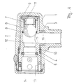
- a tubular rotary valve 2 is rotatably mounted about its longitudinal axis.
- the rotary slide valve 2 has an opening 13 on one end face, which corresponds to an opening 14 in the housing 1, through which a gas plug, which is attached to the end of a hose, can be detachably inserted.
- the gas plug not shown
- the rotary valve 2 is rotatably adjusted about its longitudinal axis, a side opening 15 in the rotary valve corresponding to an opening 16 in the housing 1 in a first position.
- This opening 16 is surrounded by a seal 3, which is used for Outside of the rotary valve 2 protrudes laterally on the housing 1 and to which the gas supply line can be connected.
- the rotary slide 2 closes the opening 16.
- a helical compression spring is mounted coaxially as a spring element 7, which rests on a ball that forms a closing part 6.
- the closing part 6 is located in a retaining ring 8, the inside diameter of the retaining ring 8 being chosen to be somewhat smaller than the outside diameter of the closing part 6, so that despite the pressure of the spring element 7, the closing part 6 remains in the position close to the bushing 11.
- the retaining ring 8 consists of a material, in particular plastic or a metal, in particular solder, which softens at a preselected, specific temperature, in particular at 650 degrees, to such an extent that the closing part is pressed by the spring element 7 through the retaining ring 8 and into the sealing seat 12 arrives and rests there sealingly. Since the sealing seat 12 is located between the openings 15, 16 or the inlet connector and the gas plug or the openings 13, 14, the gas flow is blocked by the closing part 6 being inserted in the sealing seat.
- a differently shaped rotationally symmetrical closing part in particular a cone or truncated cone, can also be used.
- seals 3 and 4 arranged on the outside of the rotary valve 2 i.e. also the seals for the gas plug arranged in the rotary valve, consist of conventional, largely heat-resistant materials
- an additional external seal in the form of the safety sealing ring 10 is arranged around the rotary valve near the seal 3 , which provides the necessary outer seal under thermal stress and consists of pure graphite. This seal is still tight when the other seals, in particular made of NBR, have melted.
Landscapes
- Engineering & Computer Science (AREA)
- General Engineering & Computer Science (AREA)
- Mechanical Engineering (AREA)
- Safety Valves (AREA)
- Pharmaceuticals Containing Other Organic And Inorganic Compounds (AREA)
- Taps Or Cocks (AREA)
- Sliding Valves (AREA)
Applications Claiming Priority (2)
| Application Number | Priority Date | Filing Date | Title |
|---|---|---|---|
| DE4220054 | 1992-06-19 | ||
| DE4220054A DE4220054C1 (enExample) | 1992-06-19 | 1992-06-19 |
Publications (2)
| Publication Number | Publication Date |
|---|---|
| EP0574677A1 EP0574677A1 (de) | 1993-12-22 |
| EP0574677B1 true EP0574677B1 (de) | 1995-12-06 |
Family
ID=6461357
Family Applications (1)
| Application Number | Title | Priority Date | Filing Date |
|---|---|---|---|
| EP93106685A Expired - Lifetime EP0574677B1 (de) | 1992-06-19 | 1993-04-24 | Sicherheitsgassteckdose |
Country Status (3)
| Country | Link |
|---|---|
| EP (1) | EP0574677B1 (enExample) |
| AT (1) | ATE131266T1 (enExample) |
| DE (2) | DE4220054C1 (enExample) |
Families Citing this family (8)
| Publication number | Priority date | Publication date | Assignee | Title |
|---|---|---|---|---|
| DE4131859A1 (de) * | 1991-09-25 | 1993-04-01 | Mertik Regelungstechnik Gmbh | Brandschutzventil mit schliessfeder zum automatischen absperren von leitungen |
| DE4422241A1 (de) * | 1994-06-24 | 1996-01-11 | Mertik Maxitrol Gmbh & Co Kg | Thermische Armaturensicherung zum automatischen Absperren von Leitungen |
| DE19608165C1 (de) * | 1996-03-04 | 1997-11-06 | Mertik Maxitrol Gmbh & Co Kg | Thermische Armaturensicherung zum automatischen Absperren von Leitungen |
| DE29706842U1 (de) * | 1997-04-16 | 1997-06-12 | Metallwerke Otto Dingerkus GmbH, 57439 Attendorn | Sicherheitshahn zum Absperren oder Steuern einer Fluidströmung, insbesondere eines Gases |
| DE19810223C1 (de) | 1998-03-10 | 1999-05-27 | Mertik Maxitrol Gmbh & Co Kg | Thermische Armaturensicherung zum automatischen Absperren von Leitungen |
| GB0418996D0 (en) * | 2004-08-25 | 2004-09-29 | Boc Group Plc | Oxygen administration apparatus |
| US8925567B2 (en) * | 2011-12-27 | 2015-01-06 | GM Global Technology Operations LLC | Thermal pressure relief device with expansion activation |
| CN111043370B (zh) * | 2018-10-11 | 2024-11-19 | 乔民 | 燃气高温切断阀 |
Family Cites Families (6)
| Publication number | Priority date | Publication date | Assignee | Title |
|---|---|---|---|---|
| GB694138A (en) * | 1951-03-16 | 1953-07-15 | Armstrong Siddeley Motors Ltd | A flow check valve |
| DE1019879B (de) * | 1954-01-27 | 1957-11-21 | Thermostatic Mixing Valve Comp | Auf Temperaturaenderungen ansprechendes Ventil |
| GB964835A (en) * | 1962-06-20 | 1964-07-22 | North Thames Gas Board | Improvements relating to safety valves |
| GB2209200A (en) * | 1987-08-28 | 1989-05-04 | Thorn Emi Flow Measurement Ltd | Thermal cut-off valve |
| DE3817971A1 (de) * | 1988-05-27 | 1989-11-30 | Streif Hans | Gasanschlussarmatur |
| DE3835904A1 (de) * | 1988-10-21 | 1990-04-26 | Waga Sicherheits & Spezial Arm | Absperrarmatur mit einer thermischen schmelzmaterial-sicherung |
-
1992
- 1992-06-19 DE DE4220054A patent/DE4220054C1/de not_active Expired - Fee Related
-
1993
- 1993-04-24 AT AT93106685T patent/ATE131266T1/de not_active IP Right Cessation
- 1993-04-24 DE DE59301076T patent/DE59301076D1/de not_active Expired - Fee Related
- 1993-04-24 EP EP93106685A patent/EP0574677B1/de not_active Expired - Lifetime
Also Published As
| Publication number | Publication date |
|---|---|
| EP0574677A1 (de) | 1993-12-22 |
| ATE131266T1 (de) | 1995-12-15 |
| DE59301076D1 (de) | 1996-01-18 |
| DE4220054C1 (enExample) | 1993-09-02 |
Similar Documents
| Publication | Publication Date | Title |
|---|---|---|
| DE60218306T2 (de) | Zylinderventil und bajonett-rückschlagfilter mit schutz gegen übermässige strömung | |
| EP1097326A2 (de) | Sicherheitseinrichtung zum absperren von gasführenden leitungssystemen | |
| EP0574677B1 (de) | Sicherheitsgassteckdose | |
| DE3010573C2 (enExample) | ||
| DE29809839U1 (de) | Gasströmungswächter | |
| EP0343615A1 (de) | Gasanschlussarmatur | |
| DE1019879B (de) | Auf Temperaturaenderungen ansprechendes Ventil | |
| EP0432371B1 (de) | Absperrhahn | |
| DE3209199A1 (de) | Absperrarmatur fuer insbesondere gasleitungen | |
| DE19813307B4 (de) | Absperrorgan mit einem Kugelhahn | |
| AT399210B (de) | Absperreinrichtung für brennbare fluide führende leitungen | |
| DE10162720A1 (de) | Absperrventil | |
| DE4423854B4 (de) | Einhebelmischventil | |
| DE1215621B (de) | Elektromagnetisch betaetigtes Gasventil fuer Gasbrenner | |
| CH693425A5 (de) | Gas-Absperrarmatur. | |
| DE976411C (de) | Dampfwasserableiter | |
| EP0363644B1 (de) | Gasanschlussarmatur | |
| DE8709338U1 (de) | Sicherheits-Absperrarmatur für eine Gasleitung | |
| DE19747497C2 (de) | Absperrorgan mit einem Kugelhahn | |
| DE4428586A1 (de) | Vorrichtung zum Auslösen und Unterbrechen des Wasserauslaufes bei einem geöffneten Wasserhahn | |
| DE3212427A1 (de) | Absperrorgan | |
| DE19837146A1 (de) | Brandschutzeinsatz für gasführende Rohrdurchgänge | |
| DE113050C (enExample) | ||
| EP0813662A1 (de) | Temperaturempfindliche absperrarmatur | |
| AT298185B (de) | Kugelhahn |
Legal Events
| Date | Code | Title | Description |
|---|---|---|---|
| PUAI | Public reference made under article 153(3) epc to a published international application that has entered the european phase |
Free format text: ORIGINAL CODE: 0009012 |
|
| AK | Designated contracting states |
Kind code of ref document: A1 Designated state(s): AT BE CH DE DK ES FR GB GR IE IT LI NL PT SE |
|
| 17P | Request for examination filed |
Effective date: 19931104 |
|
| 17Q | First examination report despatched |
Effective date: 19940330 |
|
| GRAA | (expected) grant |
Free format text: ORIGINAL CODE: 0009210 |
|
| AK | Designated contracting states |
Kind code of ref document: B1 Designated state(s): AT BE CH DE DK ES FR GB GR IE IT LI NL PT SE |
|
| PG25 | Lapsed in a contracting state [announced via postgrant information from national office to epo] |
Ref country code: NL Free format text: LAPSE BECAUSE OF FAILURE TO SUBMIT A TRANSLATION OF THE DESCRIPTION OR TO PAY THE FEE WITHIN THE PRESCRIBED TIME-LIMIT Effective date: 19951206 Ref country code: IT Free format text: LAPSE BECAUSE OF FAILURE TO SUBMIT A TRANSLATION OF THE DESCRIPTION OR TO PAY THE FEE WITHIN THE PRE;WARNING: LAPSES OF ITALIAN PATENTS WITH EFFECTIVE DATE BEFORE 2007 MAY HAVE OCCURRED AT ANY TIME BEFORE 2007. THE CORRECT EFFECTIVE DATE MAY BE DIFFERENT FROM THE ONE RECORDED.SCRIBED TIME-LIMIT Effective date: 19951206 Ref country code: GR Free format text: LAPSE BECAUSE OF FAILURE TO SUBMIT A TRANSLATION OF THE DESCRIPTION OR TO PAY THE FEE WITHIN THE PRESCRIBED TIME-LIMIT Effective date: 19951206 Ref country code: GB Effective date: 19951206 Ref country code: FR Effective date: 19951206 Ref country code: ES Free format text: THE PATENT HAS BEEN ANNULLED BY A DECISION OF A NATIONAL AUTHORITY Effective date: 19951206 Ref country code: DK Effective date: 19951206 Ref country code: BE Effective date: 19951206 |
|
| REF | Corresponds to: |
Ref document number: 131266 Country of ref document: AT Date of ref document: 19951215 Kind code of ref document: T |
|
| REG | Reference to a national code |
Ref country code: IE Ref legal event code: FG4D Free format text: 66434 |
|
| REF | Corresponds to: |
Ref document number: 59301076 Country of ref document: DE Date of ref document: 19960118 |
|
| PG25 | Lapsed in a contracting state [announced via postgrant information from national office to epo] |
Ref country code: SE Effective date: 19960306 Ref country code: PT Effective date: 19960306 |
|
| PG25 | Lapsed in a contracting state [announced via postgrant information from national office to epo] |
Ref country code: AT Effective date: 19960424 |
|
| PG25 | Lapsed in a contracting state [announced via postgrant information from national office to epo] |
Ref country code: LI Effective date: 19960430 Ref country code: CH Effective date: 19960430 |
|
| NLV1 | Nl: lapsed or annulled due to failure to fulfill the requirements of art. 29p and 29m of the patents act | ||
| EN | Fr: translation not filed | ||
| GBV | Gb: ep patent (uk) treated as always having been void in accordance with gb section 77(7)/1977 [no translation filed] |
Effective date: 19951206 |
|
| PG25 | Lapsed in a contracting state [announced via postgrant information from national office to epo] |
Ref country code: IE Free format text: LAPSE BECAUSE OF NON-PAYMENT OF DUE FEES Effective date: 19960627 |
|
| PGFP | Annual fee paid to national office [announced via postgrant information from national office to epo] |
Ref country code: DE Payment date: 19960701 Year of fee payment: 4 |
|
| REG | Reference to a national code |
Ref country code: IE Ref legal event code: FD4D Ref document number: 66434 Country of ref document: IE |
|
| PLBE | No opposition filed within time limit |
Free format text: ORIGINAL CODE: 0009261 |
|
| 26N | No opposition filed | ||
| REG | Reference to a national code |
Ref country code: CH Ref legal event code: PL |
|
| PG25 | Lapsed in a contracting state [announced via postgrant information from national office to epo] |
Ref country code: DE Free format text: LAPSE BECAUSE OF NON-PAYMENT OF DUE FEES Effective date: 19980101 |