EP0573901B1 - Système pour commander une transmission d'automobile - Google Patents
Système pour commander une transmission d'automobile Download PDFInfo
- Publication number
- EP0573901B1 EP0573901B1 EP93108963A EP93108963A EP0573901B1 EP 0573901 B1 EP0573901 B1 EP 0573901B1 EP 93108963 A EP93108963 A EP 93108963A EP 93108963 A EP93108963 A EP 93108963A EP 0573901 B1 EP0573901 B1 EP 0573901B1
- Authority
- EP
- European Patent Office
- Prior art keywords
- engine output
- engine
- controlling
- gear position
- shift command
- Prior art date
- Legal status (The legal status is an assumption and is not a legal conclusion. Google has not performed a legal analysis and makes no representation as to the accuracy of the status listed.)
- Expired - Lifetime
Links
Images


Classifications
-
- B—PERFORMING OPERATIONS; TRANSPORTING
- B60—VEHICLES IN GENERAL
- B60W—CONJOINT CONTROL OF VEHICLE SUB-UNITS OF DIFFERENT TYPE OR DIFFERENT FUNCTION; CONTROL SYSTEMS SPECIALLY ADAPTED FOR HYBRID VEHICLES; ROAD VEHICLE DRIVE CONTROL SYSTEMS FOR PURPOSES NOT RELATED TO THE CONTROL OF A PARTICULAR SUB-UNIT
- B60W10/00—Conjoint control of vehicle sub-units of different type or different function
- B60W10/04—Conjoint control of vehicle sub-units of different type or different function including control of propulsion units
- B60W10/06—Conjoint control of vehicle sub-units of different type or different function including control of propulsion units including control of combustion engines
-
- B—PERFORMING OPERATIONS; TRANSPORTING
- B60—VEHICLES IN GENERAL
- B60W—CONJOINT CONTROL OF VEHICLE SUB-UNITS OF DIFFERENT TYPE OR DIFFERENT FUNCTION; CONTROL SYSTEMS SPECIALLY ADAPTED FOR HYBRID VEHICLES; ROAD VEHICLE DRIVE CONTROL SYSTEMS FOR PURPOSES NOT RELATED TO THE CONTROL OF A PARTICULAR SUB-UNIT
- B60W10/00—Conjoint control of vehicle sub-units of different type or different function
- B60W10/10—Conjoint control of vehicle sub-units of different type or different function including control of change-speed gearings
- B60W10/11—Stepped gearings
-
- B—PERFORMING OPERATIONS; TRANSPORTING
- B60—VEHICLES IN GENERAL
- B60W—CONJOINT CONTROL OF VEHICLE SUB-UNITS OF DIFFERENT TYPE OR DIFFERENT FUNCTION; CONTROL SYSTEMS SPECIALLY ADAPTED FOR HYBRID VEHICLES; ROAD VEHICLE DRIVE CONTROL SYSTEMS FOR PURPOSES NOT RELATED TO THE CONTROL OF A PARTICULAR SUB-UNIT
- B60W30/00—Purposes of road vehicle drive control systems not related to the control of a particular sub-unit, e.g. of systems using conjoint control of vehicle sub-units, or advanced driver assistance systems for ensuring comfort, stability and safety or drive control systems for propelling or retarding the vehicle
- B60W30/18—Propelling the vehicle
- B60W30/19—Improvement of gear change, e.g. by synchronisation or smoothing gear shift
-
- B—PERFORMING OPERATIONS; TRANSPORTING
- B60—VEHICLES IN GENERAL
- B60W—CONJOINT CONTROL OF VEHICLE SUB-UNITS OF DIFFERENT TYPE OR DIFFERENT FUNCTION; CONTROL SYSTEMS SPECIALLY ADAPTED FOR HYBRID VEHICLES; ROAD VEHICLE DRIVE CONTROL SYSTEMS FOR PURPOSES NOT RELATED TO THE CONTROL OF A PARTICULAR SUB-UNIT
- B60W2710/00—Output or target parameters relating to a particular sub-units
- B60W2710/02—Clutches
- B60W2710/021—Clutch engagement state
-
- B—PERFORMING OPERATIONS; TRANSPORTING
- B60—VEHICLES IN GENERAL
- B60W—CONJOINT CONTROL OF VEHICLE SUB-UNITS OF DIFFERENT TYPE OR DIFFERENT FUNCTION; CONTROL SYSTEMS SPECIALLY ADAPTED FOR HYBRID VEHICLES; ROAD VEHICLE DRIVE CONTROL SYSTEMS FOR PURPOSES NOT RELATED TO THE CONTROL OF A PARTICULAR SUB-UNIT
- B60W2710/00—Output or target parameters relating to a particular sub-units
- B60W2710/10—Change speed gearings
- B60W2710/1005—Transmission ratio engaged
-
- F—MECHANICAL ENGINEERING; LIGHTING; HEATING; WEAPONS; BLASTING
- F16—ENGINEERING ELEMENTS AND UNITS; GENERAL MEASURES FOR PRODUCING AND MAINTAINING EFFECTIVE FUNCTIONING OF MACHINES OR INSTALLATIONS; THERMAL INSULATION IN GENERAL
- F16H—GEARING
- F16H2306/00—Shifting
- F16H2306/40—Shifting activities
- F16H2306/44—Removing torque from current gears
-
- F—MECHANICAL ENGINEERING; LIGHTING; HEATING; WEAPONS; BLASTING
- F16—ENGINEERING ELEMENTS AND UNITS; GENERAL MEASURES FOR PRODUCING AND MAINTAINING EFFECTIVE FUNCTIONING OF MACHINES OR INSTALLATIONS; THERMAL INSULATION IN GENERAL
- F16H—GEARING
- F16H2306/00—Shifting
- F16H2306/40—Shifting activities
- F16H2306/46—Uncoupling of current gear
-
- F—MECHANICAL ENGINEERING; LIGHTING; HEATING; WEAPONS; BLASTING
- F16—ENGINEERING ELEMENTS AND UNITS; GENERAL MEASURES FOR PRODUCING AND MAINTAINING EFFECTIVE FUNCTIONING OF MACHINES OR INSTALLATIONS; THERMAL INSULATION IN GENERAL
- F16H—GEARING
- F16H61/00—Control functions within control units of change-speed- or reversing-gearings for conveying rotary motion ; Control of exclusively fluid gearing, friction gearing, gearings with endless flexible members or other particular types of gearing
- F16H61/68—Control functions within control units of change-speed- or reversing-gearings for conveying rotary motion ; Control of exclusively fluid gearing, friction gearing, gearings with endless flexible members or other particular types of gearing specially adapted for stepped gearings
- F16H61/682—Control functions within control units of change-speed- or reversing-gearings for conveying rotary motion ; Control of exclusively fluid gearing, friction gearing, gearings with endless flexible members or other particular types of gearing specially adapted for stepped gearings with interruption of drive
-
- F—MECHANICAL ENGINEERING; LIGHTING; HEATING; WEAPONS; BLASTING
- F16—ENGINEERING ELEMENTS AND UNITS; GENERAL MEASURES FOR PRODUCING AND MAINTAINING EFFECTIVE FUNCTIONING OF MACHINES OR INSTALLATIONS; THERMAL INSULATION IN GENERAL
- F16H—GEARING
- F16H63/00—Control outputs from the control unit to change-speed- or reversing-gearings for conveying rotary motion or to other devices than the final output mechanism
- F16H63/40—Control outputs from the control unit to change-speed- or reversing-gearings for conveying rotary motion or to other devices than the final output mechanism comprising signals other than signals for actuating the final output mechanisms
- F16H63/50—Signals to an engine or motor
- F16H63/502—Signals to an engine or motor for smoothing gear shifts
Definitions
- the present invention relates to a transmission control system responsive to a shift control signal for effecting a gear change or shift by disengaging a synchronizing clutch for a present gear position, achieving a neutral gear position, and then engaging a synchronizing clutch for a next gear position.
- Synchronizing clutches are clutches engageable by meshing mechanical components. They include a clutch with a synchromesh mechanism, a clutch with a roller synchronizing mechanism, and a clutch with a dog tooth mechanism.
- Japanese laid-open patent publication No. JP-A 61-94830 discloses an automatic transmission for automatically carrying out gear changes with synchronizing clutches.
- an output torque transmitted through the synchronizing clutch acts to prevent the clutch from being engaged or disengaged, resulting in an increased force required to bring the gears out of mesh with each other. It is therefore necessary to disengage or engage the synchronizing clutch when the torque transmitted therethrough is eliminated and hence the force required to bring the gears out of mesh with each other is eliminated.
- a transmission actuator applies a force to a synchronizing clutch for a present gear position, which force is of a minimum level required to bring this synchronizing clutch into a neutral gear position.
- the throttle valve of an engine coupled to the automatic transmission is gradually closed to lower the output power of the engine.
- the throttle valve of the engine is gradually closed to lower the output torque of the engine gradually for allowing the gears to be brought reliably out of mesh with each other.
- the above control is effective only when the output torque of the engine is of a positive value, i.e., the engine is being accelerated, at the time the transmission starts to effect a gear change. That is, only when the output torque of the engine is of a positive value under an accelerating condition, the throttle valve is gradually closed to lower the output torque, and the neutral gear position is reached when the output torque substantially drops to a zero level, i.e., the transmission is subject to no load. If the output torque were of a negative value, i.e., the engine were being decelerated, or the output torque were zero, i.e., the transmission were under no load, at the time the transmission starts to effect a gear change, then closing the throttle valve would additionally lower the output torque of the engine. The output torque would thus not drop to zero, failing to disengage the synchronizing clutch for a present gear position.
- FR-A-2417689 discloses a method for effecting a gear shift by first reducing the torque transmitted by the gear box, then disengaging the synchronizing clutch for a present gear position and shifting to a neutral gear position and then synchronizing the input and output shafts of the transmission before engaging the synchronizing clutch for a new gear position.
- the torque transmitted by the gear box is reduced by gradually reducing the fuel injection, which might take a certain period of time.
- the engine is in a decelerated state it is accelerated for a very short period of time to reduce the torque transmitted by the gear box. It might happen that the engine traverses the no-load condition and gets into an accelerated state or that the no-load condition lasts for a period of time too short to disengage the synchronizing clutch for the present gear position.
- the unstable transmission control is problematic in that since the transmission may not effect a downshift, for example, when a downshift command is issued, the automobile may not be decelerated even though the driver wishes to decelerate the automobile through a downshift. As a result, the automobile tends to lose stability while it is running.
- Another object of the present invention is to provide a system for controlling an automobile transmission to carry out a downshift reliably and quickly based on a downshift command.
- a system for controlling an automobile transmission to effect a gear change by disengaging a synchronizing clutch means for a present gear position, achieving a neutral gear position, and then engaging a synchronizing clutch means for a next gear position in response to a shift control signal comprising a shift command means for outputting a shift command signal, an actuator for selectively engaging and disengaging the synchronizing clutch means, and an engine output adjusting means for adjusting an output power of an engine.
- the engine output adjusting means adjusts the output power of the engine, the actuator starts disengaging the synchronizing clutch means for a present gear position.
- the actuator completes disengaging the synchronizing clutch means for a present gear position to enter the neutral gear position when substantially no load is transmitted between drive and driven members of the synchronizing clutch means for a present gear position under the control of the engine output adjusting means. Thereafter, the synchronizing clutch means for a next gear position is engaged to complete the gear change.
- the engine output adjusting means is responsive to the shift command signal from the shift command means for effecting a first engine output adjusting mode to quickly lower the output power of the engine for a first period of time from the reception of the shift command signal, and effecting a second engine output adjusting mode to gradually lower the output power of the engine for a second period of time following the first period of time.
- the actuator starts disengaging the synchronizing clutch means for a present gear position and completes disengaging the synchronizing clutch means for a present gear position to enter the neutral gear position when substantially no load is transmitted between the drive and driven members of the synchronizing clutch means for a present gear position in the second engine output adjusting mode effected by the engine output adjusting means.
- the engine output adjusting means may comprise engine output generating means for generating the output power of the engine and engine output controlling means for controlling the engine output generating means.
- the engine output controlling means is responsive to the shift command signal from the shift command means for effecting a first engine output adjusting mode to shut off the engine output generating means for a first period of time from the reception of the shift command signal, and effecting a second engine output adjusting mode to intermittently shut off the engine output generating means for a second period of time following the first period of time. Responsive to the shift command signal from the shift command means, the actuator starts disengaging the synchronizing clutch means for a present gear position.
- the actuator completes disengaging the synchronizing clutch means for a present gear position to enter the neutral gear position when substantially no load is transmitted between the drive and driven members of the synchronizing clutch means for a present gear position in the second engine output adjusting mode effected by the engine output controlling means.
- the engine output generating means may comprise an ignition controlling means for controlling ignition of the engine, or a fuel injection control means for controlling fuel injection of the engine. In the first engine output adjusting mode, the ignition controlling means or the fuel injection control means is completely shut off, and in the second engine output adjusting mode, the ignition controlling means or the fuel injection control means is intermittently shut off.
- the engine output adjusting means may comprise engine output generating means for generating the output power of the engine, engine output controlling means for controlling the engine output generating means, and intake control means for adjusting the amount of intake air to be supplied to the engine.
- intake control means increases the amount of intake air and the actuator starts disengaging the synchronizing clutch means for a present gear position.
- the engine output controlling means shuts off the engine output generating means to bring the synchronizing clutch means for a present gear position into a decelerated condition for a first period of time from the reception of the shift command signal. Thereafter, the actuator completes disengaging the synchronizing clutch means for a present gear position to enter the neutral gear position when the output power of the engine is increased until no load is transmitted between the drive and driven members of the synchronizing clutch means for a present gear position.
- the engine output adjusting means may alternatively comprise engine output generating means for generating the output power of the engine, engine output controlling means for controlling the engine output generating means, a throttle valve for adjusting the amount of intake air to be supplied to the engine, a bypass intake passage for supplying intake air to the engine in bypassing relationship to the throttle valve, and bypass opening/closing means for selectively opening and closing the bypass intake passage.
- the throttle valve In response to the shift command signal from the shift command means, the throttle valve is fully closed and the bypass opening/closing means is fully opened.
- the engine output controlling means effects a first engine output adjusting mode to shut off the engine output generating means for a first period of time from the reception of the shift command signal, and a second engine output adjusting mode to intermittently shut off the engine output generating means for a second period of time following the first period of time.
- the actuator starts disengaging the synchronizing clutch means for a present gear position from the reception of the shift command signal and completes disengaging the synchronizing clutch means for a present gear position to enter the neutral gear position when substantially no load is transmitted between the drive and driven members of the synchronizing clutch means for a present gear position in the second engine output adjusting mode effected by the engine output controlling means.
- the control process carried out for speed changes by the automobile transmission control system is suitable particularly for making downshifts.
- an automobile transmission control system which is mounted on an automobile, generally comprises a multirange transmission M coupled to an in-line four-cylinder engine E through a clutch C, and an electronic control unit U (transmission controller) for controlling the transmission M.
- the engine E has a throttle valve T whose opening is controllable for varying the rotational speed of the engine E.
- the throttle valve T is associated with a throttle actuator A1 which adjusts or controls the opening of the throttle valve T and a throttle valve opening sensor S1 which detects the opening of the throttle valve T.
- the throttle actuator A1 and the throttle valve opening sensor S1 are electrically connected to the electronic control unit U.
- the clutch C is coupled to a clutch pedal Pc through a wire cable W and also to a clutch damper D having an orifice control solenoid-operated valve V.
- the clutch C can be engaged and disengaged under hydraulic pressure by the clutch damper D in response to operation of the clutch pedal Pc.
- a lever L which is movable with the clutch damper D is associated with a clutch stroke sensor S2 which detects the position of the lever L, the clutch stroke sensor S2 being electrically connected to the electronic control unit U.
- the engine E has spark plugs P and fuel injection valves F which are controlled by the electronic control unit U to control the output power produced by the engine E.
- the spark plugs P and the fuel injection valves F are electrically connected to the electronic control unit U through a spark controller M1 and a fuel supply controller M2, respectively.
- the spark controller M1, the fuel supply controller M2, and the electronic control unit U jointly control energization and de-energization of the spark plugs P and also fuel injection and fuel cutting-off through the fuel injection valves F.
- the multirange transmission M has a main shaft SM, a countershaft SC, and a plurality of gear trains disposed between the main shaft SM and the countershaft SC for establishing a desired one of gear positions.
- Each of the gear trains is combined with a roller synchronizing mechanism R for connecting the gears to the main shaft SM and the countershaft SC.
- the roller synchronizing mechanisms R are actuatable by a drum-type shift actuator A2 coupled to the electronic control unit U whose shift position is detected by a shift position sensor S3 and indicated by a shift position indicator I.
- a steering wheel H is combined with a steering shift mechanism S5 having a shift-up lever Lu for outputting an upshift command and a shift-down lever Ld for outputting a downshift command.
- the steering shift mechanism S5 is electrically connected to the electronic control unit U.
- an accelerator pedal movement sensor S4 for detecting the depressed position of an accelerator pedal PA
- an engine rotational speed sensor S5 for detecting the rotational speed of the crankshaft of the engine E
- a main shaft rotational speed sensor S6 for directly detecting the rotational speed of the main shaft SM of the multirange transmission M
- a countershaft rotational speed sensor S7 for detecting the rotational speed of the countershaft SC of the multirange transmission M through the rotational speed of an input gear operatively coupled to the countershaft SC.
- the electronic control unit U is electrically connected to a battery B that is charged by a generator G on the automobile.
- roller synchronizing mechanisms R will be described below with reference to FIGS. 2 through 5.
- the roller synchronizing mechanism R for an n th gear position has a gear 3a that is relatively rotatably supported by a needle bearing 2a on a rotatable shaft 1 which serves as either the main shaft SM or the countershaft SC of the multirange transmission M.
- the roller synchronizing mechanism R for an (n + 1) th gear position has a gear 3b that is also relatively rotatably supported by a needle bearing 2a on the rotatable shaft 1, the gear 3b being axially spaced from the gear 3a.
- a sleeve 8 is axially slidably supported on the boss 6 by splines 7.
- the gear 3a or the gear 3b is corotatably coupled the rotatable shaft 1 thus establishing the n th gear position or the (n + 1) th gear position.
- the gear 3a has an annular recess 3a1 defined in a side surface thereof, and the boss 6 has an integral ring-shaped inner cam 10a positioned in the annular recess 3a1.
- the inner cam 10a has a plurality of V-shaped cam grooves 10a1 defined in its outer circumferential surface.
- a plurality of rollers 12a are disposed respectively between the cam grooves 10a1 and a roller contact surface 3a2 on the inner circumferential surface of the recess 3a1.
- a ring-shaped retainer 13a (see FIG. 4) is disposed between the inner cam 10a and the roller contact surface 3a2 and has an outer circumferential surface relatively rotatably held in contact with the roller contact surface 3a2.
- the retainer 13a has a plurality of circumferentially spaced roller support holes 13a1 extending radially therethrough and positioned in alignment with the respective cam grooves 10a1.
- the rollers 12a are retained in the roller support holes 13a1 for slight radial movement therein.
- the retainer 13a also has three dowel insertion slots 13a2 defined in 120°-spaced relationship in an inner circumferential surface thereof, the dowel insertion slots 13a2 extending axially and opening at one side surface of the retainer 13a.
- the sleeve 8 has three dowels 8a projecting axially in 120°-spaced relationship from a side surface thereof.
- the dowels 8a move into and out of the respective dowel insertion slots 13a2 (see FIG. 5).
- the inner cam 10a and the retainer 13a are positioned as shown in FIG. 3, and the rollers 12a are fitted centrally in the cam grooves 10a1, respectively.
- the roller synchronizing mechanism R of the (n + 1) th gear position is symmetrically identical in structure to the roller synchronizing mechanism R for the n th gear position, and hence will not be described in detail below.
- the components of the roller synchronizing mechanism R for the (n + 1) th gear position are denoted by identical reference numerals with a suffix b.
- roller synchronizing mechanism R for the (n + 1) th gear position is now held in a neutral position.
- Axial movement of the sleeve 8 in the direction indicated by the arrow A in FIG. 5 places the dowels 8a out of the dowel insertion slots 13a2, thus allowing the retainer 13a and the inner cam 10a to rotate relatively to each other.
- the retainer 13a and the inner cam 10a are rotated slightly relatively to each other by a torque transmitted from the rotatable shaft 1 or the gear 3a.
- the rollers 12a are wedged radially outwardly in the roller support holes 13a1 by the respective cam grooves 10a1 and pressed against the roller contact surface 3a2.
- the inner cam 10a and the gear 3a, and hence the rotatable shaft 1 and the gear 3a are corotatably coupled to each other, establishing the n th gear position.
- the rotatable shaft 1 and the gear 3b are corotatably coupled to each other, establishing the (n + 1) th gear position.
- the shift actuator A2 will be described below with reference to FIGS. 6 and 7.
- the multirange transmission T has a casing 21 in which a cylindrical shift drum 24 is rotatably supported at its opposite ends by a pair of ball bearings 22, 23.
- a driven gear 25 fixed to one of the ends of the shift drum 24 is held in mesh with a drive gear 28 that is fixed to a drive shaft 27 of a shift motor 26 mounted on the casing 21.
- Rotation of the shift drum 24 can thus be controlled by the shift motor 26 which comprises a stepping motor in this embodiment.
- Three shift forks 30, 31, 32 have respective tubular ends 33a, 33b, 33c slidably fitted over and supported on the shift drum 24 by respective pairs of slide bearings 29.
- the shift drum 24 has three cam grooves 24a, 24b, 24c defined therein and receiving respective radial pins 34a, 34b, 34c mounted on the tubular ends 33a, 33b, 33c of the respective shift forks 30, 31, 32.
- the shift forks 30, 31, 32 have respective tip ends 9a, 9b, 9c positioned remotely from the tubular ends 33a, 33b, 33c thereof and engaging respective three sleeves 8 (see FIG. 2) of the corresponding roller synchronizing mechanisms R.
- the transmission M has five roller synchronizing mechanisms R for establishing five forward gear positions, i.e., LOW, 2ND, 3RD, 4TH, and 5TH gear positions.
- five roller synchronizing mechanisms R are arranged in pairs as shown in FIGS. 2 through 5, and used to establish the LOW, 2ND, 3RD, and 4TH gear positions, respectively.
- the other roller synchronizing mechanism R comprises one of the two mechanisms shown in FIG. 2, and is used to establish the 5TH gear position.
- N (neutral) gear position for example, the pins 34a, 34b, 34c are positioned in the respective cam grooves 24a, 24b, 24c as shown in FIG. 7.
- the pins 34a, 34b, 34c move in and along the respective cam grooves 24a, 24b, 24c, axially moving the corresponding shift forks 30, 31, 32 to successively establish the corresponding gear positions.
- the shift drum 24 rotates in the direction indicated by the arrow C in FIG. 7 to bring the pins 34a, 34b, 34c to a position LOW in FIG. 7, only the pin 34a moves to the right, moving the shift fork 30 to the right.
- the shift fork 30 actuates the roller synchronizing mechanism R for the LOW gear position to establish the LOW gear position.
- the shift motor 2 controls rotation of the shift drum 24 to control gear changes in the transmission control system.
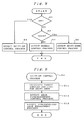
- steps S1, S2 of the gear-change control sequence determine whether there is an upshift or downshift command signal from the shift-up lever Lu or the shift-down lever Ld of the steering shift mechanism S5, i.e., whether the driver of the automobile has operated on the shift-up lever Lu or the shift-down lever Ld.
- the engine E is controlled according to a normal control process in a step S3.
- the electronic control unit U operates the throttle actuator A1 to control the engine E based on an output signal from the accelerator pedal movement sensor S4 which detects the depressed position of the accelerator pedal sensor PA.
- control goes from the step S2 to a step S4 for a shift-up control process. If a downshift command signal is produced by the shift-down lever Ld, then control goes from the step S2 to a step S5 for a shift-down control process.
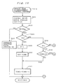
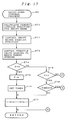
- a shift target value i.e., a target angular position for the shift drum 24 to reach with the shift motor 26 is calculated from the type of the produced upshift command signal in a step S11. Then, a step S12 carries out a gear disengagement control process for releasing the roller synchronizing mechanism R that is establishing the present n th gear position.
- step S12 The gear disengagement control process in the step S12 will be described in detail with reference to a flowchart shown in FIGS. 10 through 12 and timing charts shown in FIGS. 14(a) through 14(d).
- the angular position of the shift motor 26 is controlled based on the calculated shift target value in a step S21.
- the shift motor 26 is energized to cause the shift drum 24 to start rotating, with a slight time lag, from a position SP(P) (see FIG. 14(b)) corresponding to the present n th gear position toward a position corresponding to the next (n + 1) th gear position which is to be achieved.
- the sleeve 8 does not axially move and hence the dowels 8a do not enter the dowel insertion slots 13a2 because of frictional forces due to the drive torque being transmitted.
- the shift fork 30 (31, 32) moves as indicated by SP(1) in FIG. 14(b) by an interval corresponding to the play between the shift fork and the sleeve 8, and then stops after having reached a position SP(2).
- the sleeve 8 does not move while it is subjected to an axial push from the shift motor 26, and the dowels 8a are positioned out of the dowel insertion slots 13a2.
- the roller synchronizing mechanism R for the present n th gear position thus remains engaged.
- a step S22 determines whether the throttle valve opening TH as detected by the throttle valve opening sensor S1 is greater than a non-load throttle valve opening THNL.
- Such a detection is based on the graph of FIG. 13 which shows a non-load line LNL where the output torque TQ of the engine E at the roller synchronizing mechanism R for the present gear position is zero, i.e., no load is transmitted between drive and driven members of the roller synchronizing mechanism R for the present gear position, based on the relationship between the throttle valve opening TH and the engine rotational speed Ne.
- the throttle valve opening on the non-load line LNL represents the non-load throttle valve opening THNL. Whether the detected throttle valve opening TH is greater than the non-load throttle valve opening THNL can be determined by comparing the detected throttle valve opening TH with the non-load throttle valve opening THNL.
- the throttle valve opening TH When the throttle valve opening TH is larger than the non-load throttle valve opening THNL, then the engine E is in an accelerated condition, and the drive torque is transmitted from the engine E to the drive road wheels, i.e., from the main shaft SM through transmission gears to the countershaft SC.
- the throttle valve opening TH is smaller than the non-load throttle valve opening THNL, then the engine E is in a decelerated condition, and the drive torque is transmitted from the drive road wheels to the engine E, i.e., from the countershaft SC through transmission gears to the main shaft SM.
- the roller synchronizing mechanism R for the present gear position is first brought into an accelerated condition, and then the output power of the engine is lowered until the output torque TQ of the engine E at the roller synchronizing mechanism R for the present gear position becomes zero, i.e., no load is transmitted between drive and driven members of the roller synchronizing mechanism R for the present gear position, when the roller synchronizing mechanism R for the present gear position is disengaged.
- control goes to a step S23 in which the throttle valve opening TH is increased to an opening (THNL + ⁇ ) greater than the non-load throttle valve opening THNL for bringing the synchronizing mechanism R for the present gear position into an accelerated condition.
- the flag F F
- control goes from the step S24 through a step S28 which determines whether the flag F is 1 or not, and a step S29 which determines whether the time TIME1 is 0 or not to the step S27. This loop is repeated until the time TIME1 elapses.
- control goes from the step S24 through a step S34 which determines whether the flag F is 2 or not, and a step S35 which determines whether the time TIME2 is 0 or not to the step S32 for initially cutting off the fuel injection once during the time to which the cut-off timer TIME2 is set. This loop is repeated until the time TIME2 elapses.
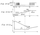
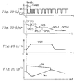
- FIGS. 14(a) through 14(d) The above control process is illustrated in FIGS. 14(a) through 14(d).
- a shift-up command signal is issued at a time t0
- the delay time TIME1 of the delay timer TIME1 up to a time t1 is awaited.
- the fuel injection is initially cut off during the time TIME2 of the cut-off timer TIME2, i.e., from the time t1 to a time t3.
- the fuel injection is intermittently cut off repeatedly at a predetermined period.
- the output power of the engine E is greatly lowered, i.e., the rotational speed Ne of the engine E is quickly lowered as indicated by Ne(1) in FIG. 14(c), and the output torque TQ at the roller synchronizing mechanism R for the present gear position is quickly lowered as indicated by TQ(1) in FIG. 14(d).
- the engine rotational speed Ne and the engine output torque TQ are gradually lowered as indicated by Ne(2) in FIG. 14(c) and TQ(2) in FIG. 14(d).
- the output torque TQ at the roller synchronizing mechanism R for the present gear position rapidly approaches a zero torque level at which no load is transmitted between the drive and driven members of the roller synchronizing mechanism R. After the output torque TQ reaches a level close to the zero torque level, it gradually approaches the zero torque level.
- the above control process for cutting off the fuel injection is effected to eliminate the output torque TQ at the roller synchronizing mechanism R for the present gear position, i.e., to eliminate any load between the drive and driven members of the roller synchronizing mechanism R. If the time during which the fuel injection is cut off were too long, however, the output torque TQ would be lowered excessively, allowing the engine to be driven from the drive road wheels.
- the time during which the fuel injection is to be cut off is set depending on the magnitude of the engine output power before the fuel injection is cut off. Specifically, the greater the engine output power, the longer the initial cut-off time is set.
- the initial cut-off time may be determined in advance with respect to the output torque TQ when the fuel injection starts to be cut off, or may be selected such that the fuel injection is cut off until the engine rotational speed drops a certain speed, e.g., 300 rpm.
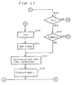
- a step S42 determines whether or not the absolute value of the difference ⁇ SP is equal to or smaller than a first predetermined value DS1 ( ⁇ SP ⁇ DS1) to determine whether the sleeve 8 has started to move or not.
- the first predetermined value DS1 is selected to be slightly smaller than the difference between the position SP(2) and the neutral position SP(N).
- control proceeds to a step S43 in which the intermittent cutting-off of the fuel injection is stopped and the fuel injection is continuously cut off.
- step S12 When the roller synchronizing mechanism R for the present n th gear position is brought into a neutral condition by the gear disengagement control process in the step S12, control proceeds to a step S13 which carries out a synchronized gear engagement control process.
- FIGS. 16(a) through 16(c) are timing charts of the synchronized gear engagement control process in its entirety, and FIGS. 14(a) through 14(d) show an initial portion of the synchronized gear engagement control process in which the roller synchronizing mechanism for the present gear position is disengaged to achieve the neutral condition.
- FIG. 16(c) shows the rotational speed Nm of the main shaft SM and the rotational speed Nc of the countershaft SC as they vary with time, the rotational speeds Nm, Nc being shown as converted into those of one shaft in the gear position at the time.
- the rotational speeds Nm, Nc are the same as each other.
- the rotational speeds Nm, Nc change to rotational speeds corresponding to the next gear position, i.e., the (n + 1) th gear position, the rotational speed Nc of the countershaft SC is lowered.
- the rotational speed Nm of the main shaft SM is equal to the engine rotational speed as long as the clutch C is engaged.
- a step S51 calculates the difference ⁇ Ns between the rotational speeds Nm, Nc, and then a step S52 determines whether or not the difference ⁇ Ns is equal to or lower than a predetermined difference DN.
- a step S54 calculates the positional difference ⁇ SP between the actual shift fork position SP and the next shift fork position SP(n).
- a step S55 determines whether or not the absolute value of the positional difference ⁇ SP is equal to or greater than a second predetermined value DS2. If
- a fuel injection control signal of one period having a predetermined fuel cut-off time I(CUT) is issued in the steps S58, S59. Then, a fuel injection control signal of one period having a predetermined fuel cutoff time which is shorter than the fuel cut-off time I(CUT) by ⁇ I is issued in the step S60. This loop is repeated to gradually reduce the fuel cut-off time.
- I(CUT) ⁇ the normal fuel injection process is resumed in the steps S57, S61.
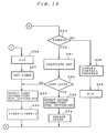
- a shift target value i.e., a target angular position for the shift drum 24 to reach with the shift motor 26 is calculated from the type of the produced upshift command signal in a step S71. Then, a gear disengagement control process for releasing the roller synchronizing mechanism R that is establishing the present (n + 1) th gear position.
- the angular position of the shift motor 26 is controlled based on the calculated shift target value in a step S72.
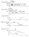
- the shift motor 26 is energized to cause the shift drum 24 to start rotating, with a slight time lag, from the position SP(P) (see FIG. 20(b)) corresponding to the present (n + 1) th gear position toward the position corresponding to the next n th gear position which is to be achieved.
- the sleeve 8 does not axially move and hence the dowels 8b do not enter the dowel insertion slots 13b2 because of frictional forces due to the drive torque being transmitted.
- the shift fork 30 (31, 32) moves as indicated by SP(1) in FIG. 20(b) by an interval corresponding to the play between the shift fork and the sleeve 8, and then stops after having reached a position SP(2).
- the sleeve 8 does not move while it is subjected to an axial push from the shift motor 26, and the dowels 8b are positioned out of the dowel insertion slots 13b2.
- the roller synchronizing mechanism R for the present (n + 1) th gear position thus remains engaged.
- a step S73 controls the throttle valve opening TH to reach a target opening, which is a full throttle valve opening WOT here, regardless of the condition of the accelerator pedal A.
- the roller synchronizing mechanism R for the present gear position is first brought into a decelerated condition, and then the output power of the engine is increased until the output torque TQ of the engine E at the roller synchronizing mechanism R for the present gear position becomes zero, i.e., no load is transmitted between drive and driven members of the roller synchronizing mechanism R for the present gear position, when the roller synchronizing mechanism R for the present gear position is disengaged.
- the throttle valve opening TH is thus controlled to reach the target opening WOT in the step S73 to increase the output power of the engine E.
- the drive torque is transmitted from the drive road wheels to the engine E, i.e., from the countershaft SC to the main shaft SM through transmission gears.
- the drive torque is transmitted from the engine E to the drive road wheels, i.e., from the main shaft SM to the countershaft SC.
- control goes from the step S74 through a step S78 which determines whether the flag F is 1 or not, and a step S79 which determines whether the time TIME4 is 0 or not to the step S77. This loop is repeated until the time TIME4 elapses.
- control goes from the step S74 through a step S84 which determines whether the flag F is 5 or not, and a step S85 which determines whether the time TIME5 is 0 or not to the step S82 for initially cutting off the fuel injection once during the time to which the cut-off timer TIME5 is set. This loop is repeated until the time TIME5 elapses.
- the output power of the engine E is lowered to decelerate the automobile.
- the time for which the fuel injection is initially cut off is set to a value long enough to lower the output torque of the engine into a negative value to decelerate the automobile. The greater the output power of the engine E, the longer the time TIME5 for which the fuel injection is initially cut off.
- the output power of the engine is greatly lowered to decelerate the automobile. Thereafter, the first intermittent cutting-off of the fuel injection is effected with the full throttle valve opening WOT to gradually increase the output power of the engine.
- a step S92 determines whether or not the absolute value of the difference ⁇ SP is equal to or smaller than a third predetermined value DS3 ( ⁇ SP ⁇ DS3) to determine whether the sleeve 8 has started to move or not.
- the third predetermined value DS3 is selected to be slightly smaller than the difference between the position SP(2) and the neutral position SP(N).
- control proceeds to a step S93 in which a second intermittent cutting-off of the fuel injection is effected and then a step S94 in which gears are engaged.
- the gear disengagement control process is carried out in the above manner.
- a synchronized gear engagement control process is executed in a step S94.
- the synchronized gear engagement control process is effected after the second intermittent cutting-off of the fuel injection in the step S93.
- the synchronized gear engagement control process is the same as that in the shift-up control process according to the flowchart shown in FIG. 15 except that the rotational speeds of the main shaft and countershaft vary as follows: As shown in FIG. 20(d), when a shift-down command signal is issued, the rotational speed Nc of the countershaft SC as the rotational speed corresponding to the next n th gear position becomes higher than the rotational speed Nm of the main shaft SM.
- the rotational speed Nm of the main shaft SM rises and approaches the rotational speed Nc of the countershaft SC as shown in FIG. 20(d).
- the process for controlling the second intermittent cutting-off of the fuel injection is a feedback control process for making the rotational speed Nm approach the rotational speed Nc.
- the step S51 calculates the difference ⁇ Ns between the rotational speeds Nm, Nc, and then the step S52 determines whether or not the difference ⁇ Ns is equal to or lower than the predetermined difference DN.
- the position of the shift fork 30 is changed from the present neutral position SP(N) to a next position SP(n) for the next n th gear position in the step S53.
- the shift fork 30 starts moving to the next position SP(n) at the time t4 as indicated by the curve SP(4) in FIG. 20(b).
- the step S54 calculates the positional difference ⁇ SP between the actual shift fork position SP and the next shift fork position SP(n). The step S55 then determines whether or not the absolute value of the positional difference ⁇ SP is equal to or greater than the second predetermined value DS2. If
- the throttle valve T is disposed in the intake passage of the engine E, and the throttle valve T is fully opened in the step S73 shown in FIG. 17.
- a bypass intake passage BP may be connected parallel to a main intake passage MP with a throttle valve T disposed therein, and a bypass opening/closing valve BV may be disposed in the bypass intake passage BP for selectively opening and closing the bypass intake passage BP.
- the bypass opening/closing valve BV can be opened and closed by an electromagnetic solenoid BS which is electrically connected to the electronic control unit U.
- the other details of the automobile transmission control system shown in FIG. 21 are the same as those of the automobile transmission control system shown in FIG. 1.
- the process of controlling the throttle valve opening TH to reach a target opening in the step S73 shown in FIG. 17 is carried out as follows: As shown in FIGS. 22(a) through 22(e), the throttle valve T is fully closed, and the bypass opening/closing valve BV is fully opened to supply intake air through the bypass intake passage BP to the engine E.
- the throttle valve opening control process is effected quickly because any response delay caused when the bypass opening/closing valve BV is fully opened is relatively small although a relatively large response delay is experienced when the throttle valve T is fully opened.
- a system for controlling an automobile transmission effects a gear change by disengaging synchronizing clutch means for a present gear position, achieving a neutral gear position, and then engaging a synchronizing clutch for a next gear position in response to a shift control signal.
- the automobile transmission has an actuator for selectively engaging and disengaging the synchronizing clutch.
- An electronic control unit controls an engine output adjusting assembly to adjust the output power of the engine and also controls the actuator to start disengaging the synchronizing clutch for a present gear position in response to a shift command signal.
- the electronic control unit also controls the actuator to complete disengaging the synchronizing clutch for a present gear position to enter the neutral gear position when substantially no load is transmitted between drive and driven members of the synchronizing clutch for a present gear position under the control of the engine output adjusting assembly.
Claims (14)
- Système pour commander une transmission (M) d'automobile afin d'effectuer un changement de vitesse en désengrenant des moyens d'embrayage de synchronisation (R) pour une position de vitesse en cours, en passant nu point mort (N), et en engrenant ensuite les moyens d'embrayage de synchronisation (R) pour une nouvelle position de vitesse en réponse à un signal de commande de changement de vitesse, ledit système comprenant :
des moyens de commande de changement de vitesse (Lu, Ld) pour émettre un signal de commande de changement de vitesse ;
un dispositif d'actionnement (A2) pour engrener et désengrener de façon sélective les moyens d'embrayage de synchronisation (R) ;
des moyens de réglage de la sortie du moteur pour régler la puissance de sortie d'un moteur (E); et
un moyen de commande (U) pour commander lesdits moyens de réglage de la sortie du moteur afin de régler la puissance de sortie du moteur (E) et pour commander ledit dispositif d'actionnement (A2) afin de commencer le désengrènement desdits moyens d'embrayage de synchronisation (R) pour une position de vitesse en cours en réponse eu signal de commande de changement de vitesse émis par lesdits moyens de commande de changement de vitesse (Lu, Ld) et pour commander ledit dispositif d'actionnement (A2) afin d'achever le désengrènement desdits moyens d'embrayage de synchronisation (R) pour une position de vitesse en cours pour passer eu point mort (N) lorsque pratiquement aucune charge n'est transmise entre des éléments d'entraînement et entraînés des moyens d'embrayage de synchronisation (R) pour une position de vitesse en cours sous la commande desdits moyens de réglage de la sortie du moteur,
caractérisé en ce que lesdits moyens de réglage de la sortie du moteur comprennent des moyens qui réagissent au signal de commande de changement de vitesse provenant desdits moyens de commande de changement de vitesse (Lu, Ld) pour effectuer un premier mode de réglage de la sortie du moteur pour réduire rapidement la puissance de sortie du moteur (E) pour une première période de temps à partir de la réception du signal de commande de changement de vitesse, et pour effectuer un second mode de réglage de la sortie du moteur pour augmenter progressivement la puissance de sortie du moteur (E) pour une seconde période de tempe qui suit ladite première période de temps, et dans lequel ledit moyen de commande comprend des moyens qui réagissent au signal de commande de changement de vitesse provenant desdits moyens de commande de changement de vitesse (Lu, Ld) pour commander ledit dispositif d'actionnement (A2) afin de commencer le désengrénement desdits moyens d'embrayage de synchronisation (R) pour une position de vitesse en cours et d'achever le désengrènement desdits moyens d'embrayage de synchronisation (R) pour une position de vitesse en cours pour passer au point mort (N) lorsque sensiblement aucune charge n'est transmise entre les éléments d'entraînement et entraînés des moyens d'embrayage de synchronisation (R) pour une position de vitesse en cours dans ledit second mode de réglage de la sortie du moteur effectué par lesdits moyens de réglage de la sortie du moteur. - Système selon la revendication 1, dans lequel ledit signal de commande de changement de vitesse comprend un signal de commande pour commander à la transmission (M) d'automobile d'effectuer un rétrogradage, et dans lequel, dans le cas où lesdits moyens de commande de changement de vitesse (Lu, Ld) émettent ledit signal de commande de rétrogradage, lesdits moyens de réglage de la sortie du moteur dans ledit premier mode de réglage de sortie du moteur réduisent la puissance de sortie dudit moteur (E) pour amener lesdits moyens d'embrayage de synchronisation (R) dans un état de décélération.
- Système selon la revendication 1 ou 2, dans lequel lesdits moyens de réglage de la sortie du moteur comprennent des moyens générateurs de sortie du moteur pour engendrer la puissance de sortie du moteur (E) et des moyens de commande de sortie du moteur pour commander lesdits moyens générateurs de sortie du moteur, lesdits moyens de commande de la sortie du moteur comprenant des moyens réagissant au signal de commande de changement de vitesse provenant desdits moyens de commande de changement de vitesse (Lu, Ld) pour effectuer un premier mode de réglage de la sortie du moteur afin de couper lesdits moyens générateurs de sortie du moteur pendant une première période de temps à partir de la réception du signal de commande de changement de vitesse, et pour effectuer un second mode de réglage de la sortie du moteur afin de couper de façon intermittente lesdits moyens générateurs de sortie du moteur pendant une seconde période de temps qui suit ladite première période de temps, et dans lequel lesdits moyens de commande comprennent des moyens qui réagissent au signal de commande de changement de vitesse provenant desdits moyens de commande de changement de vitesse (Lu, Ld) pour commander ledit dispositif d'actionnement (A2) afin de commencer le désengrènement desdits moyens d'embrayage de synchronisation (R) pour une position de vitesse en cours et d'achever le désengrènement desdits moyens d'embrayage de synchronisation (R) pour une position de vitesse en cours pour entrer dans la position de point mort (N) lorsque sensiblement aucune charge n'est transmise entre les éléments d'entraînement et entraînés des moyens d'embrayage de synchronisation (R) pour une position de vitesse en cours dans ledit second mode de réglage de la sortie du moteur effectué par lesdits moyens de commande de la sortie du moteur.
- Système selon la revendication 3, dans lequel lesdits moyens générateurs de sortie du moteur comprennent des moyens de commande d'allumage (M1) pour commander l'allumage du moteur (E), ledit moyen de commande (U) comprenant des moyens pour couper complètement lesdits moyens de commande d'allumage (M1) dans ledit premier mode de réglage de la sortie du moteur et pour arrêter de façon intermittente lesdits moyens de commande d'allumage (M1) dans ledit second mode de réglage de la sortie du moteur.
- Système selon la revendication 3, dans lequel lesdits moyens générateurs de la sortie du moteur comprennent des moyens de commande d'injection de carburant (M2) pour commander l'injection de carburant du moteur (E), ledit moyen de commande (U) comprenant des moyens pour couper complètement l'injection de carburant par lesdits moyens de commande d'injection de carburant (M2) dans ledit premier mode de réglage de la sortie du moteur et pour couper de façon intermittente l'injection de carburant par lesdits moyens de commande d'injection de carburant (M2) dans ledit second mode de réglage de la sortie du moteur.
- Système selon la revendication 1 ou 2, dans lequel lesdits moyens de réglage de la sortie du moteur comprennent des moyens qénérateurs de sortie du moteur pour engendrer la puissance de sortie du moteur (E), des moyens de commande de sortie du moteur pour commander lesdits moyens générateurs de sortie du moteur, et des moyens de commande d'admission (T) pour régler la quantité d'air d'admission devant alimenter le moteur (E), ledit moyen de commande (U) comprenant des moyens qui réagissent au signal de commande de changement de vitesse provenant desdits moyens de commande de changement de vitesse (Lu, Ld) pour commander lesdits moyens de commande d'admission (T) afin d'augmenter la quantité d'air d'admission et pour commander ledit dispositif d'actionnement pour commencer le désengrènement desdits moyens d'embrayage de synchronisation (R) pour une position de vitesse en cours, lesdits moyens de commande de sortie du moteur comprenant des moyens pour couper lesdits moyens générateurs de sortie du moteur afin d'amener lesdits moyens d'embrayage de synchronisation (R) pour une position de vitesse en cours dans un état de décélération pendant une première période de temps à partir de la réception du signal de commande de changement de vitesse, et ledit moyen de commande (U) comprenant des moyens pour commander ledit dispositif d'actionnement (A2) pour achever le désengrènement desdits moyens d'embrayage de synchronisation (R) pour une position de vitesse en cours afin d'entrer dans la position de point mort (N) lorsque la puissance de sortie du moteur (E) est augmentée jusqu'à ce qu'aucune charge ne soit transmise entre les éléments d'entraînement et entraînés des moyens d'embrayage de synchronisation (R) pour une position de vitesse en cours.
- Système selon la revendication 6, dans lequel lesdits moyens de commande de sortie du moteur comprennent des moyens pour effectuer un premier mode de réglage de sortie du moteur pour couper lesdits moyens générateurs de sortie du moteur pendant une première période de temps à partir de la réception du signal de commande de changement de vitesse, et pour effectuer on second mode de réglage de sortie du moteur pour couper de façon intermittente lesdits moyens générateurs de sortie du moteur pendant une seconde période de temps qui fait suite à ladite première période de temps.
- Système selon la revendication 7, dans lequel lesdits moyens générateurs de sortie du moteur comprennent des moyens de commande dallumage (M1) pour commander lallumage du moteur (E), ledit moyen de commande (U) comprenant des moyens pour couper complètement lesdits moyens de commande dallumage (M1) dans ledit premier mode de réglage de sortie du moteur et pour couper de façon intermittente lesdits moyens de commande dallumage (M1) dans ledit second mode de réglage de sortie du moteur,
- Système selon la revendication 7, dans lequel lesdits moyens générateurs de sortie du moteur comprennent des moyens de commande dinjection de carburant (M2) pour commander linjection de carburant du moteur (E), ledit moyen de commande (U) comprenant des moyens pour couper complètement linjection de carburant par lesdits moyens de commande dinjection de carburant (M2) dans ledit premier mode de réglage de sortie du moteur et pour couper de façon intermittente linjection de carburant par lesdits moyens de commande dinjection de carburant (M2) dans ledit second mode de réglage de sortie du moteur.
- Système selon la revendication 7, 8 ou 9, dans lequel ledit signal de commande de changement de vitesse comprend un signal de commande pour commander à la transmission (M) d'automobile d'effectuer un rétrogradage.
- Système selon la revendication 1 ou 2, dans lequel lesdits moyens de réglage de sortie du moteur comprennent des moyens générateurs de sortie du moteur pour engendrer la puissance de sortie du moteur (E), des moyens de commande de sortie du moteur pour commander lesdits moyens générateurs de sortie du moteur, une soupape d'étranglement (T) pour régler la quantité d'air d'admission devant être amenée au moteur (E), un passage d'admission de dérivation pour amener l'air d'admission au moteur de façon dérivée par rapport à ladite soupape d'étranglement (T), et des moyens d'ouverture/fermeture (BV) du passage de dérivation pour ouvrir et fermer de façon sélective ledit passage d'admission de dérivation, ledit moyen de commande (U) comprenant des moyens qui réagissent au signal de commande de changement de vitesse provenant desdits moyens de commande de changement de vitesse (Lu, Ld) pour fermer complètement ladite soupape d'étranglement (T) et pour ouvrir complètement ledit moyen d'ouverture/fermeture (BV) du passage de dérivation, lesdits moyens de commande de sortie du moteur comprenant des moyens pour effectuer un premier mode de réglage de sortie du moteur pour couper lesdits moyens générateurs de sortie du moteur pendant une première période de temps à partir de la réception du signal de commande de changement de vitesse, et pour effectuer un second mode de réglage de sortie du moteur pour couper de façon intermittente lesdits moyens générateurs de sortie du moteur pendant une seconde période de temps qui suit ladite première période de temps, ledit moyen de commande (U) comprenant des moyens pour commander ledit dispositif d'actionnement (A2) afin de commencer le désengrènement desdits moyens d'embrayage de synchronisation (R) pour une position de vitesse en cours à Partir de la réception du signal de commande de changement de vitesse et d'achever le désengrènement desdits moyens d'embrayage de synchronisation (R) pour une position de vitesse en cours pour entrer dans la position de point mort (N) lorsque sensiblement aucune charge n'est transmise entre les éléments d'entraînement et entraînés des moyens d'embrayage de synchronisation (R) pour une position de vitesse en cours dans ledit second mode de réglage de sortie du moteur effectué par lesdits moyens de commande de sortie du moteur.
- Système selon la revendication 11, dans lequel lesdits moyens générateurs de sortie du moteur comprennent des moyens de commande d'allumage (M1) pour commander l'allumage du moteur (E), ledit moyen de commande (U) comprenant des moyens pour couper complètement lesdits moyens de commande d'allumage (M1) dans ledit premier mode de réglage de sortie du moteur et pour couper de façon intermittente lesdits moyens de commande d'allumage (M1) dans ledit second mode de réglage de sortie du moteur.
- Système selon la revendication 11, dans lequel lesdits moyens générateurs de sortie du moteur comprennent des moyens de commande d'injection de carburant (M2) pour commander l'injection de carburant du moteur (E), ledit moyen de commande (U) comprenant des moyens pour couper complètement l'injection de carburant par lesdits moyens de commande d'injection de carburant (M2) dans ledit premier mode de réglage de sortie du moteur et pour couper de façon intermittente l'injection de carburant par lesdits moyens de commande d'injection de carburant (M2) dans ledit second mode de réglage de sortie du moteur.
- Système selon la revendication 12 ou 13, dans lequel ledit signal de commande de changement de vitesse comprend un signal de commande pour commander à la transmission (M) d'automobile d'effectuer un rétrogradage.
Applications Claiming Priority (4)
| Application Number | Priority Date | Filing Date | Title |
|---|---|---|---|
| JP176256/92 | 1992-06-10 | ||
| JP176255/92 | 1992-06-10 | ||
| JP17625592A JP3105356B2 (ja) | 1992-06-10 | 1992-06-10 | 変速機の変速制御装置 |
| JP04176256A JP3105357B2 (ja) | 1992-06-10 | 1992-06-10 | 変速機の変速制御装置 |
Publications (2)
| Publication Number | Publication Date |
|---|---|
| EP0573901A1 EP0573901A1 (fr) | 1993-12-15 |
| EP0573901B1 true EP0573901B1 (fr) | 1996-04-17 |
Family
ID=26497247
Family Applications (1)
| Application Number | Title | Priority Date | Filing Date |
|---|---|---|---|
| EP93108963A Expired - Lifetime EP0573901B1 (fr) | 1992-06-10 | 1993-06-03 | Système pour commander une transmission d'automobile |
Country Status (3)
| Country | Link |
|---|---|
| US (1) | US5456643A (fr) |
| EP (1) | EP0573901B1 (fr) |
| DE (1) | DE69302217T2 (fr) |
Families Citing this family (15)
| Publication number | Priority date | Publication date | Assignee | Title |
|---|---|---|---|---|
| JP3432843B2 (ja) * | 1992-06-02 | 2003-08-04 | 本田技研工業株式会社 | 車両の変速制御装置 |
| FR2728838B1 (fr) * | 1994-12-28 | 1997-04-25 | Asulab Sa | Dispositif de propulsion pour vehicule automobile |
| SE504717C2 (sv) * | 1996-02-07 | 1997-04-14 | Scania Cv Ab | Förfarande för korrigering av motormomentet vid växling |
| DE19845604C5 (de) * | 1998-10-05 | 2005-08-18 | Getrag Getriebe- Und Zahnradfabrik Hermann Hagenmeyer Gmbh & Cie Kg | Stufengetriebe und Verfahren zum Auslegen eines Ganges eines Stufengetriebes |
| US6173624B1 (en) * | 1998-10-23 | 2001-01-16 | Borgwarner Inc. | Integrated cam and shift fork assembly |
| FR2786842B1 (fr) * | 1998-12-04 | 2001-04-06 | Renault | Procede et dispositif de changement de vitesses a passages sous couple |
| SE520230C2 (sv) | 2001-10-31 | 2003-06-10 | Volvo Lastvagnar Ab | Stegväxlad växellåda för motorfordon |
| US6916270B2 (en) | 2002-03-27 | 2005-07-12 | Eaton Corporation | Driveline torque interrupt system |
| JP4099653B2 (ja) * | 2002-11-08 | 2008-06-11 | 三菱ふそうトラック・バス株式会社 | 機械式変速機の変速制御装置 |
| EP1847732B1 (fr) * | 2006-04-21 | 2012-06-27 | Schaeffler Technologies AG & Co. KG | Procédé et dispositif de commande d'un fonctionnement d'urgence d'un engrenage parallèle |
| CN100487284C (zh) * | 2006-08-03 | 2009-05-13 | 同济大学 | 汽车自动变速器的电控装置 |
| JP2009197823A (ja) * | 2008-02-19 | 2009-09-03 | Yamaha Motor Co Ltd | 電子制御式変速装置およびそれを備えた鞍乗型車両 |
| CN102910169B (zh) * | 2012-07-21 | 2015-07-29 | 北京工业大学 | 一种降低油耗的车辆起步控制方法 |
| JP6196270B2 (ja) * | 2015-09-18 | 2017-09-13 | 本田技研工業株式会社 | 燃料噴射制御装置 |
| DE102015223899B4 (de) * | 2015-12-01 | 2020-07-30 | Bayerische Motoren Werke Aktiengesellschaft | Verfahren zum Schalten eines Motorradgetriebes |
Citations (3)
| Publication number | Priority date | Publication date | Assignee | Title |
|---|---|---|---|---|
| FR2417689A1 (fr) * | 1978-02-15 | 1979-09-14 | Berliet Automobiles | Procede et dispositif pour la synchronisation electronique d'une boite de vitesses et la detection du rapport engage |
| FR2431642A2 (fr) * | 1978-07-18 | 1980-02-15 | Berliet Automobiles | Procede et dispositif pour la synchronisation electronique d'une boite de vitesses et la detection du rapport engage |
| EP0316679A1 (fr) * | 1987-11-20 | 1989-05-24 | Eaton Corporation | Système et procédé pour contrôler le changement de vitesse pour la propulsion d'un véhicule |
Family Cites Families (13)
| Publication number | Priority date | Publication date | Assignee | Title |
|---|---|---|---|---|
| DE2726377B2 (de) * | 1977-06-10 | 1980-10-30 | Robert Bosch Gmbh, 7000 Stuttgart | Kraftstoff-Zumessungseinrichtung für Brennkraftmaschinen |
| DE3002391C2 (de) * | 1980-01-24 | 1986-06-12 | Jung, geb. Papst, Hannelore Else, 7742 St Georgen | Schmierölsystem für Kraftfahrzeug-Brennkraftmaschinen |
| CA1161526A (fr) * | 1980-03-31 | 1984-01-31 | William J. Vukovich | Systeme regulateur d'acceleration pour transmission automatiques a arbre de renvoi |
| JPS6194830A (ja) * | 1984-10-17 | 1986-05-13 | Fujitsu Ltd | 自動変速制御方式 |
| US4680988A (en) * | 1984-11-22 | 1987-07-21 | Nissan Motor Co., Ltd. | Control for shock-free shift in an automatic transmission |
| DE3507565A1 (de) * | 1985-03-04 | 1986-09-04 | Volkswagen AG, 3180 Wolfsburg | Synchronisiereinrichtung |
| US4817451A (en) * | 1987-02-26 | 1989-04-04 | Weismann Peter H | Control mechanism for selective engagement of a free wheeling engagement mechanism |
| US4987790A (en) * | 1987-02-26 | 1991-01-29 | Weismann Peter H | Transmission |
| JPH0730721B2 (ja) * | 1988-05-18 | 1995-04-10 | マツダ株式会社 | 自動変速機付車両におけるエンジン制御装置 |
| JP2629387B2 (ja) * | 1989-12-21 | 1997-07-09 | トヨタ自動車株式会社 | 自動変速機の変速制御装置 |
| GB9001962D0 (en) * | 1990-01-29 | 1990-03-28 | Sem Group Management Limited | Improvements in gear boxes |
| US5224393A (en) * | 1990-05-11 | 1993-07-06 | Honda Giken Kogyo Kabushiki Kaisha | Electronically controlled transmission and steering wheel located shift mechanism |
| JPH04215531A (ja) * | 1990-12-10 | 1992-08-06 | Honda Motor Co Ltd | 変速制御装置 |
-
1993
- 1993-06-03 EP EP93108963A patent/EP0573901B1/fr not_active Expired - Lifetime
- 1993-06-03 DE DE69302217T patent/DE69302217T2/de not_active Expired - Fee Related
- 1993-06-10 US US08/074,949 patent/US5456643A/en not_active Expired - Lifetime
Patent Citations (3)
| Publication number | Priority date | Publication date | Assignee | Title |
|---|---|---|---|---|
| FR2417689A1 (fr) * | 1978-02-15 | 1979-09-14 | Berliet Automobiles | Procede et dispositif pour la synchronisation electronique d'une boite de vitesses et la detection du rapport engage |
| FR2431642A2 (fr) * | 1978-07-18 | 1980-02-15 | Berliet Automobiles | Procede et dispositif pour la synchronisation electronique d'une boite de vitesses et la detection du rapport engage |
| EP0316679A1 (fr) * | 1987-11-20 | 1989-05-24 | Eaton Corporation | Système et procédé pour contrôler le changement de vitesse pour la propulsion d'un véhicule |
Also Published As
| Publication number | Publication date |
|---|---|
| EP0573901A1 (fr) | 1993-12-15 |
| US5456643A (en) | 1995-10-10 |
| DE69302217T2 (de) | 1996-11-14 |
| DE69302217D1 (de) | 1996-05-23 |
Similar Documents
| Publication | Publication Date | Title |
|---|---|---|
| EP0573901B1 (fr) | Système pour commander une transmission d'automobile | |
| KR100318246B1 (ko) | 자동기계변속제어장치및방법 | |
| US6393928B1 (en) | Control device for synchronous mesh automatic transmission | |
| US7211028B2 (en) | Method of controlling a vehicle, apparatus for controlling the same, transmission and apparatus for controlling the same | |
| US6514173B2 (en) | Method and apparatus of controlling transmission system | |
| US6961647B2 (en) | Method of controlling a vehicle and system of controlling the same | |
| KR100934889B1 (ko) | 파워트레인의 제어 장치, 제어 방법, 및 그 방법을 실현시키는 프로그램을 기록한 기록 매체 | |
| JPH04215531A (ja) | 変速制御装置 | |
| JPH0715270B2 (ja) | パワートレーンの総合制御装置 | |
| JP4432962B2 (ja) | 変速機の制御装置 | |
| JPH09509237A (ja) | 統合エンジン及びトランスミッション制御システム | |
| EP0300792B1 (fr) | Dispositif de commande pour le changement de vitesse automatique | |
| CN101652586A (zh) | 车辆及用于自动变速器的控制方法和控制设备 | |
| EP1436162B1 (fr) | Appareil et procede pour commander un engrenage de changement de vitesse | |
| EP1288520B1 (fr) | Dispositif et procédure de commande d'embrayage | |
| JP6464636B2 (ja) | 車両制御装置、車両制御方法、および車両 | |
| JP3105356B2 (ja) | 変速機の変速制御装置 | |
| US20050037891A1 (en) | Transmission, and control system and control method for the transmission | |
| JP3109036B2 (ja) | 変速機の変速制御装置 | |
| JP3105357B2 (ja) | 変速機の変速制御装置 | |
| JP2968563B2 (ja) | 自動クラッチ式変速機の制御装置 | |
| CN108533738B (zh) | 车辆的变速控制装置 | |
| JP3240246B2 (ja) | 車両用油圧作動式変速機の油圧制御装置 | |
| EP3364077A1 (fr) | Dispositif de commande de changement de vitesse de véhicule | |
| JPH061165A (ja) | 変速機の変速制御装置 |
Legal Events
| Date | Code | Title | Description |
|---|---|---|---|
| PUAI | Public reference made under article 153(3) epc to a published international application that has entered the european phase |
Free format text: ORIGINAL CODE: 0009012 |
|
| AK | Designated contracting states |
Kind code of ref document: A1 Designated state(s): DE GB |
|
| 17P | Request for examination filed |
Effective date: 19931227 |
|
| 17Q | First examination report despatched |
Effective date: 19941202 |
|
| GRAH | Despatch of communication of intention to grant a patent |
Free format text: ORIGINAL CODE: EPIDOS IGRA |
|
| GRAA | (expected) grant |
Free format text: ORIGINAL CODE: 0009210 |
|
| AK | Designated contracting states |
Kind code of ref document: B1 Designated state(s): DE GB |
|
| REF | Corresponds to: |
Ref document number: 69302217 Country of ref document: DE Date of ref document: 19960523 |
|
| PLBE | No opposition filed within time limit |
Free format text: ORIGINAL CODE: 0009261 |
|
| STAA | Information on the status of an ep patent application or granted ep patent |
Free format text: STATUS: NO OPPOSITION FILED WITHIN TIME LIMIT |
|
| 26N | No opposition filed | ||
| REG | Reference to a national code |
Ref country code: GB Ref legal event code: IF02 |
|
| PGFP | Annual fee paid to national office [announced via postgrant information from national office to epo] |
Ref country code: GB Payment date: 20050601 Year of fee payment: 13 |
|
| PG25 | Lapsed in a contracting state [announced via postgrant information from national office to epo] |
Ref country code: GB Free format text: LAPSE BECAUSE OF NON-PAYMENT OF DUE FEES Effective date: 20060603 |
|
| GBPC | Gb: european patent ceased through non-payment of renewal fee |
Effective date: 20060603 |
|
| PGFP | Annual fee paid to national office [announced via postgrant information from national office to epo] |
Ref country code: DE Payment date: 20080612 Year of fee payment: 16 |
|
| PG25 | Lapsed in a contracting state [announced via postgrant information from national office to epo] |
Ref country code: DE Free format text: LAPSE BECAUSE OF NON-PAYMENT OF DUE FEES Effective date: 20100101 |