EP0573402A1 - Industrial ironing machine and method for manufacturing a bed to be used in such an ironing machine - Google Patents
Industrial ironing machine and method for manufacturing a bed to be used in such an ironing machine Download PDFInfo
- Publication number
- EP0573402A1 EP0573402A1 EP93870095A EP93870095A EP0573402A1 EP 0573402 A1 EP0573402 A1 EP 0573402A1 EP 93870095 A EP93870095 A EP 93870095A EP 93870095 A EP93870095 A EP 93870095A EP 0573402 A1 EP0573402 A1 EP 0573402A1
- Authority
- EP
- European Patent Office
- Prior art keywords
- bed
- ironing
- ironing machine
- industrial
- plates
- Prior art date
- Legal status (The legal status is an assumption and is not a legal conclusion. Google has not performed a legal analysis and makes no representation as to the accuracy of the status listed.)
- Granted
Links
Images
Classifications
-
- D—TEXTILES; PAPER
- D06—TREATMENT OF TEXTILES OR THE LIKE; LAUNDERING; FLEXIBLE MATERIALS NOT OTHERWISE PROVIDED FOR
- D06F—LAUNDERING, DRYING, IRONING, PRESSING OR FOLDING TEXTILE ARTICLES
- D06F67/00—Details of ironing machines provided for in groups D06F61/00, D06F63/00, or D06F65/00
- D06F67/08—Beds; Heating arrangements therefor
Definitions
- the present invention relates to an industrial ironing machine comprising an ironing cylinder and a bed extending substantially around half of this ironing cylinder.
- the ironing cylinder is surrounded over substantially half of its circumference, in certain cases over two-thirds thereof, by a bed which is usually heated upto the required temperature by steam for drying and ironing the goods introduced between this bed and the ironing cylinder.
- the beds of such ironing machines are always composed of a heavy steel plate which has to fit closely to the ironing cylinder. In order to allow this, the inner wall of the half-cylindrically shaped bed has to be milled and finished with the utmost care.
- Beds manufactured in this way have to be milled and finished carefully due to the stresses caused by the welding process so as to guarantee the required extremely smooth finishing of the inner wall of the bed.
- An object of the invention is now to design an industrial ironing machine, the bed of which offers at least the following advantages distinguishing this component of the ironing machine clearly from that according to said French patent :
- the bed of the industrial ironing machine is composed of flexible stainless steel plates having a laser weld along the circumference and a series of welded spots so that both plates are connected to one another along their edges and locally, and both the weld and the welded spots are obtained by laser welding.
- the plate which engages in the operative position the ironing cylinder has a thickness of between 3 and 5 mm, while the plate which is situated in the operative position on the outer side, has a thickness of between 0.80 and 1.20 mm.
- the invention also relates to the method for manufacturing a bed to be used in combination with the ironing cylinder of an industrial ironing machine according to the invention.
- This method is mainly characterized in that these plates are joined along their circumference by a weld obtained through the laser technique and are further mutually connected by welded spots, which welded spots are also obtained by the laser technique, and finally the plate of the smallest thickness is deformed by injection of water under pressure until a spacing of about 2 mm is realized between both plates.
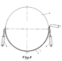
- Figure 1 is a schematically shown side elevational view of the ironing cylinder together with the bed pertaining thereto and means for keeping the bed pressed against the ironing cylinder.
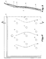
- Figure 2 shows schematically a possible distribution of the welded spots between both plates pertaining to the bed according to the invention.
- Figure 3 is a cross-section according to line III-III of Figure 2.
- the bed shown by the different figures is a bed pertaining to an ironing machine, the ironing cylinder of which has a large diameter.
- large diameter there is meant a diameter comprised between about 600 and 1600 mm.
- the problem with such large ironing cylinders consists in obtaining a closely fitting of the bed around the ironing roller. A closely fitting of these two components is a clear requisite for obtaining a remaining correct functioning of the machine.
- the clothing of the ironing roller is subject to wear. This wear, especially when it is locally more pronounced for one reason or another, is the origin of serious difficulties. Such problems regularly arise with beds having a high rigidity and a lack of deformability.
- the method for manufacturing the bed according to the invention consists in superimposing the plates 1 and 2 in a flat position and connecting them to one another by a laser weld 4 along the circumference and connecting them further locally to one another also by making use of a laser beam and this according to an arbitrary pattern.
- Figures 2 and 3 show a series of such welded spots 5.
- a pressure is built up to about 30 bars by injection of pressurized water between the plates 1 and 2, so that the thinner plate 1 will deform whereas the plate 2 maintains its continuous cross-profile.
- flow channels for the circulating fluid usually steam, are formed.
- the distance between the plates 1 and 2 comprises about 2 mm and composes the actual steam chamber.
- the plates 1 and 2 connected to one another in this way constitute a flexible entity which can be raised and be maintained in a position wherein they are pushed against the outer wall of the ironing cylinder by hydraulic jacks 6 ( Figure 1).
- this bed will closely fit against the ironing cylinder itself on the inner side, i.e. on the side of the plate 2, and this notwithstanding deformation or wear of the clothing of the ironing roller.
Abstract
Description
- The present invention relates to an industrial ironing machine comprising an ironing cylinder and a bed extending substantially around half of this ironing cylinder.
- In industrial ironing machines of the described type, the ironing cylinder is surrounded over substantially half of its circumference, in certain cases over two-thirds thereof, by a bed which is usually heated upto the required temperature by steam for drying and ironing the goods introduced between this bed and the ironing cylinder.
- The beds of such ironing machines are always composed of a heavy steel plate which has to fit closely to the ironing cylinder. In order to allow this, the inner wall of the half-cylindrically shaped bed has to be milled and finished with the utmost care.
- Beds manufactured in this way have to be milled and finished carefully due to the stresses caused by the welding process so as to guarantee the required extremely smooth finishing of the inner wall of the bed.
- In the French patent No. 1,235,155 these drawbacks are already indicated and proposes therefore to realize a bed designated as light, an essential characteristic of which being the indeformability of this component.
- The object thereof is clearly to realize a saving of weight. Due to the still relatively large thickness of the beds manufactured according to this patent and the applied conventional welding technique, the inner wall of these beds has to be subjected to the hereabove mentioned milling operations.
- An object of the invention is now to design an industrial ironing machine, the bed of which offers at least the following advantages distinguishing this component of the ironing machine clearly from that according to said French patent :
- 1. Large flexibility or deformability, which means that the bed adapts itself continuously to the ironing roller and to its clothing which is subjected to wear.
- 2. No finishing process of the inner wall is required.
- 3. A maximally performed weight reduction so that the components responsible for maintaining the necessary pressure between ironing roller and bed are less loaded.
- In order to enable this according to the invention, the bed of the industrial ironing machine is composed of flexible stainless steel plates having a laser weld along the circumference and a series of welded spots so that both plates are connected to one another along their edges and locally, and both the weld and the welded spots are obtained by laser welding.
- Still according to the invention, the plate which engages in the operative position the ironing cylinder, has a thickness of between 3 and 5 mm, while the plate which is situated in the operative position on the outer side, has a thickness of between 0.80 and 1.20 mm.
- As explained in the preamble, the invention also relates to the method for manufacturing a bed to be used in combination with the ironing cylinder of an industrial ironing machine according to the invention. This method is mainly characterized in that these plates are joined along their circumference by a weld obtained through the laser technique and are further mutually connected by welded spots, which welded spots are also obtained by the laser technique, and finally the plate of the smallest thickness is deformed by injection of water under pressure until a spacing of about 2 mm is realized between both plates.
- Other details and advantages of the invention will become apparent from the following description of an industrial ironing machine and the method for manufacturing a bed for use in such an ironing machine according to the invention. This description is only given by way of example and does not limit the scope of the invention. The reference numerals relate to the annexed figures.
- Figure 1 is a schematically shown side elevational view of the ironing cylinder together with the bed pertaining thereto and means for keeping the bed pressed against the ironing cylinder.
- Figure 2 shows schematically a possible distribution of the welded spots between both plates pertaining to the bed according to the invention.
- Figure 3 is a cross-section according to line III-III of Figure 2.
- The bed shown by the different figures is a bed pertaining to an ironing machine, the ironing cylinder of which has a large diameter. By large diameter, there is meant a diameter comprised between about 600 and 1600 mm. The problem with such large ironing cylinders consists in obtaining a closely fitting of the bed around the ironing roller. A closely fitting of these two components is a clear requisite for obtaining a remaining correct functioning of the machine. During its functioning, the clothing of the ironing roller is subject to wear. This wear, especially when it is locally more pronounced for one reason or another, is the origin of serious difficulties. Such problems regularly arise with beds having a high rigidity and a lack of deformability.
- The hereabove described drawbacks of beds used in ironing machines of large diameters can now be obviated by designing a bed which is formed by connecting two thin plates. By thin plates there are meant plates having a thickness of about 1 mm for the
plate 1 which is situated in the operative position on the outer side of the bed, and a thickness of about 4 mm of theplate 2 which, also considered in the operative position, engages theironing roller 3. - The method for manufacturing the bed according to the invention consists in superimposing the
plates welded spots 5. - After having applied the different
welded spots 5 by making use of the laser beam, a pressure is built up to about 30 bars by injection of pressurized water between theplates thinner plate 1 will deform whereas theplate 2 maintains its continuous cross-profile. Between the differentwelded spots 5, flow channels for the circulating fluid, usually steam, are formed. The distance between theplates plates - Due to the flexibility of the plates composing the bed, this bed will closely fit against the ironing cylinder itself on the inner side, i.e. on the side of the
plate 2, and this notwithstanding deformation or wear of the clothing of the ironing roller. - The advantages of the bed described within the scope of this invention can be summarized as follows :
- a) the construction of the bed is simple and cheap due to the complete omission of the technically complicated operations for milling a bed consisting of a heavy, or in anyway considerably more heavy plate than represented here,
- b) due to the connection of the thin and flexible plates trough the laser beam technique, deformations of the outer surface of the
plate 2 are avoided, which plate remains in operation always nicely in contact with the ironingcylinder 3 and this, as already emphasized hereinabove, notwithstanding possible wear or local deformations of this component. Connecting plates having a thickness in the range of 7 to 15 mm by spot welding generates stresses and therefore deformations which require expensive and time consuming milling operations. This is a very remarkable advantage since the milling operations can be omitted entirely. - c) The efficiency of the bed according to the invention can therefore be considered as being very high and reliable due to the remaining and perfect fitting of the bed against the ironing roller ;
- d) the heat transfer through a stainless steel plate having a thickness of about 4 mm is considerably better than through a steel plate of a conventional bed having a thickness of about 15 mm ;
- e) due to the very small steam content, the circulation of the hot steam does not raise the problems which are proper to wider steam chambers.
- From the hereabove given description of the ironing machine according to the invention and of the method for manufacturing the bed thereof, it appears that a flexible deformable bed which adjusts itself always to the ironing roller can be manufactured by making use of steel plates which may be considered in the relevant field as having a very small thickness. Also the welding technique suggested for this application has for result that every after treatment of the flexible bed becomes superfluous.
- The invention is not limited to the hereabove described embodiment and many modifications could be applied thereto without leaving the scope of the patent application.
Claims (5)
- An industrial ironing machine comprising an ironing cylinder and a bed extending substantially around half of this ironing cylinder, characterized in that the bed of the industrial ironing machine is composed of flexible stainless steel plates (1, 2) having besides a laser weld (4) along the circumference a series of welded spots (5) obtained by the laser technique.
- An industrial ironing machine according to claim 1, characterized in that said plate (2), which engages in the operative position the ironing cylinder (3), has a thickness of between 3 and 5 mm.
- An industrial ironing machine according to claims 1 and 2, characterized in that said plate (1), which is situated in the operative position on the outer side, has a thickness of between 0.80 and 1.20 mm.
- A method for manufacturing a bed to be used in combination with the ironing cylinder of an industrial ironing machine, which bed is composed of two stainless steel plates having a thickness of between 0.80 and 1.20 mm, on the one hand, and between 3 and 5 mm respectively, on the other hand, characterized in that these plates (1, 2) are joined along their circumference by a laser weld (4) and are further mutually connected by welded spots (5), which welded spots are also obtained by the laser technique, and finally the plate (1) of the smallest thickness is deformed by injection of water under pressure until a spacing of about 2 mm is realized between both plates.
- A method according to claim 4, characterized in that pressurized water is injected between both plates (1, 2) until a pressure of about 30 bars is built up.
Priority Applications (2)
| Application Number | Priority Date | Filing Date | Title |
|---|---|---|---|
| DE9321509U DE9321509U1 (en) | 1992-06-05 | 1993-06-04 | Commercial ironing machine |
| DE9321617U DE9321617U1 (en) | 1992-06-05 | 1993-06-04 | Commercial ironing machine |
Applications Claiming Priority (2)
| Application Number | Priority Date | Filing Date | Title |
|---|---|---|---|
| BE9200519A BE1005950A3 (en) | 1992-06-05 | 1992-06-05 | INDUSTRIAL IRONING MACHINE AND THE METHOD OF MANUFACTURING A TUB IN SUCH AN IRONING MACHINE. |
| BE9200519 | 1992-06-05 |
Publications (2)
| Publication Number | Publication Date |
|---|---|
| EP0573402A1 true EP0573402A1 (en) | 1993-12-08 |
| EP0573402B1 EP0573402B1 (en) | 1996-11-06 |
Family
ID=3886301
Family Applications (1)
| Application Number | Title | Priority Date | Filing Date |
|---|---|---|---|
| EP93870095A Revoked EP0573402B1 (en) | 1992-06-05 | 1993-06-04 | Industrial ironing machine and method for manufacturing a bed to be used in such an ironing machine |
Country Status (6)
| Country | Link |
|---|---|
| US (1) | US5438776A (en) |
| EP (1) | EP0573402B1 (en) |
| AT (1) | ATE145022T1 (en) |
| BE (1) | BE1005950A3 (en) |
| DE (1) | DE69305788T2 (en) |
| ES (1) | ES2095033T3 (en) |
Cited By (10)
| Publication number | Priority date | Publication date | Assignee | Title |
|---|---|---|---|---|
| BE1009978A3 (en) * | 1996-01-30 | 1997-11-04 | Lapauw Romain | Industrial pressing machine and method for the manufacture of the tub for this |
| EP0855459A1 (en) * | 1996-12-31 | 1998-07-29 | Kannegiesser Aue GmbH Wäschereitechnik | Bowl shaped mangle |
| EP1120488A2 (en) * | 2000-01-25 | 2001-08-01 | Kannegiesser Aue GmbH | Trough mangle |
| EP1233101A2 (en) * | 2001-02-14 | 2002-08-21 | Kannegiesser Aue GmbH | Trough mangle |
| WO2003048444A1 (en) * | 2001-12-04 | 2003-06-12 | Jensen Denmark A/S | A rotary ironer for ironing essentially rectangular pieces of cloth |
| EP1688533A1 (en) * | 2001-02-14 | 2006-08-09 | Kannegiesser Aue GmbH | Trough mangle |
| WO2010037401A1 (en) * | 2008-10-03 | 2010-04-08 | Jensen Denmark A/S | An ironer bed |
| EP2243876A1 (en) | 2009-04-24 | 2010-10-27 | Dominique Lapauw | Method for manufacturing a bed for an ironing device, a bed for an ironing device and an ironing device provided with such a bed |
| CN101748587B (en) * | 2008-12-09 | 2013-02-13 | 张家港市江南沙洲化工机械有限公司 | Heating trough of trough-type heating ironing machine |
| EP2554741B1 (en) * | 2011-08-05 | 2019-10-09 | Laco Machinery NV | Bed for ironing device |
Families Citing this family (6)
| Publication number | Priority date | Publication date | Assignee | Title |
|---|---|---|---|---|
| DE19702644A1 (en) * | 1997-01-07 | 1998-07-09 | Kannegiesser H Gmbh Co | Trough lack |
| US20060096960A1 (en) * | 2004-11-09 | 2006-05-11 | Mobile Tool Management, Inc. | Method of marking and tracking objects |
| DE102005001367C5 (en) * | 2005-01-11 | 2011-11-17 | Johnson Controls Interiors Gmbh & Co. Kg | Metal-reinforced hybrid structure |
| BE1020469A5 (en) | 2012-02-17 | 2013-11-05 | Laco Machinery N V | FAIRER FOR IRONING. |
| EP3412825B1 (en) * | 2017-06-09 | 2020-07-01 | Electrolux Laundry Systems France | Ironing machine |
| BE1028891B1 (en) | 2021-06-17 | 2022-07-11 | Laco Machinery | FAIRING FOR IRONING DEVICE |
Citations (1)
| Publication number | Priority date | Publication date | Assignee | Title |
|---|---|---|---|---|
| FR1235155A (en) * | 1959-01-12 | 1960-07-01 | Emile D Hooge S P R L Atel Con | New bowl for calender |
Family Cites Families (12)
| Publication number | Priority date | Publication date | Assignee | Title |
|---|---|---|---|---|
| DE213552C (en) * | ||||
| DE263553C (en) * | ||||
| DE820596C (en) * | 1950-04-06 | 1951-11-12 | Hans Dipl-Ing Becker | Lack of laundry trays |
| US4223202A (en) * | 1978-12-14 | 1980-09-16 | United Technologies Corporation | Apparatus and method for welding boat subassemblies utilizing laser radiation |
| US4418486A (en) * | 1981-10-27 | 1983-12-06 | Chicago Dryer Company | Heated smoothing roll |
| GB2088416B (en) * | 1981-11-03 | 1984-03-21 | Neil & Spencer Ltd | Improvements in or relating to calender ironing machines |
| FR2547756B1 (en) * | 1983-06-24 | 1986-06-06 | Sciaky Sa | LASER BEAM POINT WELDING PROCESS AND INSTALLATION |
| EP0168448A1 (en) * | 1984-01-19 | 1986-01-22 | GEIGER, Friedrich | Hot calender |
| DE8505793U1 (en) * | 1985-03-01 | 1987-11-19 | Herbert Kannegiesser Gmbh + Co, 4973 Vlotho, De | |
| FR2580680B1 (en) * | 1985-04-23 | 1987-06-26 | Dubix Sa Ets | IMPROVED BOWL IRONER |
| GB2191977B (en) * | 1986-06-24 | 1990-01-10 | Lamb Sceptre Ltd | Improvements in automobile body building methods and apparatus |
| NL8900457A (en) * | 1989-02-23 | 1990-09-17 | Hooge Nv E | DEVICE FOR IRONING LAUNDRY. |
-
1992
- 1992-06-05 BE BE9200519A patent/BE1005950A3/en not_active IP Right Cessation
-
1993
- 1993-06-04 ES ES93870095T patent/ES2095033T3/en not_active Expired - Lifetime
- 1993-06-04 US US08/071,264 patent/US5438776A/en not_active Expired - Lifetime
- 1993-06-04 EP EP93870095A patent/EP0573402B1/en not_active Revoked
- 1993-06-04 AT AT93870095T patent/ATE145022T1/en not_active IP Right Cessation
- 1993-06-04 DE DE69305788T patent/DE69305788T2/en not_active Expired - Fee Related
Patent Citations (1)
| Publication number | Priority date | Publication date | Assignee | Title |
|---|---|---|---|---|
| FR1235155A (en) * | 1959-01-12 | 1960-07-01 | Emile D Hooge S P R L Atel Con | New bowl for calender |
Cited By (16)
| Publication number | Priority date | Publication date | Assignee | Title |
|---|---|---|---|---|
| BE1009978A3 (en) * | 1996-01-30 | 1997-11-04 | Lapauw Romain | Industrial pressing machine and method for the manufacture of the tub for this |
| EP0855459A1 (en) * | 1996-12-31 | 1998-07-29 | Kannegiesser Aue GmbH Wäschereitechnik | Bowl shaped mangle |
| EP1120488A2 (en) * | 2000-01-25 | 2001-08-01 | Kannegiesser Aue GmbH | Trough mangle |
| EP1120488A3 (en) * | 2000-01-25 | 2002-07-17 | Kannegiesser Aue GmbH | Trough mangle |
| US6779285B2 (en) | 2001-02-14 | 2004-08-24 | Kannegiesser Aue Gmbh | Trough mangle |
| EP1233101A3 (en) * | 2001-02-14 | 2003-05-02 | Kannegiesser Aue GmbH | Trough mangle |
| EP1233101A2 (en) * | 2001-02-14 | 2002-08-21 | Kannegiesser Aue GmbH | Trough mangle |
| EP1688533A1 (en) * | 2001-02-14 | 2006-08-09 | Kannegiesser Aue GmbH | Trough mangle |
| WO2003048444A1 (en) * | 2001-12-04 | 2003-06-12 | Jensen Denmark A/S | A rotary ironer for ironing essentially rectangular pieces of cloth |
| WO2003048445A1 (en) * | 2001-12-04 | 2003-06-12 | Jensen Denmark A/S | A rotary ironer for ironing essentially rectangular pieces of cloth |
| WO2010037401A1 (en) * | 2008-10-03 | 2010-04-08 | Jensen Denmark A/S | An ironer bed |
| US8561327B2 (en) | 2008-10-03 | 2013-10-22 | Jensen Denmark A/S | Ironer bed |
| CN101748587B (en) * | 2008-12-09 | 2013-02-13 | 张家港市江南沙洲化工机械有限公司 | Heating trough of trough-type heating ironing machine |
| EP2243876A1 (en) | 2009-04-24 | 2010-10-27 | Dominique Lapauw | Method for manufacturing a bed for an ironing device, a bed for an ironing device and an ironing device provided with such a bed |
| BE1018731A5 (en) * | 2009-04-24 | 2011-07-05 | Lapauw Internat Nv | METHOD FOR MANUFACTURING A STEAM OR LIQUID HEATING TANK FOR A IRONING EQUIPMENT, A STEAM OR LIQUID HEATING TANK AND AN IRON PROVIDED WITH SUCH A TANK. |
| EP2554741B1 (en) * | 2011-08-05 | 2019-10-09 | Laco Machinery NV | Bed for ironing device |
Also Published As
| Publication number | Publication date |
|---|---|
| US5438776A (en) | 1995-08-08 |
| DE69305788T2 (en) | 1997-03-27 |
| DE69305788D1 (en) | 1996-12-12 |
| ES2095033T3 (en) | 1997-02-01 |
| BE1005950A3 (en) | 1994-03-15 |
| ATE145022T1 (en) | 1996-11-15 |
| EP0573402B1 (en) | 1996-11-06 |
Similar Documents
| Publication | Publication Date | Title |
|---|---|---|
| EP0573402B1 (en) | Industrial ironing machine and method for manufacturing a bed to be used in such an ironing machine | |
| EP1456593B1 (en) | A plate package, method of manufacturing a plate package and plate heat exchanger comprising a plate package | |
| EP1097011B1 (en) | A method of joining at least four heat transfer plates to a plate package, and a plate package | |
| US2214002A (en) | Welded article and method of making same | |
| US4453593A (en) | Oil-heated roller | |
| US5655397A (en) | Method for rolling a plate and rolling mill both using roll shift and roll bend and roll for use therefor | |
| JP3646695B2 (en) | Hydraulic forming apparatus and method for forming hollow structure parts made of laminated plate material, and laminated plate material | |
| EP2243876B1 (en) | Method for manufacturing a bed for an ironing device | |
| EP0742059A1 (en) | Press-forming method of a sheet and apparatus therefor | |
| US2944328A (en) | Method of making heat exchanger | |
| JPH0295471A (en) | Smoothing structure for coater | |
| WO2014040775A1 (en) | Cylinder sleeve with wear-resistant inner layer | |
| WO1999058920A1 (en) | Method of manufacturing a curved container wall | |
| US5215245A (en) | Method for roll embossing metal strip | |
| US4557791A (en) | Belt press with upper and lower bend compensators | |
| FI117447B (en) | Use of roller | |
| JPH07148396A (en) | Industrial ironing finishing machine and production of bed for use therein | |
| JPH0299253A (en) | Assembling type roll for continuous casting slab | |
| JP2709960B2 (en) | Can body structure of electric water heater and molding device therefor | |
| SU1577688A3 (en) | Machine for seam resistance welding with contact wire | |
| JP2535872B2 (en) | Flare tube manufacturing method | |
| RU2087286C1 (en) | Method of production of bimetallic vessels | |
| EP4105377A1 (en) | Trough for an ironing device | |
| US5012730A (en) | Press roll for paper machines | |
| BE1009978A3 (en) | Industrial pressing machine and method for the manufacture of the tub for this |
Legal Events
| Date | Code | Title | Description |
|---|---|---|---|
| PUAI | Public reference made under article 153(3) epc to a published international application that has entered the european phase |
Free format text: ORIGINAL CODE: 0009012 |
|
| AK | Designated contracting states |
Kind code of ref document: A1 Designated state(s): AT BE CH DE DK ES FR GB GR IE IT LI LU MC NL PT SE |
|
| 17P | Request for examination filed |
Effective date: 19940429 |
|
| 17Q | First examination report despatched |
Effective date: 19951219 |
|
| GRAG | Despatch of communication of intention to grant |
Free format text: ORIGINAL CODE: EPIDOS AGRA |
|
| GRAH | Despatch of communication of intention to grant a patent |
Free format text: ORIGINAL CODE: EPIDOS IGRA |
|
| GRAH | Despatch of communication of intention to grant a patent |
Free format text: ORIGINAL CODE: EPIDOS IGRA |
|
| GRAA | (expected) grant |
Free format text: ORIGINAL CODE: 0009210 |
|
| AK | Designated contracting states |
Kind code of ref document: B1 Designated state(s): AT BE CH DE DK ES FR GB GR IE IT LI LU MC NL PT SE |
|
| PG25 | Lapsed in a contracting state [announced via postgrant information from national office to epo] |
Ref country code: GR Free format text: LAPSE BECAUSE OF FAILURE TO SUBMIT A TRANSLATION OF THE DESCRIPTION OR TO PAY THE FEE WITHIN THE PRESCRIBED TIME-LIMIT Effective date: 19961106 Ref country code: DK Effective date: 19961106 Ref country code: AT Effective date: 19961106 |
|
| REF | Corresponds to: |
Ref document number: 145022 Country of ref document: AT Date of ref document: 19961115 Kind code of ref document: T |
|
| REG | Reference to a national code |
Ref country code: IE Ref legal event code: FG4D Free format text: 70539 |
|
| REF | Corresponds to: |
Ref document number: 69305788 Country of ref document: DE Date of ref document: 19961212 |
|
| ET | Fr: translation filed | ||
| REG | Reference to a national code |
Ref country code: ES Ref legal event code: FG2A Ref document number: 2095033 Country of ref document: ES Kind code of ref document: T3 |
|
| ITF | It: translation for a ep patent filed |
Owner name: STUDIO TECN. ING. CLAUDIO BALDI |
|
| PG25 | Lapsed in a contracting state [announced via postgrant information from national office to epo] |
Ref country code: SE Effective date: 19970206 Ref country code: PT Effective date: 19970206 |
|
| REG | Reference to a national code |
Ref country code: CH Ref legal event code: NV Representative=s name: BOVARD AG PATENTANWAELTE Ref country code: CH Ref legal event code: AEN Free format text: LA POURSUITE DE LA PROCEDURE REQUISE LE 14.03.1997 A ETE ACCORDEE. LE BREVET EST REACTIVE. |
|
| PG25 | Lapsed in a contracting state [announced via postgrant information from national office to epo] |
Ref country code: IE Free format text: LAPSE BECAUSE OF NON-PAYMENT OF DUE FEES Effective date: 19970604 |
|
| PG25 | Lapsed in a contracting state [announced via postgrant information from national office to epo] |
Ref country code: LU Free format text: LAPSE BECAUSE OF NON-PAYMENT OF DUE FEES Effective date: 19970630 |
|
| PLBQ | Unpublished change to opponent data |
Free format text: ORIGINAL CODE: EPIDOS OPPO |
|
| PLBI | Opposition filed |
Free format text: ORIGINAL CODE: 0009260 |
|
| PLBF | Reply of patent proprietor to notice(s) of opposition |
Free format text: ORIGINAL CODE: EPIDOS OBSO |
|
| 26 | Opposition filed |
Opponent name: HERBERT KANNEGIESSER GMBH + CO. Effective date: 19970806 |
|
| NLR1 | Nl: opposition has been filed with the epo |
Opponent name: HERBERT KANNEGIESSER GMBH |
|
| PLBF | Reply of patent proprietor to notice(s) of opposition |
Free format text: ORIGINAL CODE: EPIDOS OBSO |
|
| PG25 | Lapsed in a contracting state [announced via postgrant information from national office to epo] |
Ref country code: MC Effective date: 19971231 |
|
| PLBF | Reply of patent proprietor to notice(s) of opposition |
Free format text: ORIGINAL CODE: EPIDOS OBSO |
|
| PLAW | Interlocutory decision in opposition |
Free format text: ORIGINAL CODE: EPIDOS IDOP |
|
| PLAW | Interlocutory decision in opposition |
Free format text: ORIGINAL CODE: EPIDOS IDOP |
|
| PLAW | Interlocutory decision in opposition |
Free format text: ORIGINAL CODE: EPIDOS IDOP |
|
| APAC | Appeal dossier modified |
Free format text: ORIGINAL CODE: EPIDOS NOAPO |
|
| APAE | Appeal reference modified |
Free format text: ORIGINAL CODE: EPIDOS REFNO |
|
| APAC | Appeal dossier modified |
Free format text: ORIGINAL CODE: EPIDOS NOAPO |
|
| REG | Reference to a national code |
Ref country code: GB Ref legal event code: IF02 |
|
| PGFP | Annual fee paid to national office [announced via postgrant information from national office to epo] |
Ref country code: NL Payment date: 20030429 Year of fee payment: 11 Ref country code: ES Payment date: 20030429 Year of fee payment: 11 |
|
| PGFP | Annual fee paid to national office [announced via postgrant information from national office to epo] |
Ref country code: BE Payment date: 20030507 Year of fee payment: 11 |
|
| PGFP | Annual fee paid to national office [announced via postgrant information from national office to epo] |
Ref country code: GB Payment date: 20030509 Year of fee payment: 11 |
|
| PGFP | Annual fee paid to national office [announced via postgrant information from national office to epo] |
Ref country code: FR Payment date: 20030530 Year of fee payment: 11 |
|
| PGFP | Annual fee paid to national office [announced via postgrant information from national office to epo] |
Ref country code: CH Payment date: 20030610 Year of fee payment: 11 |
|
| PGFP | Annual fee paid to national office [announced via postgrant information from national office to epo] |
Ref country code: DE Payment date: 20030618 Year of fee payment: 11 |
|
| PLAB | Opposition data, opponent's data or that of the opponent's representative modified |
Free format text: ORIGINAL CODE: 0009299OPPO |
|
| APBU | Appeal procedure closed |
Free format text: ORIGINAL CODE: EPIDOSNNOA9O |
|
| R26 | Opposition filed (corrected) |
Opponent name: HERBERT KANNEGIESSER GMBH Effective date: 19970806 |
|
| RDAF | Communication despatched that patent is revoked |
Free format text: ORIGINAL CODE: EPIDOSNREV1 |
|
| RDAG | Patent revoked |
Free format text: ORIGINAL CODE: 0009271 |
|
| STAA | Information on the status of an ep patent application or granted ep patent |
Free format text: STATUS: PATENT REVOKED |
|
| NLR1 | Nl: opposition has been filed with the epo |
Opponent name: HERBERT KANNEGIESSER GMBH |
|
| REG | Reference to a national code |
Ref country code: CH Ref legal event code: PL |
|
| 27W | Patent revoked |
Effective date: 20030910 |
|
| GBPR | Gb: patent revoked under art. 102 of the ep convention designating the uk as contracting state |
Free format text: 20030910 |
|
| NLR2 | Nl: decision of opposition |
Effective date: 20030910 |
|
| APAH | Appeal reference modified |
Free format text: ORIGINAL CODE: EPIDOSCREFNO |