EP0572391B1 - System at spray dampening apparatus - Google Patents
System at spray dampening apparatus Download PDFInfo
- Publication number
- EP0572391B1 EP0572391B1 EP91905994A EP91905994A EP0572391B1 EP 0572391 B1 EP0572391 B1 EP 0572391B1 EP 91905994 A EP91905994 A EP 91905994A EP 91905994 A EP91905994 A EP 91905994A EP 0572391 B1 EP0572391 B1 EP 0572391B1
- Authority
- EP
- European Patent Office
- Prior art keywords
- dampening
- bar
- rollers
- valves
- medium
- Prior art date
- Legal status (The legal status is an assumption and is not a legal conclusion. Google has not performed a legal analysis and makes no representation as to the accuracy of the status listed.)
- Expired - Lifetime
Links
- 239000007921 spray Substances 0.000 title description 28
- 239000012530 fluid Substances 0.000 claims abstract description 36
- XLYOFNOQVPJJNP-UHFFFAOYSA-N water Substances O XLYOFNOQVPJJNP-UHFFFAOYSA-N 0.000 claims abstract description 27
- 238000007639 printing Methods 0.000 claims abstract description 17
- 238000005406 washing Methods 0.000 description 17
- 239000012528 membrane Substances 0.000 description 10
- 239000003795 chemical substances by application Substances 0.000 description 4
- 238000004140 cleaning Methods 0.000 description 3
- 229920001971 elastomer Polymers 0.000 description 3
- 239000000463 material Substances 0.000 description 3
- 238000009434 installation Methods 0.000 description 2
- 238000004519 manufacturing process Methods 0.000 description 2
- 239000002245 particle Substances 0.000 description 2
- 230000010349 pulsation Effects 0.000 description 2
- 230000004913 activation Effects 0.000 description 1
- 238000010276 construction Methods 0.000 description 1
- 238000013016 damping Methods 0.000 description 1
- 238000010586 diagram Methods 0.000 description 1
- 230000000694 effects Effects 0.000 description 1
- 239000000806 elastomer Substances 0.000 description 1
- 239000002184 metal Substances 0.000 description 1
- 239000000203 mixture Substances 0.000 description 1
- 238000007645 offset printing Methods 0.000 description 1
- 238000005192 partition Methods 0.000 description 1
- 238000004080 punching Methods 0.000 description 1
Images


Classifications
-
- B—PERFORMING OPERATIONS; TRANSPORTING
- B41—PRINTING; LINING MACHINES; TYPEWRITERS; STAMPS
- B41F—PRINTING MACHINES OR PRESSES
- B41F35/00—Cleaning arrangements or devices
-
- B—PERFORMING OPERATIONS; TRANSPORTING
- B41—PRINTING; LINING MACHINES; TYPEWRITERS; STAMPS
- B41F—PRINTING MACHINES OR PRESSES
- B41F35/00—Cleaning arrangements or devices
- B41F35/002—Cleaning arrangements or devices for dampening rollers
-
- B—PERFORMING OPERATIONS; TRANSPORTING
- B41—PRINTING; LINING MACHINES; TYPEWRITERS; STAMPS
- B41F—PRINTING MACHINES OR PRESSES
- B41F7/00—Rotary lithographic machines
- B41F7/20—Details
- B41F7/24—Damping devices
- B41F7/30—Damping devices using spraying elements
Definitions
- the present invention refers systems at printing presses and in particular to systems controlling the appliance of fluids on rollers in especially offset printing presses.
- the conventional offset press which works according to the planographic printing principle comprises four cylinders of substantially equal diameter.
- the first of the four cylinders is the plate cylinder, which supports the flexible metal printing plate, which is applied around said cylinder.
- Two sets of rollers bear on the plate cylinder, viz. on one hand damping rollers connected to a spray dampening apparatus, which dampens the printing plate when the plate cylinder rotates and on the other hand colour rollers which supply the printing colour.
- the spray dampening apparatus is constructed as a bar with nozzles, which emit dampening water against said dampening rollers.
- the plate cylinder prints the image on the surface of a second rubber-covered cylinder called offset cylinder, which bears on a third cylinder called pressure cylinder, which holds the paper against the offset cylinder when the cylinders rotate.
- offset cylinder a second rubber-covered cylinder
- pressure cylinder a third cylinder
- the printing image is not transferred directly from the plate cylinder, but via the offset cylinder on the paper web or the sheet and is fed by way of a fourth cylinder to the output of the printing press.
- a first object of the invention is to integrate a wash system with a spray dampening apparatus in such a way, that a central unit can be used for all bars and jets or nozzles.
- a second object of the invention is to provide an automatic system for washing of the plate cylinder and offset cylinder, without need for the press to be stopped at normal operation and be cleaned manually and by increased washing frequency substantially reduce the need for manual cleaning at normal service occasions.
- a third object of the invention is to provide a system comprising a control panel for said central control unit in the system, which offers the operator a clear presentation of the total status of the system and simple setting of operative parameters and which panel can be used with a minimum of knowledge of the system.
- a system at a dampening apparatus comprising spray bars, where every spray jet or nozzle in said bar forms a common outlet for a first medium in the form of dampening water and a second medium in the form of wash fluid, whereby the supply conduits of dampening water and wash fluid respectively to said nozzle are opened and closed by an electrically actuatable combination valve having two valves for respective supply conduits, the valves are individually controlled according to different operation programs from a central electronic control unit.
- a number of spray bars are actuated automatically to emit wash fluid on the dampening rollers according to a certain program stored in the control unit, when a predetermined number of offset cylinder revolutions have been recorded by said control unit.
- every valve is controlled individually, by the control panel connected to the control unit being equipped with operating means for setting of the operation cycle of every separate valve and display means with bar representation of the fluid quantity from each nozzle in a bar, the identity of which is indicated by indicator means and is connected operatively into the system by means of a first keyboard and every bar is selected for setting of every separate nozzle by means of a second keyboard.
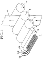
- an offset rotation press comprises a plate cylinder 5 which is dampened from a spray bar 1, by dampening rollers 3 and 4.
- a number of spray jets or nozzles are included at equal intervals, which pulse out dampening water or wash fluid in atomized form against the dampening rollers according to a certain program.
- the frequency of pulsation for dampening water depends on the speed of the press and the shape of the moisture graph.
- the pulsations in the water quantity from the spray bar is equalized by the action of the dampening rollers 3 and 4.
- Printing colour is transferred from color rollers not shown to the plate cylinder 6 with the present printing image, which is thereafter by means of the counter press cylinder 7 transferred on a running web 8.
- a spray bar 1 in a preferred embodiment of the invention comprises 8 combination valves 11A -11H which contain two separate valves which are connected to a branched conduit of an incoming pipe 51 for dampening water and a branched conduit of an incoming pipe 61 for washing fluid 61 respectively.
- Fig. 2 the spray bar acccording to Fig. 2A is shown from the nozzle side which faces the dampening roller 3. Every combination valve 11A - 11H is related to a jet or nozzle 2A - 2H, from which is received either dampening water or washing fluid in atomized form. Alternatively washing fluid and dampening water may be mixed by operating the separate valves in every combination valve in a certain way.
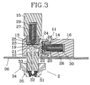
- the combination valve which is generally designated with 11, comprises a valve house 12, in which is arranged two membrane valves 13 and 14, which are actuated by each an electromagnet 15 and 16 respectively.
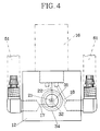
- Each valve 13, 14 comprises an inlet channel 17, 18 shown in Fig. 4 for each medium, which channels end into each a corresponding annular chamber 19, 20.
- the inlet channel 17 of the valve 13 is intended to be connected to a dampening water pipe 51, while the inlet channel 18 of the valve 14 is intended to be connected to a washing fluid pipe 61, such as is shown in Fig. 2A.
- Both fluid media are pressurized, so that respective medium is present at the inlet chambers 19, 20 respectively under a pressure of e.g. 6 bar.
- a rubber membrane 23 in the valve 13 prevents dampening water from reaching the outlet channel 21, while a rubber membrane 24 in the valve 14 prevents the washing fluid from reaching the outlet channel 22.
- the outlet channels 21 and 22 end in a common outlet channel 33 which forms the outlet for the combination valve 11.
- the valves 13 and 14 both are shown in an open position.
- the membranes 23, 24 are axially pressurized by respective springs 25, 26 and are actuable in axial direction by respective pistons 27, 28 of magnetisable material which pistons constitute armatures in the electromagnets 15 and 16 respectively.
- the pistons 27 and 28 are likewise spring loaded by means of the springs 29 and 30 respectively.
- the collected spring force of the springs 25,29 and 26,30 respectively is somewhat larger than the pressure in respective inlet chamber 19, 20, whereby the spring 25,26 acting directly on the membrane 23 and 24 respectively exert a substantially larger pressure on the membrane than the spring 29 and 30 located in the piston 27 and 28 respectively.
- the stroke of the piston 27 and 28 respectively is only some tens of a millimeter, e.g. 0,2 mm, and the springs 25,26 and 29,30 are dimensioned such that the greatest closing force is obtained from the spring 25, 26 while the spring 29, 30 in the first place has a reset function, that is, it has to reset the piston to fit-up against the membrane 23, 24 after activation of the magnet 15 and 16 respectively. In this way the otherwise usual punching effect on the membrane is avoided, that is, that the down stroke of the piston against the membrane damages the same.
- the outlet channel 33 for the combination valve 11 is formed partly by an extension tube 35, which conducts through the bottom plate 36 of the spray bar and ends in a spray nozzle 31, which is attached to the extension pipe by means of a mounting nut 34.
- the combination extension tube 35, spray jet 31 and mounting nut 34 is designated as a nozzle 2.
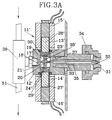
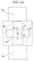
- a modified combination valve which is generally designated by 11', comprising a valve housing 12', in which is provided two valves 13' and 14', which are actuated each by an electromagnet 15' and 16' respectively.
- Each valve 13' and 14' comprises an inlet channel 17', 18' for a medium each, which channels each end in an annular chamber 19' and 20'.
- the outlet channels for respective valve coincide with each other to a common bore 21', the both ends of which form valve seats and which bore communicates with the outlet channel 33 via a channel 37 in the partition wall 38 between the annular chambers 19' and 20' and which channel 37 ends at the bottom of the valve housing 12'.
- the inlet channel 17' of the valve 13' communicates with the dampening water pipe 51 by a T- connector 39 in a thread connection in the housing 12', while the inlet channel 18' of the valve 14' in corresponding way by a T-connector 39 communicates with the washing fluid pipe 61.
- Both fluid media are pressurized so that respective medium is present in the inlet chamber 19'and 20' respectively under a pressure of e.g. 6 bar.
- a valve head 23'of an elastomer material prevents dampening water from reaching the outlet channel 21', while a valve head 24' with identical construction as 23' prevents washing fluid from reaching the outlet channel 21' which is common to the valves.
- the valves 13' and 14' both are shown in open position.
- valve heads 23' and 24' are respectively attached to a piston of magnetisable material and axially pressurized by respective springs 29',30' and actuateable in axial direction by respective pistons which constitute armatures in the solenoid magnets 15' and 16' respectively.
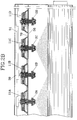
- Fig. 2B With reference to Fig. 2B is shown a central longitudinal cross section through a spray bar according to the invention, in which is shown four combination valves are connected to the dampening water pipe 51.
- the valves are opened 10 - 15 times/ sec and in such a way that two adjacent valves e.g. 11C and 11D are not open simultaneously for the jets to interfere with each other as little as possible.
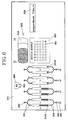
- a system of spray bars with wash function a comprises a tank installation 10, from which dampening water and wash fluid is fed through the conduits 50 and 60 respectively, which are pressurized by compressed air available on the installation site.
- the spray bars 1A-1N provided at different dampening rolls in the printing press are fed with dampening water and washing fluid with a pressure of 4-5 bar.
- Each spray bar 1A-1N containing e.g. 8 electrically in separate operable combination valves 11A-11H via operation cables 70A-70N are connected to a junction box 40, which in turn via a cable 41 is connected to interface circuits in the control unit 100, in which a microprocessor is incorporated.
- the washing function is carried out according to the following: The washing function can be initiated automatically, e.g. after a predetermined number of offset cylinder revolutions, which are detected by a revolution sensor 90 on the shaft of said cylinder, whereby the information referring to the number of revolutions is transferred to and is recorded in said control unit 100 or is initiated manually after a 24-hour shift from a control panel 101 of the control unit 100.
- dampening water in an increased quantity can be used as a rinsing agent in a washing process harmless to the environment.
- the time for the washing cycle and the amount of washing fluid which is going to be used can be programmed by the operator via the control panel 101.
- FIG. 6 With reference to Fig. 6 is shown an embodiment of the operating panel for a system according to the present invention.
- the control panel shows the operator the prevailing status or state of the system and by means of this panel the status can be changed in a simple way.
- Fig.6 also shows an example of an operational state of the system.
- the control panel 101 of the system according to the present invention in an advantageous embodiment especially adapted to the operator such that the arrangement of operating means and display means describe the various operational parameters for the system, so that no expert knowledge is required to understand how to use the equipment.
- the status information comprises the following operative parameters:
- a symbolic presentation 310 of a paper roll For indication of the current paper width, on the control panel there is a symbolic presentation 310 of a paper roll. This roll is illuminated so that it corresponds to the prevailing conditions. The example shows, that a half roll is placed on the drive side. If the operator wishes to see or change the bars being active for a full roll, the corresponding presentation, that is the roll is fully illuminated, is stepped up by means of the function button 302. Thereby on the key-board 300 is shown which bars are active for a full roll. The indicators under the switches 301 in the key-board thus are connected to seven different roll positions according to the following:
- switches 201 and 202 Through the operation switches 201 and 202 the relation between the opening and the closing times of the valves 13 and 14 in every combination valve 11 is acted on. Further switches 204 and 203 are provided for setting of the nozzles in economy and in normal operation respectively and shutting off a pair of nozzles by means of the switch 205. Thus it is possible from the panel to adjust every nozzle 2A-2H individually for the bar 1A-1N, which for the present is shown on the numerical display 320.
- operative parameters such as speed of paper, the dampening factor at the present speed of paper, the water flow, the percentual intermix of dampening water agent, the various system pressures, the present wash program etc.
Landscapes
- Engineering & Computer Science (AREA)
- Mechanical Engineering (AREA)
- Rotary Presses (AREA)
- Inking, Control Or Cleaning Of Printing Machines (AREA)
- Thermotherapy And Cooling Therapy Devices (AREA)
- Electroplating And Plating Baths Therefor (AREA)
- Electroplating Methods And Accessories (AREA)
- Spray Control Apparatus (AREA)
- Nozzles (AREA)
Abstract
Description
- The present invention refers systems at printing presses and in particular to systems controlling the appliance of fluids on rollers in especially offset printing presses.
- The conventional offset press, which works according to the planographic printing principle comprises four cylinders of substantially equal diameter. The first of the four cylinders is the plate cylinder, which supports the flexible metal printing plate, which is applied around said cylinder. Two sets of rollers bear on the plate cylinder, viz. on one hand damping rollers connected to a spray dampening apparatus, which dampens the printing plate when the plate cylinder rotates and on the other hand colour rollers which supply the printing colour. The spray dampening apparatus is constructed as a bar with nozzles, which emit dampening water against said dampening rollers. The plate cylinder prints the image on the surface of a second rubber-covered cylinder called offset cylinder, which bears on a third cylinder called pressure cylinder, which holds the paper against the offset cylinder when the cylinders rotate. Thus the printing image is not transferred directly from the plate cylinder, but via the offset cylinder on the paper web or the sheet and is fed by way of a fourth cylinder to the output of the printing press.
- With the printing press in operation the plate cylinder and the offset cylinder gradually will be covered with print colour, fluff and other undesired particles and the printing press has to be stopped for manual cleaning, which results in raised production costs. Normally cleaning of the present cylinders is carried out after every operation spell, which leads to direct production disturbances.
- A first object of the invention is to integrate a wash system with a spray dampening apparatus in such a way, that a central unit can be used for all bars and jets or nozzles.
- A second object of the invention is to provide an automatic system for washing of the plate cylinder and offset cylinder, without need for the press to be stopped at normal operation and be cleaned manually and by increased washing frequency substantially reduce the need for manual cleaning at normal service occasions.
- A third object of the invention is to provide a system comprising a control panel for said central control unit in the system, which offers the operator a clear presentation of the total status of the system and simple setting of operative parameters and which panel can be used with a minimum of knowledge of the system.
- The above objects are achieved according to the present invention by a system at a dampening apparatus comprising spray bars, where every spray jet or nozzle in said bar forms a common outlet for a first medium in the form of dampening water and a second medium in the form of wash fluid, whereby the supply conduits of dampening water and wash fluid respectively to said nozzle are opened and closed by an electrically actuatable combination valve having two valves for respective supply conduits, the valves are individually controlled according to different operation programs from a central electronic control unit.
- According to the invention a number of spray bars are actuated automatically to emit wash fluid on the dampening rollers according to a certain program stored in the control unit, when a predetermined number of offset cylinder revolutions have been recorded by said control unit.
According to the invention every valve is controlled individually, by the control panel connected to the control unit being equipped with operating means for setting of the operation cycle of every separate valve and display means with bar representation of the fluid quantity from each nozzle in a bar, the identity of which is indicated by indicator means and is connected operatively into the system by means of a first keyboard and every bar is selected for setting of every separate nozzle by means of a second keyboard. - With reference to the accompanying drawing in the following an embodiment of the present invention will be described. In the drawing
- Fig. 1 is a perspective view showing the location of a spray bar in a system according to the present invention in an offset press;
- Fig 2A is a perspective view over the valve side of a spray bar comprising 8 combination valves;
- Fig. 2 is a perspective view over the nozzle side of the spray bar according to Fig. 2A;
- Fig. 2B is a central sectional view through a spray bar showing the connnection of 4 of 8 combination valves;
- Fig. 3 is a central sectional view of a combination valve connected to nozzle in a spray bar according to the present invention;
- Fig 3A is a central sectional view of a variant of a combination valve connected to a spray bar according to the present invention;
- Fig. 4 is a view from below of the combination valve according to Fig. 3;
- Fig. 4A is a view from below of the combination valve according to Fig. 3A;
- Fig. 5 is a block diagram over a system of spray bars with washing function;
- Fig. 6 is a frontal view over the control panel of the control unit.
- With reference to Fig. 1 and what has been mentioned in the background description an offset rotation press comprises a
plate cylinder 5 which is dampened from aspray bar 1, bydampening rollers 3 and 4. In the spray bar 1 a number of spray jets or nozzles are included at equal intervals, which pulse out dampening water or wash fluid in atomized form against the dampening rollers according to a certain program. The frequency of pulsation for dampening water depends on the speed of the press and the shape of the moisture graph. The pulsations in the water quantity from the spray bar is equalized by the action of thedampening rollers 3 and 4. Printing colour is transferred from color rollers not shown to theplate cylinder 6 with the present printing image, which is thereafter by means of the counter press cylinder 7 transferred on a runningweb 8. - With reference to Fig. 2 and 2A a
spray bar 1 in a preferred embodiment of the invention comprises 8combination valves 11A -11H which contain two separate valves which are connected to a branched conduit of anincoming pipe 51 for dampening water and a branched conduit of anincoming pipe 61 forwashing fluid 61 respectively. - With reference to Fig. 2 the spray bar acccording to Fig. 2A is shown from the nozzle side which faces the
dampening roller 3.
Everycombination valve 11A - 11H is related to a jet ornozzle 2A - 2H, from which is received either dampening water or washing fluid in atomized form.
Alternatively washing fluid and dampening water may be mixed by operating the separate valves in every combination valve in a certain way. - With reference to Fig. 3 the combination valve, which is generally designated with 11, comprises a
valve house 12, in which is arranged twomembrane valves electromagnet valve inlet channel annular chamber - The
inlet channel 17 of thevalve 13 is intended to be connected to adampening water pipe 51, while theinlet channel 18 of thevalve 14 is intended to be connected to awashing fluid pipe 61, such as is shown in Fig. 2A. Both fluid media are pressurized, so that respective medium is present at theinlet chambers rubber membrane 23 in thevalve 13 prevents dampening water from reaching theoutlet channel 21, while arubber membrane 24 in thevalve 14 prevents the washing fluid from reaching theoutlet channel 22. Theoutlet channels common outlet channel 33 which forms the outlet for thecombination valve 11. In Fig. 3 thevalves - The
membranes respective springs respective pistons electromagnets - The
pistons springs springs respective inlet chamber spring membrane spring piston
The stroke of thepiston springs spring spring membrane magnet - The
outlet channel 33 for thecombination valve 11 is formed partly by anextension tube 35, which conducts through thebottom plate 36 of the spray bar and ends in aspray nozzle 31, which is attached to the extension pipe by means of amounting nut 34. Thecombination extension tube 35,spray jet 31 and mountingnut 34 is designated as anozzle 2. - With reference to fig 3A a modified combination valve is shown, which is generally designated by 11', comprising a valve housing 12', in which is provided two valves 13' and 14', which are actuated each by an electromagnet 15' and 16' respectively. Each valve 13' and 14' comprises an inlet channel 17', 18' for a medium each, which channels each end in an annular chamber 19' and 20'. The outlet channels for respective valve coincide with each other to a common bore 21', the both ends of which form valve seats and which bore communicates with the
outlet channel 33 via achannel 37 in thepartition wall 38 between the annular chambers 19' and 20' and whichchannel 37 ends at the bottom of the valve housing 12'. The inlet channel 17' of the valve 13' communicates with thedampening water pipe 51 by a T-connector 39 in a thread connection in the housing 12', while the inlet channel 18' of the valve 14' in corresponding way by a T-connector 39 communicates with thewashing fluid pipe 61. Both fluid media are pressurized so that respective medium is present in the inlet chamber 19'and 20' respectively under a pressure of e.g. 6 bar. A valve head 23'of an elastomer material prevents dampening water from reaching the outlet channel 21', while a valve head 24' with identical construction as 23' prevents washing fluid from reaching the outlet channel 21' which is common to the valves. In Fig. 3A the valves 13' and 14' both are shown in open position. The valve heads 23' and 24' are respectively attached to a piston of magnetisable material and axially pressurized by respective springs 29',30' and actuateable in axial direction by respective pistons which constitute armatures in the solenoid magnets 15' and 16' respectively. - With reference to Fig. 2B is shown a central longitudinal cross section through a spray bar according to the invention, in which is shown four combination valves are connected to the dampening
water pipe 51. In the figure the covering angle regarding atomized fluid medium which is emitted in spray form from every nozzle. The valves are opened 10 - 15 times/ sec and in such a way that two adjacent valves e.g. 11C and 11D are not open simultaneously for the jets to interfere with each other as little as possible. - With reference to Fig. 5 a system of spray bars with wash function a comprises a
tank installation 10, from which dampening water and wash fluid is fed through theconduits - Each spray bar 1A-1N containing e.g. 8 electrically in separate
operable combination valves 11A-11H viaoperation cables 70A-70N are connected to ajunction box 40, which in turn via acable 41 is connected to interface circuits in thecontrol unit 100, in which a microprocessor is incorporated.
With reference to Fig. 5 the washing function is carried out according to the following:
The washing function can be initiated automatically, e.g. after a predetermined number of offset cylinder revolutions, which are detected by arevolution sensor 90 on the shaft of said cylinder, whereby the information referring to the number of revolutions is transferred to and is recorded in saidcontrol unit 100 or is initiated manually after a 24-hour shift from acontrol panel 101 of thecontrol unit 100. - When a washing cycle starts the dampening
water valve 13 is closed and thewash fluid valve 14 is opened and closed periodically according to a predetermined program for all the bars and nozzles which have been in operation during the printing. Simultaneously with opening of the wash fluid valve being opened, the ink supply to ink rollers is shut off.
During the time of the wash cycle, the offset cylinder and the plate cylinder are cleaned by wash fluid migrating from the dampening rollers out on said cylinders and dissolves printing ink residues, which binds fluff and other undesired particles, which together with the wash fluid forms a mixture which is absorbed by the web, which is fed out as mackle. If a water based wash agent is used, dampening water in an increased quantity can be used as a rinsing agent in a washing process harmless to the environment.
The time for the washing cycle and the amount of washing fluid which is going to be used, can be programmed by the operator via thecontrol panel 101. - With reference to Fig. 6 is shown an embodiment of the operating panel for a system according to the present invention.
- The control panel shows the operator the prevailing status or state of the system and by means of this panel the status can be changed in a simple way. Fig.6 also shows an example of an operational state of the system.
- The
control panel 101 of the system according to the present invention in an advantageous embodiment especially adapted to the operator such that the arrangement of operating means and display means describe the various operational parameters for the system, so that no expert knowledge is required to understand how to use the equipment. The status information comprises the following operative parameters: - 1) Which bars are being in operation for the various paper widths. The paper width is contained as a parameter to set those nozzles which have no paper in an economy setting.
- 2) The amount of moisture, which every nozzle emits in proportion to the dampening factor. The dampening factor is a variable which follows the paper speed in the press and modifies the amount of moisture to be emitted from the nozzles.
- 3) The dampening factor at the present paper speed.
- 4) The total water flow of the whole system.
- 5) The percentual intermix of dampening water agent.
- 6) System pressure for dampening and wash fluid.
- In order to display which bars are active for the
different paper widths 40 units of illuminated membrane switches 301 constituting a keyboard designated with 300 in Fig. 6, where every illuminated switch corresponds to a bar 1A - 1N in operation. - For indication of the current paper width, on the control panel there is a
symbolic presentation 310 of a paper roll. This roll is illuminated so that it corresponds to the prevailing conditions. The example shows, that a half roll is placed on the drive side.
If the operator wishes to see or change the bars being active for a full roll, the corresponding presentation, that is the roll is fully illuminated, is stepped up by means of thefunction button 302. Thereby on the key-board 300 is shown which bars are active for a full roll. The indicators under theswitches 301 in the key-board thus are connected to seven different roll positions according to the following: - 1) Full roll;
- 2) 3/4-roll on the drive side;
- 3) 3/4-roll on the operating side;
- 4) 1/2-roll on the drive side;
- 5) 1/2-roll on the operating side;
- 6) 1/4-roll on the drive side;
- 7) 1/4-roll on the operating side.
- In order to indicate which amount of moisture or wash fluid that every
nozzle 2A-2H emits in relation of the dampening factor alternatively a wash program stored in the control unit, 8 units of standing LED-bars 210A - 210H corresponding to everynozzle 2A-2H in the bar 1A-1N which for the present is shown on the numerical display. To change a bar theswitches 321 below thenumerical display 320 are used. The length of the illuminated bar corresponds to the amount of moisture or the amount of wash fluid.
The amount of fluid emitted and thereby the height of the bar can be altered by the operator in pairs or in single for a nozzle by means of function switches "+" and "-" designated 201 and 202 at every bar. Through the operation switches 201 and 202 the relation between the opening and the closing times of thevalves combination valve 11 is acted on. Further switches 204 and 203 are provided for setting of the nozzles in economy and in normal operation respectively and shutting off a pair of nozzles by means of theswitch 205. Thus it is possible from the panel to adjust everynozzle 2A-2H individually for the bar 1A-1N, which for the present is shown on thenumerical display 320. - With reference to Fig. 6 on a display designated by 330 operative parameters such as speed of paper, the dampening factor at the present speed of paper, the water flow, the percentual intermix of dampening water agent, the various system pressures, the present wash program etc.
Claims (4)
- System for applying of fluids on rollers in an offset rotary printing press comprising at least a plate cylinder, an offset cylinder and a print cylinder and dampening rollers bearing against the plate cylinder, which dampening rollers are dampened from a number of nozzles provided on a bar in parallel to the rotation axes of said rollers and from which nozzles is emitted dampening medium in atomized form,
characterized therein,
that every nozzle (2) in said bar (1) forms a common outlet for a first medium in the form of dampening water, and a second medium in the form of wash fluid, whereby the supply pipe of dampening water (51) and the supply pipe of wash fluid (61) to said nozzle are opened and closed by means of an electrically controllable combination valve (11;11') having two valves (13,14;13',14') for the supply pipes (51,61), the valves are controlled individually according to different operation programs from a central electronic control unit (100). - System according to claim 1,
characterized therein,
that in an opening sequence of said valves (13,14;13',14') for emitting of fluid medium in atomized form the valves of two adjacent combination valves are never opened simultaneously. - System according to claim 1,
characterized therein,
that a number of bars (1A-1N) in a printing press are automatically initiated to emit wash fluid on said dampening rollers according to a certain operation program which is stored in the control unit (100), when a predetermined number of offset cylinder revolutions have been recorded by said control unit. - System according to claim 1 or 2,
characterized therein,
that the control panel (101) connected to the control unit (100) is equipped with operation means (201,202) for setting of the operation cycle of every single valve (13,14) and indicator means (210) with a bar presentation of the quantity of fluid emitted from every nozzle (2) in a bar (1), the identity of which is indicated by indicator means (320) and is connected operatively into the system by means of a first key-board (300), whereby every bar is chosen for setting of nozzles by means of a second key-board (321).
Applications Claiming Priority (3)
| Application Number | Priority Date | Filing Date | Title |
|---|---|---|---|
| SE9000780 | 1990-03-06 | ||
| SE9000780A SE465764B (en) | 1990-03-06 | 1990-03-06 | SYSTEM FOR APPLICATION OF LIQUIDS ON ROLLS IN A OFFSETROTATION PRESSURE PRESSURE |
| PCT/SE1991/000175 WO1991013760A1 (en) | 1990-03-06 | 1991-03-06 | System at spray dampening apparatus |
Publications (2)
| Publication Number | Publication Date |
|---|---|
| EP0572391A1 EP0572391A1 (en) | 1993-12-08 |
| EP0572391B1 true EP0572391B1 (en) | 1995-10-18 |
Family
ID=20378772
Family Applications (1)
| Application Number | Title | Priority Date | Filing Date |
|---|---|---|---|
| EP91905994A Expired - Lifetime EP0572391B1 (en) | 1990-03-06 | 1991-03-06 | System at spray dampening apparatus |
Country Status (9)
| Country | Link |
|---|---|
| EP (1) | EP0572391B1 (en) |
| JP (1) | JPH05505153A (en) |
| AT (1) | ATE129184T1 (en) |
| AU (1) | AU7495391A (en) |
| CA (1) | CA2077649A1 (en) |
| DE (1) | DE69114021T2 (en) |
| ES (1) | ES2080303T3 (en) |
| SE (1) | SE465764B (en) |
| WO (1) | WO1991013760A1 (en) |
Families Citing this family (12)
| Publication number | Priority date | Publication date | Assignee | Title |
|---|---|---|---|---|
| US5540390A (en) * | 1994-09-19 | 1996-07-30 | Rockwell International Corporation | Spray bar assembly for a printing press |
| DE4443357C2 (en) * | 1994-12-06 | 1998-05-14 | Roland Man Druckmasch | Method and arrangement for cleaning a cylinder of a rotary printing press |
| DE19501694A1 (en) * | 1995-01-20 | 1996-07-25 | Roland Man Druckmasch | Control for the blanket washing device of an offset rotary printing machine with several printing units |
| SE515263C2 (en) * | 1998-12-02 | 2001-07-09 | Jimek Ab | Method and apparatus for controlling the spraying of moisture in a printing press |
| DE19949906A1 (en) * | 1999-10-16 | 2001-04-19 | Baldwin Grafotec Gmbh | Printing machine cleaning device |
| CN100453188C (en) * | 2005-10-14 | 2009-01-21 | 鸿富锦精密工业(深圳)有限公司 | Equipment for depositing carbon nanotube films |
| DE102006014990B4 (en) * | 2006-03-31 | 2008-08-07 | Technotrans Ag | Spray dampening unit for printing machines and method for cleaning the at least one nozzle of a spray dampening unit |
| DE102006055584A1 (en) * | 2006-11-24 | 2008-05-29 | Man Roland Druckmaschinen Ag | Method for operating a dampening unit, dampening unit and printing unit |
| DE102007013590A1 (en) | 2007-03-21 | 2008-09-25 | Technotrans Ag | Method and device for cleaning nozzles on a spray dampening unit |
| AU2013200610B1 (en) * | 2013-02-05 | 2014-02-27 | Ecochem Australia Pty Ltd | System and method for automatically cleaning converters |
| JP6963885B2 (en) * | 2016-08-12 | 2021-11-10 | 日本ボールドウィン株式会社 | How to clean the blanket torso |
| DE102024109856A1 (en) * | 2024-04-09 | 2025-10-09 | Duma-Bandzink Gmbh | Device for applying a coating agent |
Citations (2)
| Publication number | Priority date | Publication date | Assignee | Title |
|---|---|---|---|---|
| EP0025806A1 (en) * | 1979-09-25 | 1981-04-01 | Baldwin-Gegenheimer GmbH | Device for cleaning a blanket |
| WO1989003252A1 (en) * | 1987-10-16 | 1989-04-20 | Reinhold Berntsson | A device for application of glue strips |
Family Cites Families (3)
| Publication number | Priority date | Publication date | Assignee | Title |
|---|---|---|---|---|
| US4649818A (en) * | 1985-07-22 | 1987-03-17 | Ryco Graphic Manufacturing, Inc. | Variable frequency pulsed spray dampening system |
| US4686902A (en) * | 1986-10-31 | 1987-08-18 | Precision Engineered Systems Inc. | Automatic blanket wash system |
| DE3638607A1 (en) * | 1986-11-12 | 1988-05-26 | Roland Man Druckmasch | DEVICE FOR CONTROLLING THE SUPPLY OF VARIOUS LIQUIDS |
-
1990
- 1990-03-06 SE SE9000780A patent/SE465764B/en not_active IP Right Cessation
-
1991
- 1991-03-06 JP JP3505897A patent/JPH05505153A/en active Pending
- 1991-03-06 ES ES91905994T patent/ES2080303T3/en not_active Expired - Lifetime
- 1991-03-06 CA CA002077649A patent/CA2077649A1/en not_active Abandoned
- 1991-03-06 EP EP91905994A patent/EP0572391B1/en not_active Expired - Lifetime
- 1991-03-06 DE DE69114021T patent/DE69114021T2/en not_active Expired - Fee Related
- 1991-03-06 AT AT91905994T patent/ATE129184T1/en active
- 1991-03-06 WO PCT/SE1991/000175 patent/WO1991013760A1/en not_active Ceased
- 1991-03-06 AU AU74953/91A patent/AU7495391A/en not_active Abandoned
Patent Citations (2)
| Publication number | Priority date | Publication date | Assignee | Title |
|---|---|---|---|---|
| EP0025806A1 (en) * | 1979-09-25 | 1981-04-01 | Baldwin-Gegenheimer GmbH | Device for cleaning a blanket |
| WO1989003252A1 (en) * | 1987-10-16 | 1989-04-20 | Reinhold Berntsson | A device for application of glue strips |
Also Published As
| Publication number | Publication date |
|---|---|
| EP0572391A1 (en) | 1993-12-08 |
| ES2080303T3 (en) | 1996-02-01 |
| SE9000780L (en) | 1991-09-07 |
| DE69114021D1 (en) | 1995-11-23 |
| CA2077649A1 (en) | 1991-09-07 |
| AU7495391A (en) | 1991-10-10 |
| JPH05505153A (en) | 1993-08-05 |
| DE69114021T2 (en) | 1996-05-15 |
| SE9000780D0 (en) | 1990-03-06 |
| WO1991013760A1 (en) | 1991-09-19 |
| SE465764B (en) | 1991-10-28 |
| ATE129184T1 (en) | 1995-11-15 |
Similar Documents
| Publication | Publication Date | Title |
|---|---|---|
| EP0572391B1 (en) | System at spray dampening apparatus | |
| EP0382347B1 (en) | Printing apparatus with dual inking system | |
| US4469024A (en) | Fluid dispensing apparatus such as spray dampener for printing press and method of dispensing | |
| US5213044A (en) | Method and apparatus for use in printing | |
| JP2746975B2 (en) | Spray valve device and control system | |
| US5259313A (en) | Method and apparatus for cleaning an inking mechanism and/or a printing mechanism in printing units of rotary printing machines | |
| US6205853B1 (en) | Method for testing functions of painting apparatus and apparatus for the same | |
| CA2346419A1 (en) | Painting device | |
| US3949668A (en) | Liquid feed for offset press dampening system | |
| CA2421610C (en) | Cleaning system for a rotary press and method of controlling the introduction of cleaning fluid | |
| US5839364A (en) | Dampening system for a printing press | |
| EP0335967B1 (en) | Automatic blanket wash system with flow through spray bar | |
| US20040244618A1 (en) | Flexographic printing plate cleaner | |
| JPH05330009A (en) | Dampening water feeding device for offset printer | |
| US5706723A (en) | Apparatus for controlling nozzle movement in nozzle-type dampening systems | |
| US5782180A (en) | Spray damper | |
| US5018444A (en) | Ink applying system for a printing apparatus | |
| JP2827108B2 (en) | Printing machine dampening device | |
| US5887521A (en) | Dampening water supply device | |
| JPS60139453A (en) | Ink discharge method of printer | |
| JPH0976477A (en) | Injection controlling unit built-in type printing cylinder | |
| JPH0673653B2 (en) | Coating agent supply device | |
| JPH02304275A (en) | Automatic switching device for multipoint pipeline of liquid treating plant | |
| JPH072058U (en) | Cylinder cleaning device for printing machine | |
| JPH02133461U (en) |
Legal Events
| Date | Code | Title | Description |
|---|---|---|---|
| PUAI | Public reference made under article 153(3) epc to a published international application that has entered the european phase |
Free format text: ORIGINAL CODE: 0009012 |
|
| 17P | Request for examination filed |
Effective date: 19920907 |
|
| AK | Designated contracting states |
Kind code of ref document: A1 Designated state(s): AT BE CH DE DK ES FR GB GR IT LI NL SE |
|
| 17Q | First examination report despatched |
Effective date: 19950317 |
|
| GRAA | (expected) grant |
Free format text: ORIGINAL CODE: 0009210 |
|
| AK | Designated contracting states |
Kind code of ref document: B1 Designated state(s): AT BE CH DE DK ES FR GB GR IT LI NL SE |
|
| PG25 | Lapsed in a contracting state [announced via postgrant information from national office to epo] |
Ref country code: LI Effective date: 19951018 Ref country code: GR Free format text: LAPSE BECAUSE OF FAILURE TO SUBMIT A TRANSLATION OF THE DESCRIPTION OR TO PAY THE FEE WITHIN THE PRESCRIBED TIME-LIMIT Effective date: 19951018 Ref country code: DK Effective date: 19951018 Ref country code: CH Effective date: 19951018 Ref country code: BE Effective date: 19951018 Ref country code: AT Effective date: 19951018 |
|
| REF | Corresponds to: |
Ref document number: 129184 Country of ref document: AT Date of ref document: 19951115 Kind code of ref document: T |
|
| REF | Corresponds to: |
Ref document number: 69114021 Country of ref document: DE Date of ref document: 19951123 |
|
| ITF | It: translation for a ep patent filed | ||
| PG25 | Lapsed in a contracting state [announced via postgrant information from national office to epo] |
Ref country code: SE Effective date: 19960118 |
|
| ET | Fr: translation filed | ||
| REG | Reference to a national code |
Ref country code: ES Ref legal event code: FG2A Ref document number: 2080303 Country of ref document: ES Kind code of ref document: T3 |
|
| REG | Reference to a national code |
Ref country code: CH Ref legal event code: PL |
|
| PLBE | No opposition filed within time limit |
Free format text: ORIGINAL CODE: 0009261 |
|
| STAA | Information on the status of an ep patent application or granted ep patent |
Free format text: STATUS: NO OPPOSITION FILED WITHIN TIME LIMIT |
|
| 26N | No opposition filed | ||
| PGFP | Annual fee paid to national office [announced via postgrant information from national office to epo] |
Ref country code: ES Payment date: 19970417 Year of fee payment: 7 |
|
| PG25 | Lapsed in a contracting state [announced via postgrant information from national office to epo] |
Ref country code: ES Free format text: LAPSE BECAUSE OF NON-PAYMENT OF DUE FEES Effective date: 19980307 |
|
| REG | Reference to a national code |
Ref country code: ES Ref legal event code: FD2A Effective date: 20000503 |
|
| PGFP | Annual fee paid to national office [announced via postgrant information from national office to epo] |
Ref country code: GB Payment date: 20010220 Year of fee payment: 11 |
|
| PGFP | Annual fee paid to national office [announced via postgrant information from national office to epo] |
Ref country code: NL Payment date: 20010328 Year of fee payment: 11 |
|
| REG | Reference to a national code |
Ref country code: GB Ref legal event code: IF02 |
|
| PG25 | Lapsed in a contracting state [announced via postgrant information from national office to epo] |
Ref country code: GB Free format text: LAPSE BECAUSE OF NON-PAYMENT OF DUE FEES Effective date: 20020306 |
|
| PG25 | Lapsed in a contracting state [announced via postgrant information from national office to epo] |
Ref country code: NL Free format text: LAPSE BECAUSE OF NON-PAYMENT OF DUE FEES Effective date: 20021001 |
|
| GBPC | Gb: european patent ceased through non-payment of renewal fee |
Effective date: 20020306 |
|
| NLV4 | Nl: lapsed or anulled due to non-payment of the annual fee |
Effective date: 20021001 |
|
| REG | Reference to a national code |
Ref country code: FR Ref legal event code: ST |
|
| REG | Reference to a national code |
Ref country code: FR Ref legal event code: RN Ref country code: FR Ref legal event code: FC |
|
| PGFP | Annual fee paid to national office [announced via postgrant information from national office to epo] |
Ref country code: FR Payment date: 20040323 Year of fee payment: 14 |
|
| PGFP | Annual fee paid to national office [announced via postgrant information from national office to epo] |
Ref country code: DE Payment date: 20040330 Year of fee payment: 14 |
|
| PG25 | Lapsed in a contracting state [announced via postgrant information from national office to epo] |
Ref country code: IT Free format text: LAPSE BECAUSE OF NON-PAYMENT OF DUE FEES;WARNING: LAPSES OF ITALIAN PATENTS WITH EFFECTIVE DATE BEFORE 2007 MAY HAVE OCCURRED AT ANY TIME BEFORE 2007. THE CORRECT EFFECTIVE DATE MAY BE DIFFERENT FROM THE ONE RECORDED. Effective date: 20050306 |
|
| PG25 | Lapsed in a contracting state [announced via postgrant information from national office to epo] |
Ref country code: DE Free format text: LAPSE BECAUSE OF NON-PAYMENT OF DUE FEES Effective date: 20051001 |
|
| PG25 | Lapsed in a contracting state [announced via postgrant information from national office to epo] |
Ref country code: FR Free format text: LAPSE BECAUSE OF NON-PAYMENT OF DUE FEES Effective date: 20051130 |
|
| REG | Reference to a national code |
Ref country code: FR Ref legal event code: ST Effective date: 20051130 |