EP0025806A1 - Device for cleaning a blanket - Google Patents
Device for cleaning a blanket Download PDFInfo
- Publication number
- EP0025806A1 EP0025806A1 EP79103639A EP79103639A EP0025806A1 EP 0025806 A1 EP0025806 A1 EP 0025806A1 EP 79103639 A EP79103639 A EP 79103639A EP 79103639 A EP79103639 A EP 79103639A EP 0025806 A1 EP0025806 A1 EP 0025806A1
- Authority
- EP
- European Patent Office
- Prior art keywords
- washing
- washing liquid
- nozzle bar
- liquid
- pump
- Prior art date
- Legal status (The legal status is an assumption and is not a legal conclusion. Google has not performed a legal analysis and makes no representation as to the accuracy of the status listed.)
- Granted
Links
Images

Classifications
-
- B—PERFORMING OPERATIONS; TRANSPORTING
- B41—PRINTING; LINING MACHINES; TYPEWRITERS; STAMPS
- B41F—PRINTING MACHINES OR PRESSES
- B41F35/00—Cleaning arrangements or devices
- B41F35/06—Cleaning arrangements or devices for offset cylinders
-
- B—PERFORMING OPERATIONS; TRANSPORTING
- B05—SPRAYING OR ATOMISING IN GENERAL; APPLYING FLUENT MATERIALS TO SURFACES, IN GENERAL
- B05B—SPRAYING APPARATUS; ATOMISING APPARATUS; NOZZLES
- B05B15/00—Details of spraying plant or spraying apparatus not otherwise provided for; Accessories
- B05B15/50—Arrangements for cleaning; Arrangements for preventing deposits, drying-out or blockage; Arrangements for detecting improper discharge caused by the presence of foreign matter
- B05B15/55—Arrangements for cleaning; Arrangements for preventing deposits, drying-out or blockage; Arrangements for detecting improper discharge caused by the presence of foreign matter using cleaning fluids
-
- B—PERFORMING OPERATIONS; TRANSPORTING
- B41—PRINTING; LINING MACHINES; TYPEWRITERS; STAMPS
- B41P—INDEXING SCHEME RELATING TO PRINTING, LINING MACHINES, TYPEWRITERS, AND TO STAMPS
- B41P2235/00—Cleaning
- B41P2235/10—Cleaning characterised by the methods or devices
- B41P2235/20—Wiping devices
- B41P2235/23—Brushes
Definitions
- the invention relates to a rubber blanket washing device with a wash cloth that can be placed on the rubber blanket and can be conveyed step by step, and which can be moistened by means of a nozzle bar which can be supplied with washing liquid by at least one pump.
- the nozzle bar is supplied with washing liquid by a high-pressure pump in such a way that it is always present at the spray nozzles and flows out through the pump during operation.
- a high-pressure pump in such a way that it is always present at the spray nozzles and flows out through the pump during operation.
- an exact dosage of the amount of liquid dispensed by the spray nozzles is practically impossible to achieve in arrangements of this type.
- This object is achieved in a surprisingly simple manner according to the invention in that a precisely predeterminable dose of washing liquid can be introduced into the nozzle bar at least once during each work cycle and that the nozzle bar can be connected to a compressed air source for blowing out the received washing liquid dose after such an exposure .
- a washing liquid composed of several, sometimes very aggressive, components.
- this can be achieved in a simple manner in that a pump is provided for each component, which is preferably connected via a liquid line secured by a non-return valve to a common supply nozzle of the nozzle bar, to which is simultaneously secured by a non-return valve compressed air line ISTL connected within the sometimes very lam g s liquid line while no mixing takes place in an advantageous manner.
- washing liquid pump or pumps is designed as a piston pump with an adjustable stroke. This enables a precisely defined funding volume to be achieved with an adaptation to the Beddrf that is still guaranteed
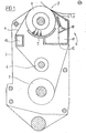
- the rubber cylinder of an offset printing machine is indicated at 1, of a type known per se, to which a washing device, designated as a whole by 2, is assigned.
- This has a frame which is delimited by lateral end shields 3 and is pivotably suspended in the printing press frame.
- the washing device 2 works with a washing cloth 4, which can be gradually wound up from a storage drum 5 and onto a take-up drum 6.
- the washing cloth 4 is guided via a blanket cylinder 1 opposite, here made as a brush roller platen roller 7, the can be adjusted to the rubber cylinder 1 by pivoting the frame delimited by the end shields 3.
- the brush roller 7 abuts a trough-shaped support plate 9 approximately diametrically opposite the contact zone 8.
- a nozzle bar 11 with spray nozzles 10 is provided, which is expediently arranged within the space delimited by the washing cloth 4 and is thus practically encapsulated by the washing cloth 4 itself, which provides excellent protection of the neighboring machine parts against moistening by the Spray nozzles 10 offers. At the same time, this ensures that the washcloth 4 can simply be inserted in the form of an envelope when changing the washcloth.
- guide cross members 12 and 13 are provided here, which can be connected to the side bearing plates 2 to form a stable frame.
- the guide crossbeam 12 also serves as a receptacle for the nozzle baffle 11 and as a receptacle for washing liquid which may drip off.
- the nozzle bar 11 is provided with a supply connection 14 which, as in the exemplary embodiment shown, can be branched over its entire width to ensure uniform application of the nozzle bar.
- a compressed air line 15 connected to a compressed air source and at least one, in the exemplary embodiment shown, two liquid lines which can be acted upon by an associated pump 16 each open into the supply connection 14 17 a.
- Each strand 17 is assigned to a specific washing liquid component. For example, the strand of water shown on the right in FIG. 2 and the strand shown on the left should carry an additive for detergent.
- the pumps 16 are expediently designed as piston pumps in order to achieve precise meterability of the washing liquid supplied to the nozzle bar 11.
- these are so-called suction and pressure pumps, each of which is connected to the assigned water tank 19 or the assigned detergent additive tank 20 with a suitable suction line 18.
- the check valves of the pumps are indicated at 21.
- the compressed air line 15 is here simply connected to a compressed air network indicated by the ring line 22. In the area of their connection to the supply nozzle 14, the compressed air line 15 and the liquid lines 17 are each secured by a check valve 23, so that any contamination is avoided.
- the supply nozzle 14 and the nozzle bar 11 provided therewith have a certain capacity for washing liquid, for example in the form of the collecting space 24 indicated here in dashed lines, to which all the spray nozzles are connected.
- a predetermined amount of liquid is now introduced into the nozzle bar 11 as a function of the gradual further transport of the washcloth 4 by corresponding actuation of the pumps 16.
- the pumps 16 are each to perform one stroke for this purpose.
- the stroke size of the pumps 16 is expediently adjustable, which is a precise adjustment of the pump stroke to the respective fluid requirements. So that no liquid can escape through the spray nozzles 10 when the nozzle bar 11 is acted upon, the maximum joint stroke volume of all pumps 16 should be less than the capacity of the nozzle bar 11 and of the supply nozzle 14 reaching as far as the check valves.
- the compressed air line 15 is now activated and the reservoir formed by the capacity of the nozzle bar and the supply connection connected therewith is emptied by the inflowing compressed air.
- a valve 25 is provided in the compressed air line 15, which is controlled by means of a control device (not shown here) in such a way that the compressed air line 15 is activated as soon as the pumps 16 have ended their stroke.
- the pumps 16 are pneumatically actuated, control slides 27 being provided in the drive line 26 leading to the ring line 22, which are controlled via the control device (not shown here) in such a way that the pumps 16 and thus the liquid strands 17 run counter to the compressed air line 15 activated or passivated.
- One spray cycle of the type described above is normally sufficient per wash cloth step. If more washing liquid is required, two or more spray cycles can also be provided per step.
- the nozzle bar 11 can only be pressurized with compressed air.
- the pumps 16 are simply shut down and the valve 25 is held in the open position by a suitable control pulse.
Abstract
Description
Die Erfindung betrifft eine Gummituchwaschvorrichtung mit einem an das Gummituch anstellbaren, schrittweise beförderbaren Waschtuch, das mittels eines durch mindestens eine Pumpe mit Waschflüssigkeit beaufschlagbaren Düsenbalkens befeuchtbar ist.The invention relates to a rubber blanket washing device with a wash cloth that can be placed on the rubber blanket and can be conveyed step by step, and which can be moistened by means of a nozzle bar which can be supplied with washing liquid by at least one pump.
Bei bekannten Anordnungen dieser Art wir.d der Düsenbalken durch eine Hochdruckpumpe derart mit Waschflüssigkeit versorgt, daß diese stets an den Sprühdüsen ansteht und beim Betrieb der Pumpe über diese abströmt. Hierbei ist daher im Düsenbalken stets eine seinem Fassungsvermögen entsprechende Flüssigkeitsmenge vorhanden, die bei jedem Ausbau des Düsenbalkens vorher entfernt werden muß, was diesen Arbeitsvorgang äußerst umständlich macht und zudem einen Verlust an Waschflüssigkeit bedeutet. Außerdem besteht hierbei die Gefahr, daß im Falle eines Schwnkens bzw. einer Schrägstellung des Düsenbalkens die noch vorhandene Restflüssigkeit ausläuft und umliegende Maschinenteile bzw. eine benachbarte Druckplatte beschädigt. Außerdem ist bei Anordnungen dieser Art eine genaue Dosierung der von den Sprühdüsen abgegebenen Flüssigkeitsmenge praktisch nicht zu bewerkstelligen.In known arrangements of this type, the nozzle bar is supplied with washing liquid by a high-pressure pump in such a way that it is always present at the spray nozzles and flows out through the pump during operation. Here, therefore, there is always an amount of liquid corresponding to its capacity in the nozzle bar, which must be removed each time the nozzle bar is removed, which makes this process extremely cumbersome and also means loss of washing liquid tet. In addition, there is a risk that in the event of a pivoting or inclined position of the nozzle bar, the remaining liquid that is still running out will leak and damage surrounding machine parts or an adjacent pressure plate. In addition, an exact dosage of the amount of liquid dispensed by the spray nozzles is practically impossible to achieve in arrangements of this type.
Hiervon ausgehend ist es daher die Aufgabe der vorliegenden Erfindung unter Vermeidung der Nachteile der bekannten Anordnungen eine Waschvorrichtung eingangs erwähnter Art zu schaffen, bei welcher der Düsenbalken bei jedem Sprühvorgang automatisch entleert wird und die dennoch einen höchst einfachen Aufbau aufweist und eine Umrüstung bereits bestehender Anordnungen zuläßt.Proceeding from this, it is therefore the object of the present invention to avoid the disadvantages of the known arrangements to create a washing device of the type mentioned above, in which the nozzle bar is automatically emptied during each spraying process and which nevertheless has a very simple structure and permits retrofitting of existing arrangements .
Die Lösung dieser Aufgabe gelingt gemäß der Erfindung in überraschend-einfacher Weise dadurch, daß während jedes Arbeitstakts mindestens einmal eine genau vorgebbare Waschflüssigkeitsdosis in den Düsenbalken einführbar ist und daß der Düsenbalken im Anschluß an eine derartige Beaufschlagung zum Ausblasen der aufgenommenen Waschflüssigkeitsdosis an eine Druckluftquelle anschließbar ist.This object is achieved in a surprisingly simple manner according to the invention in that a precisely predeterminable dose of washing liquid can be introduced into the nozzle bar at least once during each work cycle and that the nozzle bar can be connected to a compressed air source for blowing out the received washing liquid dose after such an exposure .
Diese Maßnahmen machen unter Beibehaltung des prinzipiellen Aufbaus in vorteilhafter Weise vom ohnehin vorhandenen Flüssigkeits-Fassungsvermögen eines Düsenbalkens Gebrauch, so daß eine nachträgliche Umrüstung bereits bestehender Anordnungen mit verhältnismäßig geringem Aufwand zu bewerkstelligen ist. Da der Düsenbalken bei jedem Arbeitstakt praktisch vollständig entleert wird, besteht keine Gefahr durch auslaufende Waschflüüsigkeit, die unter Umständen sehr aggressiv sein kann. Der Ausbau des Düsenbalkens - ein Vorgang, der bei jedem Plattenwechsel anfällt - gestaltet sich daher sehr einfach. Die hier zur Anwendung kommende Luft ergibt eine ausgezeichnete Vernebelung der Waschflüssigkeit und bewerkstelligt daher eine höchst gleichmäßige Flüssigkeitsverteilung. Außerdem ergeben sich hierbei relativ hohe Austrittsgeschwindigkeiten, so daß die Sprühdüsen einer stetigen Selbstreinigung unterliegen. Ein weiterer Vorteil dieser Maßnahmen ist darin zu sehen, daß es hier ohne weiteres möglich ist, das Waschtuch zur Bewerkstelligung einer bestimmten Trocknung ausschließlich mit Luft zu beaufschlagen. Hierzu ist die Flüssigkeitsversorgung einfach abzustellen und die Luftversorgung im Dauerbetrieb zu öffnen.These measures make use of the already existing liquid capacity of a nozzle bar while maintaining the basic structure, so that subsequent retrofitting of existing arrangements can be accomplished with relatively little effort. Because the nozzle bar is practically complete with every work cycle is emptied, there is no danger of leaking washing liquid, which can be very aggressive under certain circumstances. The removal of the nozzle bar - a process that occurs every time a plate is changed - is therefore very easy. The air used here results in an excellent atomization of the washing liquid and therefore achieves a highly uniform liquid distribution. In addition, there are relatively high outlet speeds, so that the spray nozzles are subject to constant self-cleaning. Another advantage of these measures can be seen in the fact that it is easily possible here to apply only air to the washcloth in order to achieve a certain drying. For this purpose, the liquid supply is simply switched off and the air supply is opened in continuous operation.
In der Praxis ist es vielfach erwünscht, eine aus mehreren, teilweise sehr aggressiven Komponenten zusammengesetzte Waschflüssigkeit zu verwenden. Dies ist bei einer Anordnung erfindungsgemäßer Art auf einfache Weise dadurch zu realisieren, daß für jede Komponente eine Pumpe vorgesehen ist, die über jeweils eine durch ein Rückschlagventil gesicherte Flüssigkeitsleitung vorzugsweise mit einem gemeinsamen Versorgungsstutzen des Düsenbalkens verbunden ist, an den gleichzeitig eine über ein Rückschlagventil gesicherte Druckluftleitung angeschlossen istl Innerhalb der unter Umständen sehr lamgen Flüssigkeitsleitung findet dabei in vorteilhafter Weise noch keine Vermischung statt.In practice, it is often desirable to use a washing liquid composed of several, sometimes very aggressive, components. In an arrangement according to the invention, this can be achieved in a simple manner in that a pump is provided for each component, which is preferably connected via a liquid line secured by a non-return valve to a common supply nozzle of the nozzle bar, to which is simultaneously secured by a non-return valve compressed air line ISTL connected within the sometimes very lam g s liquid line while no mixing takes place in an advantageous manner.
Eine weitere vorteilhafte Maßnahme kann darin bestehen, daß die Waschflüssigkeitspumpe bzw. -pumpen jeweils als Kolbenpumpe mit einstellbarem Hub ausgebildet ist. Hiermit läßt sich ein genau definiertes Fördervolumen bei dennoch gewährleisteter Anpassungsmöglichkeit an den Beddrf erreichenAnother advantageous measure can be the best hen that the washing liquid pump or pumps is designed as a piston pump with an adjustable stroke. This enables a precisely defined funding volume to be achieved with an adaptation to the Beddrf that is still guaranteed
Weitere Merkmale und Vorteile der Erfindung ergeben sich aus der nachstehenden Beschreibung eines besonders bevorzugten Ausführungsbeispiels anhand der Zeichnung in Verbindung mit den restlichen Unteransprüchen.Further features and advantages of the invention result from the following description of a particularly preferred exemplary embodiment with reference to the drawing in conjunction with the remaining subclaims.
Hierbei zeigen:
Figur 1 eine Gesamtansicht einer Gummituchwaschvorrichtung teilweise im Schnitt undFigur 2 ein Blockschaltbild eines besonders bevorzugten Ausführungsbeispiels der Erfindung für eine mit einer Zweikomponenten-Waschflüssigkeit arbeitende Anordnung.
- Figure 1 is an overall view of a blanket washing device partially in section and
- Figure 2 is a block diagram of a particularly preferred embodiment of the invention for an arrangement working with a two-component washing liquid.
In Figur 1 ist bei 1 der Gummizylinder einer Offset-Druckmaschine an sich bekannter Bauart angedeutet, dem eine als Ganzes mit 2 bezeichnete Waschvorrichtung zugeordnet ist. Diese weist einen durch seitliche Lagerschilde 3 begrenzten, schwenkbar im Druckmaschinengestell aufgehängten Rahmen auf. Die Waschvorrichtung 2 arbeitet mit einem Waschtuch 4, das schrittweise von einer Speichertrommel 5 ab und auf eine Aufnahmetrommel 6 aufwickelbar ist. Auf dem Weg zwischen Speichertrom- mel 5 und Aufnahmetrommel 6 ist das Waschtuch 4 über eine dem Gummizylinder 1 gegenüberliegende, hier als Bürstenwalze ausgebildete Andrückwalze 7 geführt, die durch Verschwenken des durch die Lagerschilde 3 begrenzten Rahmens an den Gummizylinder 1 anstellbar ist. Etwa diametral gegenüber der Kontaktzone 8 liegt die Bürstenwalze 7 an einem wannenförmigen Stützblech 9 an.In FIG. 1, the rubber cylinder of an offset printing machine is indicated at 1, of a type known per se, to which a washing device, designated as a whole by 2, is assigned. This has a frame which is delimited by
Zur Beaufschlagung des Waschtuchs 4 mit Waschflüssigkeit ist ein mit Sprühdüsen 10 besetzter Düsenbalken 11 vorgesehen, der zweckmäßig innerhalb des vom Waschtuch 4 begrenzten Raums angeordnet ist und somit praktisch durch das Waschtuch 4 selbst gekapselt wird, was einen ausgezeichneten Schutz der benachbarten Maschinenteile gegen Befeuchtung durch die Sprühdüsen 10 bietet. Gleichzeitig ist hierdurch gewährleistet, daß das Waschtuch 4 bei einem Waschtuchwechsel einfach in Form einer Einhüllenden eingelegt werden kann. Zur zusätzlichen Führung des Waschtuchs 4 sind hier Leittraversen 12 bzw. 13 vorgesehen, die zur Bildung eines stabilen Rahmens mit den seitlichen Lagerschilden 2 verbunden sein können. Die Leittraverse 12 dient gleichzeitig als Aufnahme für den Düsenbakken 11 und als Aufnahmewanne für evtl. abtropfende Waschflüssigkeit.To apply the
Der Düsenbalken 11 ist, wie am besten aus Figur 2 erkennbar ist, mit einem Versorgungsstutzen 14 versehen, der, wie im dargestellten Ausführungsbeispiel, zur Gewährleistung einer gleichmäßigen Beaufschla-, gung des Düsenbalkens über seiner gesamten Breite verzweigt sein kann. In den Versorgungsstutzen 14 münden eine an eine Druckluftquelle angeschlossene Druckluftleitung 15 sowie mindestens eine, im dargestellten Ausführungsbeispiel zwei über jeweils eine zugeordnete Pumpe 16 beaufschlagbare Flüssigkeitsstränge 17 ein. Jeder Strang 17 ist dabei einer bestimmten Waschflüssigkeitskomponente zugeordnet. So soll etwa der in Figur 2 rechts gezeichnete Strang Wasser und der links gezeichnete Strang einen Waschmittelzusatz führen. Zur Bewerkstelligung einer genauen Dosierbarkeit der dem Düsenbalken 11 jeweils zugeführten Waschflüssigkeit sind die Pumpen 16 zweckmäßig als Kolbenpumpen ausgebildet. Im dargestellten Ausführungsbeispiel handelt es sich dabei um sogenannte Saug- und Druckpumpen, die mit jeweils einer geeigneten Saugleitung 18 mit dem zugeordneten Wassertank 19 bzw. dem zugeordneten Waschmittelzusatztank 20 verbunden sind. Bei 21 sind die Rückschlagklappen der Pumpen angedeutet. Die Druckluftleitung 15 ist hier einfach mit einem durch die Ringleitung 22 angedeuteten Druckluftnetz verbunden. Im Bereich ihres Anschlusses an den Versorgungsstutzen 14 sind die Druckluftleitung 15 sowie die Flüssigkeitsstränge 17 jeweils durch ein Rückschlagventil 23 gesichert, so daß jede Verunreinigung unterbleibt.As can best be seen from FIG. 2, the
Der Versorgungsstutzen 14 und der hiermit versehene Düsenbalken 11 besitzen ein bestimmtes Fassungsvermögen für Waschflüssigkeit, etwa in Form des hier gestrichelt angedeuteten Sammelraums 24, an den sämtliche Sprühdüsen angeschlossen sind. Während des Betriebs wird nun in Abhängigkeit von dem schrittweisen Weitertransport des Waschtuchs 4 durch entsprechende Betätigung der Pumpen 16 eine vorbestimmte Flüssigkeitsmenge in den Düsenbalken 11 eingebracht. Im dargestellten Ausführungsbeispiel sollen die Pumpen 16 hierzu jeweils einen Hub ausführen. Zweckmäßig ist die Hubgröße der Pumpen 16 verstellbar, was eine genaue Anpassung des Pumpenhubsan den jeweiligen Flüssigkeitsbedarf ermöglicht. Damit bei dieser Beaufschlagung des Düsenbalkens 11 noch keine Flüssigkeit über die Sprühdüsen 10 entweichen kann, soll das gemeinsame maximale Hubvolumen sämtlicher Pumpen 16 unter dem Fassungsvermögen des Düsenbalkens 11 sowie des bis zu den Rückschlagventilen reichenden Versorgungsstutzens 14 sein.The
Im Anschluß an diesen Füllvorgang wird nun die Druckluftleitung 15 aktiviert und damit das durch das Fassungsvermögen von Düsenbalken und hiermit verbundenem Versorgungsstutzen gebildete Reservoir durch die einströmende Druckluft entleert. Hierzu ist in der Druckluftleitung 15 ein Ventil 25 vorgesehen, das mittels einer hier nicht näher dargestellten Steuereinrichtung so angesteuert ist, daß die Druckluftleitung 15 aktiviert wird, sobald die Pumpen 16 ihren Hub beendet haben. Im dargestellten Ausführungsbeispiel sind die Pumpen 16 pneumatisch betätigt, wobei jeweils in der zur Ringleitung 22 führenden Antriebsleitung 26 Steuerschieber 27 vorgesehen sind, die über die hier nicht näher dargestellte Steuereinrichtung so angesteuert sind, daß die Pumpen 16 und damit die Flüssigkeitsstränge 17 gegenläufig zur Druckluftleitung 15 aktiviert bzw. passiviert werden.Following this filling process, the
Normalerweise reicht pro Waschtuchschritt ein Sprühtakt vorstehend beschriebener Art aus. Bei größerem Bedarf an Waschflüssigkeit können aber pro Schritt auch zwei oder mehrere Sprühtakte vorgesehen sein.One spray cycle of the type described above is normally sufficient per wash cloth step. If more washing liquid is required, two or more spray cycles can also be provided per step.
Zur Bewerkstelligung eines Trocknungsvorgangs kann der Düsenbalken 11 ausschließlich mit Druckluft beaufschlagt werden. Die Pumpen 16 sind dabei einfach stillgelegt und das Ventil 25 ist durch einen geeigneten Steuerimpuls in Öffnungsstellung gehalten.To accomplish a drying process, the
Claims (6)
Priority Applications (1)
| Application Number | Priority Date | Filing Date | Title |
|---|---|---|---|
| EP79103639A EP0025806B1 (en) | 1979-09-25 | 1979-09-25 | Device for cleaning a blanket |
Applications Claiming Priority (1)
| Application Number | Priority Date | Filing Date | Title |
|---|---|---|---|
| EP79103639A EP0025806B1 (en) | 1979-09-25 | 1979-09-25 | Device for cleaning a blanket |
Publications (2)
| Publication Number | Publication Date |
|---|---|
| EP0025806A1 true EP0025806A1 (en) | 1981-04-01 |
| EP0025806B1 EP0025806B1 (en) | 1983-05-25 |
Family
ID=8186200
Family Applications (1)
| Application Number | Title | Priority Date | Filing Date |
|---|---|---|---|
| EP79103639A Expired EP0025806B1 (en) | 1979-09-25 | 1979-09-25 | Device for cleaning a blanket |
Country Status (1)
| Country | Link |
|---|---|
| EP (1) | EP0025806B1 (en) |
Cited By (5)
| Publication number | Priority date | Publication date | Assignee | Title |
|---|---|---|---|---|
| AU614794B2 (en) * | 1988-09-13 | 1991-09-12 | Nikka Kabushiki Kaisha | Cleaning apparatus and method of cleaning a blanket cylinder of a printing press |
| WO1995007182A1 (en) * | 1993-09-08 | 1995-03-16 | Jimek International Ab | A spray tube for a blanket washing device at a printing press |
| EP0572391B1 (en) * | 1990-03-06 | 1995-10-18 | BERNTSSON, Reinhold | System at spray dampening apparatus |
| DE10030027A1 (en) * | 2000-06-17 | 2001-12-20 | Baldwin Grafotec Gmbh | Washing device for printing machine cylinder; has fluid output beam to deliver washing fluid to washing towel pressed against cylinder and dispensing unit to supply determined quantity of fluid |
| EP1642717A1 (en) * | 2004-10-01 | 2006-04-05 | Technotrans AG | Device for cleaning surfaces of cylinders in a printing machine |
Families Citing this family (4)
| Publication number | Priority date | Publication date | Assignee | Title |
|---|---|---|---|---|
| DE102004011860A1 (en) * | 2004-03-11 | 2005-09-29 | Koenig & Bauer Ag | Broad spray head for printing machine cylinder or roller cleaning system covers entire width of cylinder and has mixer at center point creating homogenous mix of cleaning fluid and air |
| DE102004011861A1 (en) * | 2004-03-11 | 2005-09-29 | Koenig & Bauer Ag | Cylinder or roller cleaning system for use in printing machine has broad spray head covering entire width of cylinder and has mixer creating homogenous mix of cleaning fluid and air |
| DE102004011859A1 (en) * | 2004-03-11 | 2005-09-29 | Koenig & Bauer Ag | De-aerating system for rotary printer cylinder or roller spray cleaner has fluid sensor, air bleed line, control valve and low-pressure reservoir and return system for fluid carried over with bleed air |
| DE102004018735A1 (en) * | 2004-04-17 | 2005-11-17 | Baldwin Germany Gmbh | The fluid sprayer device |
Citations (2)
| Publication number | Priority date | Publication date | Assignee | Title |
|---|---|---|---|---|
| US3508711A (en) * | 1967-12-29 | 1970-04-28 | Ryco Graphic Mfg | Fluid dispensing system |
| FR2260394A1 (en) * | 1974-02-11 | 1975-09-05 | Baldwin Gegenheimer Corp |
-
1979
- 1979-09-25 EP EP79103639A patent/EP0025806B1/en not_active Expired
Patent Citations (2)
| Publication number | Priority date | Publication date | Assignee | Title |
|---|---|---|---|---|
| US3508711A (en) * | 1967-12-29 | 1970-04-28 | Ryco Graphic Mfg | Fluid dispensing system |
| FR2260394A1 (en) * | 1974-02-11 | 1975-09-05 | Baldwin Gegenheimer Corp |
Cited By (6)
| Publication number | Priority date | Publication date | Assignee | Title |
|---|---|---|---|---|
| AU614794B2 (en) * | 1988-09-13 | 1991-09-12 | Nikka Kabushiki Kaisha | Cleaning apparatus and method of cleaning a blanket cylinder of a printing press |
| EP0572391B1 (en) * | 1990-03-06 | 1995-10-18 | BERNTSSON, Reinhold | System at spray dampening apparatus |
| WO1995007182A1 (en) * | 1993-09-08 | 1995-03-16 | Jimek International Ab | A spray tube for a blanket washing device at a printing press |
| DE10030027A1 (en) * | 2000-06-17 | 2001-12-20 | Baldwin Grafotec Gmbh | Washing device for printing machine cylinder; has fluid output beam to deliver washing fluid to washing towel pressed against cylinder and dispensing unit to supply determined quantity of fluid |
| DE10030027B4 (en) * | 2000-06-17 | 2008-12-11 | Baldwin Germany Gmbh | Washing device for printing press cylinder |
| EP1642717A1 (en) * | 2004-10-01 | 2006-04-05 | Technotrans AG | Device for cleaning surfaces of cylinders in a printing machine |
Also Published As
| Publication number | Publication date |
|---|---|
| EP0025806B1 (en) | 1983-05-25 |
Similar Documents
| Publication | Publication Date | Title |
|---|---|---|
| DE2826135C2 (en) | Blanket washing device | |
| DE3034804C2 (en) | Device for applying a medium to a screen stencil, in particular for printing or dyeing | |
| AT393246B (en) | APPLICATION DEVICE FOR APPLYING FLOWABLE MEDIA ON LEVEL SURFACES, RAILS, ROLLERS OD. DGL. | |
| DE2300289C2 (en) | Device for applying liquid or pasty paint for screen printing machines | |
| EP0082465A1 (en) | Apparatus for feeding foam to a coating device | |
| EP0310826B1 (en) | Apparatus for delivering liquid to a vat | |
| DE2739556A1 (en) | DEVICE FOR THE CONTINUOUS CLEANING OF A WIPING CYLINDER IN A STEEL STRAIGHT PRINTING MACHINE | |
| EP0025806B1 (en) | Device for cleaning a blanket | |
| DE3509730C2 (en) | ||
| DE19705006C2 (en) | Device for supplying and extracting ink in printing machines | |
| DE3128928A1 (en) | DEVICE FOR CLEANING INKING ROLLERS OF A ROLLER INKING MACHINE FOR PRINTING MACHINES | |
| EP0570727B1 (en) | Washing device for printing machines | |
| EP1621257B1 (en) | Device for applying sections of a liquid onto a running web | |
| DE2415148A1 (en) | DEVICE FOR PRINTING, COATING OR COLORING TRACKS | |
| EP0570763B1 (en) | Washing device for printing machine | |
| DE2804801A1 (en) | Rubber cloth washing equipment for printing press - has washing fluid delivered to porous sintered strip bearing against cloth | |
| DE4208079C2 (en) | Device for washing a cylinder of a printing press | |
| DE3736397A1 (en) | Blanket washing device | |
| WO1981000828A1 (en) | Device for washing of blanket | |
| DE2458234C3 (en) | Method for cleaning a paint nozzle of a device for spray-printing a porous material and device for carrying out the method | |
| DE3802256C2 (en) | ||
| EP0730527B1 (en) | Device for supplying printing ink to the inking system of a printer | |
| DE3536094A1 (en) | DEVICE FOR APPLYING LIQUIDS TO MOVING TEXTILE MATERIAL OR THE LIKE | |
| DE102005003030A1 (en) | Printing machine moistening device and printing machine washing device | |
| EP1586450A1 (en) | Fluid product spraying device |
Legal Events
| Date | Code | Title | Description |
|---|---|---|---|
| PUAI | Public reference made under article 153(3) epc to a published international application that has entered the european phase |
Free format text: ORIGINAL CODE: 0009012 |
|
| AK | Designated contracting states |
Designated state(s): CH FR GB IT SE |
|
| 17P | Request for examination filed |
Effective date: 19810921 |
|
| ITF | It: translation for a ep patent filed |
Owner name: STUDIO JAUMANN |
|
| GRAA | (expected) grant |
Free format text: ORIGINAL CODE: 0009210 |
|
| AK | Designated contracting states |
Designated state(s): CH FR GB IT SE |
|
| ET | Fr: translation filed | ||
| PLBE | No opposition filed within time limit |
Free format text: ORIGINAL CODE: 0009261 |
|
| STAA | Information on the status of an ep patent application or granted ep patent |
Free format text: STATUS: NO OPPOSITION FILED WITHIN TIME LIMIT |
|
| 26N | No opposition filed | ||
| ITTA | It: last paid annual fee | ||
| PGFP | Annual fee paid to national office [announced via postgrant information from national office to epo] |
Ref country code: CH Payment date: 19941223 Year of fee payment: 16 |
|
| EAL | Se: european patent in force in sweden |
Ref document number: 79103639.5 |
|
| PG25 | Lapsed in a contracting state [announced via postgrant information from national office to epo] |
Ref country code: CH Effective date: 19950930 |
|
| REG | Reference to a national code |
Ref country code: CH Ref legal event code: PL |
|
| PGFP | Annual fee paid to national office [announced via postgrant information from national office to epo] |
Ref country code: GB Payment date: 19980907 Year of fee payment: 20 |
|
| PGFP | Annual fee paid to national office [announced via postgrant information from national office to epo] |
Ref country code: FR Payment date: 19980917 Year of fee payment: 20 |
|
| PGFP | Annual fee paid to national office [announced via postgrant information from national office to epo] |
Ref country code: SE Payment date: 19980922 Year of fee payment: 20 |
|
| PG25 | Lapsed in a contracting state [announced via postgrant information from national office to epo] |
Ref country code: GB Free format text: LAPSE BECAUSE OF EXPIRATION OF PROTECTION Effective date: 19990924 |
|
| PG25 | Lapsed in a contracting state [announced via postgrant information from national office to epo] |
Ref country code: SE Free format text: LAPSE BECAUSE OF NON-PAYMENT OF DUE FEES Effective date: 19990926 |
|
| REG | Reference to a national code |
Ref country code: GB Ref legal event code: PE20 Effective date: 19990924 |
|
| EUG | Se: european patent has lapsed |
Ref document number: 79103639.5 |
|
| EUG | Se: european patent has lapsed |
Ref document number: 79103639.5 |