EP0572355B1 - Module mettant en oeuvre la pervaporation de fluides - Google Patents
Module mettant en oeuvre la pervaporation de fluides Download PDFInfo
- Publication number
- EP0572355B1 EP0572355B1 EP93810375A EP93810375A EP0572355B1 EP 0572355 B1 EP0572355 B1 EP 0572355B1 EP 93810375 A EP93810375 A EP 93810375A EP 93810375 A EP93810375 A EP 93810375A EP 0572355 B1 EP0572355 B1 EP 0572355B1
- Authority
- EP
- European Patent Office
- Prior art keywords
- heating
- pervaporization
- module according
- chambers
- magazines
- Prior art date
- Legal status (The legal status is an assumption and is not a legal conclusion. Google has not performed a legal analysis and makes no representation as to the accuracy of the status listed.)
- Expired - Lifetime
Links
- 239000012530 fluid Substances 0.000 title claims description 11
- 238000005373 pervaporation Methods 0.000 title abstract description 29
- 238000010438 heat treatment Methods 0.000 claims abstract description 34
- 239000012465 retentate Substances 0.000 claims abstract description 12
- 239000012528 membrane Substances 0.000 claims description 8
- 239000012466 permeate Substances 0.000 claims description 8
- 239000002184 metal Substances 0.000 claims description 5
- 229910052751 metal Inorganic materials 0.000 claims description 5
- 230000014759 maintenance of location Effects 0.000 claims 6
- 241000282472 Canis lupus familiaris Species 0.000 claims 1
- 239000000463 material Substances 0.000 claims 1
- 230000003014 reinforcing effect Effects 0.000 claims 1
- 238000007789 sealing Methods 0.000 claims 1
- 238000009826 distribution Methods 0.000 abstract description 6
- 239000007788 liquid Substances 0.000 description 7
- 238000010276 construction Methods 0.000 description 4
- 238000012423 maintenance Methods 0.000 description 3
- 238000013461 design Methods 0.000 description 2
- 238000009792 diffusion process Methods 0.000 description 2
- 238000001704 evaporation Methods 0.000 description 2
- 230000008020 evaporation Effects 0.000 description 2
- 238000004080 punching Methods 0.000 description 2
- 229910052770 Uranium Inorganic materials 0.000 description 1
- 239000000919 ceramic Substances 0.000 description 1
- 238000001311 chemical methods and process Methods 0.000 description 1
- 210000001520 comb Anatomy 0.000 description 1
- 238000003780 insertion Methods 0.000 description 1
- 230000037431 insertion Effects 0.000 description 1
- 238000009434 installation Methods 0.000 description 1
- 238000004519 manufacturing process Methods 0.000 description 1
- 239000007769 metal material Substances 0.000 description 1
- 239000000203 mixture Substances 0.000 description 1
- 238000012856 packing Methods 0.000 description 1
- 238000000926 separation method Methods 0.000 description 1
- 238000003860 storage Methods 0.000 description 1
- JFALSRSLKYAFGM-UHFFFAOYSA-N uranium(0) Chemical compound [U] JFALSRSLKYAFGM-UHFFFAOYSA-N 0.000 description 1
- 238000009834 vaporization Methods 0.000 description 1
- 230000008016 vaporization Effects 0.000 description 1
Images
Classifications
-
- B—PERFORMING OPERATIONS; TRANSPORTING
- B01—PHYSICAL OR CHEMICAL PROCESSES OR APPARATUS IN GENERAL
- B01D—SEPARATION
- B01D53/00—Separation of gases or vapours; Recovering vapours of volatile solvents from gases; Chemical or biological purification of waste gases, e.g. engine exhaust gases, smoke, fumes, flue gases, aerosols
- B01D53/22—Separation of gases or vapours; Recovering vapours of volatile solvents from gases; Chemical or biological purification of waste gases, e.g. engine exhaust gases, smoke, fumes, flue gases, aerosols by diffusion
-
- B—PERFORMING OPERATIONS; TRANSPORTING
- B01—PHYSICAL OR CHEMICAL PROCESSES OR APPARATUS IN GENERAL
- B01D—SEPARATION
- B01D61/00—Processes of separation using semi-permeable membranes, e.g. dialysis, osmosis or ultrafiltration; Apparatus, accessories or auxiliary operations specially adapted therefor
- B01D61/36—Pervaporation; Membrane distillation; Liquid permeation
- B01D61/362—Pervaporation
-
- B—PERFORMING OPERATIONS; TRANSPORTING
- B01—PHYSICAL OR CHEMICAL PROCESSES OR APPARATUS IN GENERAL
- B01D—SEPARATION
- B01D2313/00—Details relating to membrane modules or apparatus
- B01D2313/22—Cooling or heating elements
Definitions
- Pervaporation is a membrane separation process by means of which one or more portions of a fluid mixture are separated by means of permeation.
- One component diffuses through the permselective membrane, one side of which the liquid flows over, preferably in comparison to the other components.
- the liquid diffused through is the permeate, while the remaining liquid is called retentate.
- a vacuum is usually applied to the permeate side of the membrane, which leads to evaporation of the permeate.
- the pervaporation is improved by the addition of heat because this accelerates the diffusion process, because it also facilitates the evaporation of the permeate in the pervaporation chamber and because the heat loss is finally compensated for by the enthalpy of vaporization.
- the homogeneity of the temperature distribution is extremely important.
- a module for performing the pervaporation of fluids according to the preamble of the claim is known.
- This module is particularly suitable for the enrichment of uranium with the isotope 235 by means of diffusion. Accordingly, the temperature control is of less importance here than, for example, in pervaporation in chemical process plants in which the purity of a fluid is to be increased. Consequently, the known module works without heating chambers.
- a module which additionally has a heating chamber is known from JP-A-63-59310.
- two flow spaces which are bounded on the one hand by two permeable membranes and on the other hand by a heating plate, are formed and the retentate side of the membrane is cooled.
- this does not allow a uniform temperature distribution in the liquid to be pervaporated.
- such a construction results in an unfavorable ratio of the size to the amount of liquid to be passed through.
- EP-A-0'118'760 and US-A-3'695'444 also disclose modules which have a sandwich-like structure of mutually adjacent, mutually delimiting heating chambers, pervaporation chambers and retentate chambers. Such modules can be manufactured very compactly, but are only suitable for small flow rates and due to the meandering flow paths through a series of chambers with a high flow resistance afflicted.
- the module according to EP-A-0'164'326 has the same structure. The only difference here is that the adjacent chambers are not successively next to each other in the form of plates, but are nested concentrically one inside the other.
- the object of the present invention is therefore to improve a module in accordance with the preamble of the claim so that a high liquid throughput in relation to the volume of the module with an optimal temperature distribution is made possible.
- Claim 2 describes a particularly advantageous embodiment, which is inexpensive to manufacture and optimal in terms of assembly and maintenance, because the heating cassettes on one side and the pervaporation cassettes on the other side, which are comb-like are in the flow container to one another, are accessible and can therefore be replaced.
- the embodiment according to claim 4 guarantees the deformation-free course of all walls of the flow container, whereby exact flow conditions are only ensured.
- the same is achieved by the special design of the pervaporation cassettes and heating cassettes according to claims 5 and 6, respectively, since the corresponding grate deformations can be absorbed by excess pressure or negative pressure in the corresponding cassettes.
- the installation of several inlet and outlet connections on the heating and pervaporation cassettes also leads to an improvement in the flow and temperature control conditions.
- the design of the module according to the invention is not limited to cubic shapes of the flow-through container, which shows the solution according to claim 9.
- the module according to the invention for carrying out the pervaporation of fluids has three essential components, namely a flow container 1 in which one or more pervaporation cassette 2 or cassette and several heating cassette 3 are arranged.
- a pervaporation cassette 2 which is mounted between two heating cassettes 3, is provided in the flow container 1.
- the flow container has the shape of a flat, cuboid Box and the various cassettes 2, 3 have the shape of plates, the plates of each cassette forming a chamber.
- Such an embodiment is shown in detail in the drawing.
- the flow container could also have the shape of a cylinder.
- the plate-shaped pervaporation and heating cassettes can then be arranged alternately and radially in a star shape next to one another.
- the cylinder wall of the flow container can then serve as a carrier for the other cassettes.
- Such an embodiment will not be discussed further below because the shape, in particular of the cassettes and their relative arrangement to one another, remains unaffected.
- the cassettes only had to increase in thickness from the cylinder axis to the cylinder wall, so that the gaps between the cassettes are the same everywhere and the fluid flows uniformly everywhere.
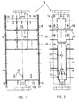
- the flow container is designed in the form of a cubic box. This has a feed inlet 10 and a retentate outlet 11 on. Feed inlet and retentate outlet are arranged opposite one another on the two short end faces of the box-shaped flow container 1.
- the fluid to be pervaporated flows continuously through the container from the feed inlet to the retentate outlet.
- the two short end walls 12 are firmly connected, in particular welded, to the two front walls 13 on the front and rear of the container.
- the edges of the front walls 13 are each bent at right angles to a circumferential flange 14 in the area of their lateral limitation. These two flanges 14 form the contact surfaces for the long, lateral longitudinal end walls 15.
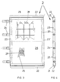
- the aforementioned pervaporation cassette 2 is shown in detail in FIGS. 3 and 4.
- the pervaporation cassette 2 comprises a frame construction 20, the upper and lower strips 21 of which are each provided with a holding comb 22. These holding combs 22 are dimensioned such that they can be inserted into the incisions 18 'in the supports 18 in the flow container 1.
- One longitudinal bar 23 is provided with inlet connection 24, while the opposite longitudinal bar 23 'is completely closed.
- Carrier plates 25 are arranged within the frame construction, sealingly connected to the strips 22, 23 and 23 ', and are covered with a permselective membrane 26 on the retentate side. This membrane is partially broken through in FIG. 3, so that you can see the perforations 27 in the support plates 25.
- carrier surfaces can be used which consist either of expanded metal, metal mesh or sintered synthetic, ceramic or metallic material with sufficient porosity.
- a pressure-absorbing grid 28 is inserted between the two support surfaces 25, support plates perforated in FIG. 3. This is essential in order to keep the gap width between one heating cassette and the adjacent pervaporation cassette as constant as possible, so that the flow conditions of the retentate in the gap are as constant as possible.
- the permeate or the permeate vapor is drawn off via the outlet connection 24. The permeate is only condensed outside the module according to the invention.
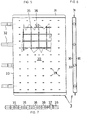
- a heating cassette of the module according to the invention is shown in detail in FIGS. 5-7. It consists of two metal sheets which are directly connected to one another at the longitudinal edges and which are likewise shaped and welded to a holding comb 31 at the upper and lower edges, which can be inserted into the incisions 18 ′ of the comb-like supports 18.
- inlet and outlet connections 32 are provided, which serve to guide the heating medium.
- the absolutely flat course of the sheets 30 is extremely important, in order in turn to keep the gap width to the adjacent pervaporation cassette the same. Therefore, there is a tensile force in the heating cassette 3 receiving, grid-shaped grate 34. This consists of crosswise laid longitudinal and transverse webs 36.
- the webs are provided with flow openings 37.
- the transverse webs 36 additionally have cams 38 which are at least as high as the sheets 30 are thick.
- cams 38 which are at least as high as the sheets 30 are thick.
- punchings 39 are provided in the metal sheets, in which the cams fit in a form-fitting manner.
- the cams must be kept sealed in the punchings.
- This special construction of the individual cassettes enables a very narrow gap to be created between the adjacent cassettes. The gap between the two outermost heating cassettes and the front walls 13 of the flow container can go to zero. This eliminates the need for a special line for the fluid to be pervaporated. In this way, a relatively simple module with high efficiency and excellent maintenance properties is realized.
Landscapes
- Engineering & Computer Science (AREA)
- Chemical & Material Sciences (AREA)
- Water Supply & Treatment (AREA)
- Chemical Kinetics & Catalysis (AREA)
- Analytical Chemistry (AREA)
- General Chemical & Material Sciences (AREA)
- Oil, Petroleum & Natural Gas (AREA)
- Separation Using Semi-Permeable Membranes (AREA)
- External Artificial Organs (AREA)
- Preparation Of Compounds By Using Micro-Organisms (AREA)
- Pharmaceuticals Containing Other Organic And Inorganic Compounds (AREA)
- Medicines Containing Material From Animals Or Micro-Organisms (AREA)
Claims (9)
- Module pour la réalisation de la pervaporation de fluides, comportant une entrée d'alimentation (10) et une sortie pour le rétentat (11), ainsi qu'au moins une chambre de pervaporation en forme de plaques (2), qui est munie de chaque côté, en nappe, d'une membrane perméable (26) et d'au moins une sortie pour le perméat, tandis que chaque chambre de pervaporation (2) se situe entre deux chambres de chauffage (3) en forme de plaques qui sont directement voisines d'elle, caractérisé en ce que les chambres de pervaporation (2) et les chambres de chauffage (3) sont formées de cassettes autoportantes, fermées sur elles-mêmes, qui sont maintenues espacées, sans contact l'une avec l'autre, dans un récipient de passage continu fermé (1), de telle sorte que le fluide à faire pervaporer soit conduit autour de chaque cassette de pervaporation et entre celle-ci et la cassette de chauffage voisine dans un interstice en ligne droite de l'entrée d'alimentation (10) à la sortie de rétentat (11).
- Module selon la revendication 1, caractérisé en ce que le récipient de passage continu (1) a la forme d'une boîte étroite rectangulaire, l'entrée d'alimentation (10) et la sortie de rétentat (11) étant placées sur deux parois d'extrémité étroites (12) opposées l'une à l'autre, tandis que l'une des parois d'extrémité longitudinales (15) sert de support pour les cassettes de chauffage en forme de plaques (3) et la paroi d'extrémité longitudinale lui faisant face (15) sert de support pour les cassettes de pervaporation en forme de plaques (2), les deux parois d'extrémité longitudinales étant maintenues de façon étanche et amovible sur le récipient de passage continu (1).
- Module selon la revendication 1, caractérisé en ce que sont placés dans le récipient de passage continu (1) des supports en forme de dents (18), sur lesquels s'appuient aussi bien les cassettes de chauffage (3) que les cassettes de pervaporation (2).
- Module selon la revendication 2, caractérisé en ce que les deux surfaces frontales (13) du récipient de passage continu (1) sont munies de bagues de renforcement en forme de treillis (13') et d'une flasque (14) reposant perpendiculairement en périphérie, sur lesquelles les parois d'extrémité longitudinales (15) formant recouvrement peuvent être vissées (16).
- Module selon la revendication 2, caractérisé en ce que chaque cassette de pervaporation (2) consiste en deux surfaces supports (25) reliées entre elles, perforées (27), revêtues d'un matériau perméable (26), entre lesquelles est placée une grille absorbant l'effort de pression (28).
- Module selon la revendication 2, caractérisé en ce que chaque cassette de chauffage (3) consiste en deux tôles estampées reliées entre elles (30), entre lesquelles est disposée une grille perforée (35,36) absorbant l'effort de traction, avec des ergots (38) passant avec engagement positif dans les perforations (39) de la tôle (30).
- Module selon la revendication 2, caractérisé en ce que chaque cassette de pervaporation (2) présente plusieurs raccords de déversement (24) sur la même face d'extrémité longitudinale (23).
- Module selon la revendication 2, caractérisé en ce que chaque cassette de chauffage (3) présente plusieurs raccords d'admission et de déversement (32) sur la même face d'extrémité longitudinale (33).
- Module selon la revendication 2, caractérisé en ce que le récipient de passage continu (1) a la forme d'un cylindre, tandis que les cassettes de chauffage en forme de plaques (3) et les cassettes de pervaporation en forme de plaques (2) sont disposées en alternance et radialement les unes à côté des autres.
Applications Claiming Priority (2)
| Application Number | Priority Date | Filing Date | Title |
|---|---|---|---|
| CH1720/92 | 1992-05-27 | ||
| CH1720/92A CH685331A5 (de) | 1992-05-27 | 1992-05-27 | Modul zur Durchführung der Pervaporation von Fluiden. |
Publications (2)
| Publication Number | Publication Date |
|---|---|
| EP0572355A1 EP0572355A1 (fr) | 1993-12-01 |
| EP0572355B1 true EP0572355B1 (fr) | 1996-04-24 |
Family
ID=4217028
Family Applications (1)
| Application Number | Title | Priority Date | Filing Date |
|---|---|---|---|
| EP93810375A Expired - Lifetime EP0572355B1 (fr) | 1992-05-27 | 1993-05-21 | Module mettant en oeuvre la pervaporation de fluides |
Country Status (9)
| Country | Link |
|---|---|
| US (1) | US5389255A (fr) |
| EP (1) | EP0572355B1 (fr) |
| JP (1) | JPH0686917A (fr) |
| AT (1) | ATE137135T1 (fr) |
| CH (1) | CH685331A5 (fr) |
| DE (1) | DE59302324D1 (fr) |
| DK (1) | DK0572355T3 (fr) |
| ES (1) | ES2086916T3 (fr) |
| FI (1) | FI932016A7 (fr) |
Families Citing this family (8)
| Publication number | Priority date | Publication date | Assignee | Title |
|---|---|---|---|---|
| DE19910549A1 (de) * | 1999-03-10 | 2000-09-14 | Metallgesellschaft Ag | Verfahren und Vorrichtung zur Trennung von flüssigen und/oder dampfförmigen Stoffgemischen durch Pervaporation und/oder Dampfpemeation |
| DE19957641C1 (de) * | 1999-11-30 | 2001-06-13 | Membraflow Gmbh & Co Kg Filter | Filtermembranmodul mit integriertem Wärmetauscher |
| US6306307B1 (en) | 2000-03-07 | 2001-10-23 | Fielding Chemical Technologies, Inc. | Pervaporation apparatus and method |
| AU2004291500A1 (en) * | 2003-11-18 | 2005-06-02 | Exxonmobil Research And Engineering Company | Method and apparatus for separating aromatic hydrocarbons in a non-adiabatic membrane system |
| AU2004291499A1 (en) * | 2003-11-18 | 2005-06-02 | Exxonmobil Research And Engineering Company | Process and system for separating components for blending |
| US7318898B2 (en) * | 2003-11-18 | 2008-01-15 | Exxonmobil Research And Engineering Company | Polymeric membrane wafer assembly and method |
| US7303681B2 (en) * | 2003-11-18 | 2007-12-04 | Exxonmobil Research And Engineering Company | Dynamic membrane wafer assembly and method |
| JP5391307B2 (ja) | 2012-05-14 | 2014-01-15 | ファナック株式会社 | 射出成形機の安全扉装置 |
Family Cites Families (11)
| Publication number | Priority date | Publication date | Assignee | Title |
|---|---|---|---|---|
| NL257545A (fr) * | 1959-11-04 | |||
| US3398091A (en) * | 1966-08-09 | 1968-08-20 | Ionics | Membrane separation apparatus and process |
| US3520803A (en) * | 1968-12-24 | 1970-07-21 | Ionics | Membrane fluid separation apparatus and process |
| US3608610A (en) * | 1969-10-01 | 1971-09-28 | Ionics | Apparatus for evaporative separation of liquids through microporous panels |
| DE2911508A1 (de) * | 1978-03-28 | 1979-10-04 | Kuraray Co | Fluidbehandlungsvorrichtung |
| DE3304956A1 (de) * | 1983-02-12 | 1984-08-16 | Gkss - Forschungszentrum Geesthacht Gmbh, 2054 Geesthacht | Einrichtung zur trennung von loesungen durch pervaporation |
| SE452451B (sv) * | 1984-06-07 | 1987-11-30 | Svenska Utvecklings Ab | Anordning for membrandestillation |
| DE3441190A1 (de) * | 1984-11-10 | 1986-05-15 | Metallgesellschaft Ag, 6000 Frankfurt | Einrichtung zur trennung von fluessigkeitsgemischen durch pervaporation |
| JPS6359310A (ja) * | 1986-08-29 | 1988-03-15 | Nitto Electric Ind Co Ltd | サ−モパ−ベ−パレ−シヨン装置 |
| JPS6369506A (ja) * | 1986-09-12 | 1988-03-29 | Mitsui Eng & Shipbuild Co Ltd | 液体の分離方法 |
| JPS63151305A (ja) * | 1986-12-15 | 1988-06-23 | Mitsui Eng & Shipbuild Co Ltd | 浸透気化膜モジユ−ル |
-
1992
- 1992-05-27 CH CH1720/92A patent/CH685331A5/de not_active IP Right Cessation
-
1993
- 1993-05-05 FI FI932016A patent/FI932016A7/fi unknown
- 1993-05-14 JP JP5112990A patent/JPH0686917A/ja active Pending
- 1993-05-19 US US08/064,512 patent/US5389255A/en not_active Expired - Fee Related
- 1993-05-21 DE DE59302324T patent/DE59302324D1/de not_active Expired - Fee Related
- 1993-05-21 ES ES93810375T patent/ES2086916T3/es not_active Expired - Lifetime
- 1993-05-21 DK DK93810375.1T patent/DK0572355T3/da active
- 1993-05-21 AT AT93810375T patent/ATE137135T1/de not_active IP Right Cessation
- 1993-05-21 EP EP93810375A patent/EP0572355B1/fr not_active Expired - Lifetime
Also Published As
| Publication number | Publication date |
|---|---|
| JPH0686917A (ja) | 1994-03-29 |
| US5389255A (en) | 1995-02-14 |
| DK0572355T3 (da) | 1996-06-03 |
| DE59302324D1 (de) | 1996-05-30 |
| FI932016A0 (fi) | 1993-05-05 |
| ATE137135T1 (de) | 1996-05-15 |
| ES2086916T3 (es) | 1996-07-01 |
| CH685331A5 (de) | 1995-06-15 |
| FI932016A7 (fi) | 1993-11-28 |
| EP0572355A1 (fr) | 1993-12-01 |
Similar Documents
| Publication | Publication Date | Title |
|---|---|---|
| DE19860253C1 (de) | Membranmodul zur selektiven Gasabtrennung in Plattenstapelbauweise | |
| DE19617396C2 (de) | Strömungsmodul | |
| EP0610715B1 (fr) | Module à membrane pour séparer des substances gazeuses d'un courant de gaz | |
| DE2525972C2 (de) | Membranelement und Vorrichtung zur Durchführung der Membranfiltration | |
| EP0214496A2 (fr) | Appareil de séparation de mélanges par pervaporation | |
| DE3304956A1 (de) | Einrichtung zur trennung von loesungen durch pervaporation | |
| DE2134752A1 (de) | Stutzplatte fur die Membranen eines Dialysators, insbesondere fur Hämodialyse | |
| WO2002026365A1 (fr) | Cadre de repartition de fluide pour piles a chambres multiples | |
| EP0572355B1 (fr) | Module mettant en oeuvre la pervaporation de fluides | |
| EP0891221A1 (fr) | Module d'une installation de separation par membrane, son utilisation et son procede de fabrication | |
| DE2406077A1 (de) | Diffusionsvorrichtung, beispielsweise plattendialysator | |
| DE2209116B2 (de) | Vorrichtung zur umgekehrten Osmose o.dgl | |
| DE2722288B2 (de) | Plattenwärmetauscher, bei dem mit Abstand aufeinander folgende Platten Durchgangsöffnungen für das eine Wärmetauschmedium aufweisen | |
| DE1501618B2 (de) | Wärmeübertrager | |
| DE2508867B2 (de) | Vorrichtung zum Wärme- oder Stoffaustausch, die aus mehreren durch parallele Platten gebildete Austauschräumen besteht | |
| DE3341361C2 (de) | Radiator, insbesondere für Klimaanlagen von Kraftfahrzeugen | |
| EP0231558B1 (fr) | Appareil de séparation | |
| DE1601225C3 (fr) | ||
| WO1992000129A1 (fr) | Element de colonne destine a recevoir des echangeurs de chaleur a plaques | |
| EP1360984B1 (fr) | Dispositif pour séparer un composant d'un mélange gazeux ou liquide | |
| DE3507532C2 (de) | Vorrichtung zum Filtern und Trennen von flüssigen und gasförmigen Medien | |
| DE3339932A1 (de) | Spaltwaermetauscher mit stegen | |
| DE2262918A1 (de) | Reversosmoseeinrichtung | |
| DE2603505C3 (de) | Flachmembranmodul für umgekehrte Osmose und Ultrafiltration | |
| DE102022118939A1 (de) | Plattenstapel für eine Befeuchtungseinrichtung und Befeuchtungseinrichtung |
Legal Events
| Date | Code | Title | Description |
|---|---|---|---|
| PUAI | Public reference made under article 153(3) epc to a published international application that has entered the european phase |
Free format text: ORIGINAL CODE: 0009012 |
|
| AK | Designated contracting states |
Kind code of ref document: A1 Designated state(s): AT BE CH DE DK ES FR GB IT LI NL SE |
|
| 17P | Request for examination filed |
Effective date: 19940520 |
|
| 17Q | First examination report despatched |
Effective date: 19950818 |
|
| GRAH | Despatch of communication of intention to grant a patent |
Free format text: ORIGINAL CODE: EPIDOS IGRA |
|
| ITF | It: translation for a ep patent filed | ||
| GRAA | (expected) grant |
Free format text: ORIGINAL CODE: 0009210 |
|
| AK | Designated contracting states |
Kind code of ref document: B1 Designated state(s): AT BE CH DE DK ES FR GB IT LI NL SE |
|
| REF | Corresponds to: |
Ref document number: 137135 Country of ref document: AT Date of ref document: 19960515 Kind code of ref document: T |
|
| REG | Reference to a national code |
Ref country code: CH Ref legal event code: NV Representative=s name: PATENTANWALTSBUERO FELDMANN AG |
|
| REF | Corresponds to: |
Ref document number: 59302324 Country of ref document: DE Date of ref document: 19960530 |
|
| REG | Reference to a national code |
Ref country code: DK Ref legal event code: T3 |
|
| GBT | Gb: translation of ep patent filed (gb section 77(6)(a)/1977) |
Effective date: 19960514 |
|
| REG | Reference to a national code |
Ref country code: ES Ref legal event code: FG2A Ref document number: 2086916 Country of ref document: ES Kind code of ref document: T3 |
|
| ET | Fr: translation filed | ||
| PLBE | No opposition filed within time limit |
Free format text: ORIGINAL CODE: 0009261 |
|
| STAA | Information on the status of an ep patent application or granted ep patent |
Free format text: STATUS: NO OPPOSITION FILED WITHIN TIME LIMIT |
|
| 26N | No opposition filed | ||
| PGFP | Annual fee paid to national office [announced via postgrant information from national office to epo] |
Ref country code: SE Payment date: 19980518 Year of fee payment: 6 |
|
| PGFP | Annual fee paid to national office [announced via postgrant information from national office to epo] |
Ref country code: BE Payment date: 19980525 Year of fee payment: 6 |
|
| PGFP | Annual fee paid to national office [announced via postgrant information from national office to epo] |
Ref country code: ES Payment date: 19980526 Year of fee payment: 6 |
|
| PGFP | Annual fee paid to national office [announced via postgrant information from national office to epo] |
Ref country code: AT Payment date: 19980528 Year of fee payment: 6 |
|
| PGFP | Annual fee paid to national office [announced via postgrant information from national office to epo] |
Ref country code: DK Payment date: 19980529 Year of fee payment: 6 |
|
| PG25 | Lapsed in a contracting state [announced via postgrant information from national office to epo] |
Ref country code: AT Free format text: LAPSE BECAUSE OF NON-PAYMENT OF DUE FEES Effective date: 19990521 |
|
| PG25 | Lapsed in a contracting state [announced via postgrant information from national office to epo] |
Ref country code: SE Free format text: LAPSE BECAUSE OF NON-PAYMENT OF DUE FEES Effective date: 19990522 Ref country code: ES Free format text: THE PATENT HAS BEEN ANNULLED BY A DECISION OF A NATIONAL AUTHORITY Effective date: 19990522 |
|
| PG25 | Lapsed in a contracting state [announced via postgrant information from national office to epo] |
Ref country code: DK Free format text: LAPSE BECAUSE OF NON-PAYMENT OF DUE FEES Effective date: 19990531 Ref country code: BE Free format text: LAPSE BECAUSE OF NON-PAYMENT OF DUE FEES Effective date: 19990531 |
|
| BERE | Be: lapsed |
Owner name: KREBS & CO. A.G. Effective date: 19990531 |
|
| EUG | Se: european patent has lapsed |
Ref document number: 93810375.1 |
|
| REG | Reference to a national code |
Ref country code: DK Ref legal event code: EBP |
|
| REG | Reference to a national code |
Ref country code: GB Ref legal event code: IF02 |
|
| REG | Reference to a national code |
Ref country code: ES Ref legal event code: FD2A Effective date: 20020204 |
|
| PGFP | Annual fee paid to national office [announced via postgrant information from national office to epo] |
Ref country code: NL Payment date: 20020430 Year of fee payment: 10 |
|
| PGFP | Annual fee paid to national office [announced via postgrant information from national office to epo] |
Ref country code: GB Payment date: 20020502 Year of fee payment: 10 |
|
| PGFP | Annual fee paid to national office [announced via postgrant information from national office to epo] |
Ref country code: FR Payment date: 20020513 Year of fee payment: 10 |
|
| PG25 | Lapsed in a contracting state [announced via postgrant information from national office to epo] |
Ref country code: GB Free format text: LAPSE BECAUSE OF NON-PAYMENT OF DUE FEES Effective date: 20030521 |
|
| PG25 | Lapsed in a contracting state [announced via postgrant information from national office to epo] |
Ref country code: NL Free format text: LAPSE BECAUSE OF NON-PAYMENT OF DUE FEES Effective date: 20031201 |
|
| GBPC | Gb: european patent ceased through non-payment of renewal fee |
Effective date: 20030521 |
|
| PG25 | Lapsed in a contracting state [announced via postgrant information from national office to epo] |
Ref country code: FR Free format text: LAPSE BECAUSE OF NON-PAYMENT OF DUE FEES Effective date: 20040130 |
|
| NLV4 | Nl: lapsed or anulled due to non-payment of the annual fee |
Effective date: 20031201 |
|
| REG | Reference to a national code |
Ref country code: FR Ref legal event code: ST |
|
| PG25 | Lapsed in a contracting state [announced via postgrant information from national office to epo] |
Ref country code: IT Free format text: LAPSE BECAUSE OF NON-PAYMENT OF DUE FEES Effective date: 20050521 |
|
| PGFP | Annual fee paid to national office [announced via postgrant information from national office to epo] |
Ref country code: DE Payment date: 20060519 Year of fee payment: 14 |
|
| PGFP | Annual fee paid to national office [announced via postgrant information from national office to epo] |
Ref country code: CH Payment date: 20060825 Year of fee payment: 14 |
|
| REG | Reference to a national code |
Ref country code: CH Ref legal event code: PFA Owner name: KREBS & CO. AG Free format text: KREBS & CO. AG#CLARIDENSTRASSE 20#CH-8022 ZUERICH (CH) -TRANSFER TO- KREBS & CO. AG#CLARIDENSTRASSE 20#CH-8022 ZUERICH (CH) |
|
| REG | Reference to a national code |
Ref country code: CH Ref legal event code: PL |
|
| PG25 | Lapsed in a contracting state [announced via postgrant information from national office to epo] |
Ref country code: CH Free format text: LAPSE BECAUSE OF NON-PAYMENT OF DUE FEES Effective date: 20070531 Ref country code: LI Free format text: LAPSE BECAUSE OF NON-PAYMENT OF DUE FEES Effective date: 20070531 |
|
| PG25 | Lapsed in a contracting state [announced via postgrant information from national office to epo] |
Ref country code: DE Free format text: LAPSE BECAUSE OF NON-PAYMENT OF DUE FEES Effective date: 20071201 |