EP0572345A1 - Armlehne für einen Vordersitz eines Fahrzeuges - Google Patents
Armlehne für einen Vordersitz eines Fahrzeuges Download PDFInfo
- Publication number
- EP0572345A1 EP0572345A1 EP93490009A EP93490009A EP0572345A1 EP 0572345 A1 EP0572345 A1 EP 0572345A1 EP 93490009 A EP93490009 A EP 93490009A EP 93490009 A EP93490009 A EP 93490009A EP 0572345 A1 EP0572345 A1 EP 0572345A1
- Authority
- EP
- European Patent Office
- Prior art keywords
- armrest
- frame
- rod
- vehicle
- seats
- Prior art date
- Legal status (The legal status is an assumption and is not a legal conclusion. Google has not performed a legal analysis and makes no representation as to the accuracy of the status listed.)
- Granted
Links
- 230000006641 stabilisation Effects 0.000 claims description 3
- 238000011105 stabilization Methods 0.000 claims description 3
- 230000000295 complement effect Effects 0.000 claims description 2
- 230000000903 blocking effect Effects 0.000 description 3
- 230000006978 adaptation Effects 0.000 description 2
- 238000005553 drilling Methods 0.000 description 2
- 238000012423 maintenance Methods 0.000 description 2
- 238000010276 construction Methods 0.000 description 1
- 238000006073 displacement reaction Methods 0.000 description 1
- 230000014759 maintenance of location Effects 0.000 description 1
- 238000004519 manufacturing process Methods 0.000 description 1
- 239000002184 metal Substances 0.000 description 1
- 210000000056 organ Anatomy 0.000 description 1
- 230000002040 relaxant effect Effects 0.000 description 1
- 125000006850 spacer group Chemical group 0.000 description 1
- 230000000087 stabilizing effect Effects 0.000 description 1
Images


Classifications
-
- B—PERFORMING OPERATIONS; TRANSPORTING
- B60—VEHICLES IN GENERAL
- B60N—SEATS SPECIALLY ADAPTED FOR VEHICLES; VEHICLE PASSENGER ACCOMMODATION NOT OTHERWISE PROVIDED FOR
- B60N2/00—Seats specially adapted for vehicles; Arrangement or mounting of seats in vehicles
- B60N2/75—Arm-rests
- B60N2/787—Arm-rests detachable
Definitions
- the invention relates to an armrest for vehicle front seats. It will find its application in particular in the field of automobile accessories.
- the armrest increases the comfort of a seat by providing a support surface for the user's arm, which can be either the driver or the front passenger.
- the seats are fitted, for example in airplanes or in passenger rail cars.
- One of the first objects of the present invention is to provide an armrest for vehicle front seats which allows the abovementioned drawbacks to be overcome and which can meet the construction requirements of current automobiles.
- the vehicles currently offered are equipped with separate front seats, presenting a possibility of displacement of the seat relative to the floor to adapt to the morphology of the driver and passenger.
- the seats are also equipped with reclining backrests and adjustable seats to increase user comfort.
- the configuration of the bodywork at this level is very variable according to the manufacturers, according to the type of propulsion and according to the quality of comfort and layout of the vehicles.
- the present invention offers an armrest for vehicle front seats which can be adapted in all circumstances, that is to say whatever the configuration of the front seats and their adjustment, whatever their spacing and whatever the type of configuration the body.
- one of the advantages of the present invention is to provide an armrest which is considered to be an automobile accessory and which easily adapts in the vehicle without requiring drilling or complicated fixing inside the vehicle.
- Another object of the present invention is to provide an armrest for vehicle front seats which is easily adjustable while allowing access to the handbrake control and to the seat belt locking devices.
- the armrest is designed to adapt to all possible types of vehicles which have very different interior dimensions, shapes and sizes of seats.
- provision may be made to adjust the position of the armrest between the front seats in three directions, a first direction in the longitudinal direction of the armrest, a second transverse direction perpendicular to the doors and a third direction perpendicular to the floor. These three adjustments will allow you to find the ideal position for a given armrest in a vehicle.
- Another object of the present invention is to locate the armrest in the vehicle in relation to a complex and very heterogeneous environment, constituted in particular by the seats, the positioning of the handbrake control, the various forms of consoles more or less raised above the seats.
- Another object of the present invention is to adapt the armrest to an ideal position in the vehicle, taking into account a first series of adjustments linked to the search for an ideal placement for the support crutch of the armrest. .
- Another object of the present invention is to adapt the armrest and its support on the seats according to the different forms of seats, their spacing according to the design of the vehicle.
- the armrest of the present invention has been studied in order to be able to be manufactured with an advantageous cost price in order to allow a wide distribution.
- the armrest for front vehicle seats having a frame capable of being interposed between the front and removable seats, is characterized by the fact that it comprises fixing means, capable of bearing at least at the level of the backrest and seat competition area for each front seat.
- the armrest has means of articulation of the frame with respect to the fixing means for adjusting the longitudinal axis of the accessory according to the situations encountered.
- the present invention relates to an armrest for vehicle front seats and will find its application in particular in the manufacturers of automobile accessories.
- the armrest has been designed as a removable member capable of being able to be integrated into all types of vehicles, whatever the height of the bearing surface to be reached, whatever the spacing and the configuration between the front seats and also regardless of the adjustment and positioning of the seats by the users.
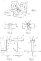
- Figure 1 shows schematically the interior view of a vehicle interior which shows two independent front seats (1 and 2) between which the space is filled by the presence of the armrest (3).
- This armrest provides an upper support surface (4) on which the driver and / or passenger can rest an arm.
- the width of the support surface will be adapted so that each of the users can benefit from it.
- the armrest has a frame, generally identified in (5) in Figure 1, adapted to be interposed between the seats (1) and (2) and removably.
- a rack provided on one of the two elements will, for example, form notches and define fixed positions.
- the armrest of the present invention comprises fixing means generally identified by (6) in the figures, capable of bearing at least at the level of the competition zone of the backrest (7) and of the seat (8 ) of each front seat.
- the fixing means (6) are in the form of a rod (9) integral with the frame (5) and transverse relative to the longitudinal axis of the vehicle and the armrest, axis marked (10).
- the rod (9) can be constituted by a metal bar of circular section, for example rectilinear.
- this rod (9) which will constitute the fulcrum at the level of the backrest area (7) and the seat (8) of each front seat.
- this zone that is to say the angle (11) formed by the backrest (7) and the seat (8), has a constant height relative to the vehicle floor.
- the angle (11) moves parallel to the floor. If the backrest is tilted forward or backward, the edge of this angle also remains at constant height. It is the same when raising or lowering the seat (8) which is done around the edge of the angle (11).
- the frame (5) and the rod (9) will be connected using a vertical element (12) such as for example a flat welded on the one hand to the rod and on the other hand to the frame.
- the fixing means of the present invention advantageously comprise a second independent rod (13) and joined to the first rod (9).
- first rod (9) and the second rod (13) are joined by elastic means (14) so that each backrest (7), at least partially at said angle ( 11), or sandwiched between the rods (9 and 13).
- These elastic means (14) consist of one or more flexible links and Figure 6 shows the use of two elastic bracelets.
- the rod (13) may consist of two parallel bars connected by perpendicular spacers.
- FIG. 7 shows the use of a link (15) equipped at its ends with hooks (16). The latter are for example hooked to the rod (9) then the link is wound around the rod (13) and the element (12) connecting the rod (9) and the frame (5).
- Such a fixing has the advantage of being able to adapt to the various configurations of the vehicles and does not require drilling or the like of the bodywork.
- the rod (9), in the case of these elastic means, advantageously constitutes the axis of a hinge and it will be possible to place the bearing surface (4) vertically by rotation of the armrest around the rod (9).
- the armrest (3) of the present invention has means of articulation of the frame (5) relative to the fixing means (6) for adjusting the longitudinal axis of the armrest.
- the front seats (1, 2) are capable of being adjusted independently of one another. Under these conditions, it is necessary to be able to place the longitudinal axis (10) of the armrest in coincidence with that of the vehicle.
- Figure 2 shows the two seats placed one same level while Figure 3 shows an offset between the two seats.
- the fixing means (6) do not constitute a handicap for the separate adjustment of the seats because the rod (9), the links (14) and the second rod (13) constitute a quadrilateral deformable depending on the situation.
- Figures 4 to 6 show an embodiment of the articulation means (17). They consist of an axis of rotation (18) of the frame (5) relative to the fixing means (6, 9, 12 and 13) cooperating with a device (19) for locking said frame (5) in a chosen position.
- This locking device (19) is in the form of a circular lumen (20), coaxial with said axis of rotation (19), passed through by a clamping member (21) capable of binding the armature (5) and the fixing means (6) and particularly the horizontal U-shaped profile (22) constituting the part of the frame (5) intended to support the bearing surface (4).
- the light (20) it is constituted for example in a flat fixed perpendicular to the element (12) connecting the frame and the first rod (9) as shown in particular in Figures 4 and 6 .
- the armrest has means for stabilizing (23) the frame (5) capable of constituting a support point (24) complementary to the vehicle. These means (23) will stabilize the support surface (4) horizontally and adapt the height between it and the support surface.
- these stabilization means (23) will for example consist of at least one telescopic foot (25), integral with the frame (5) and the end of which will allow said support (24) to take up in space separating the two front seats.
- the telescopic foot is constituted by two concentric and nestable tubes, immobilized for example by a screw locking button (26).
- the armrest as illustrated in FIGS. 4 to 6 can be raised vertically between the front seats thanks to the rotation of the whole assembly with respect to the rod (9).
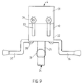
- FIG. 8 shows a second variant of an armrest according to the invention, which constitutes another embodiment and whose merits are just as interesting and important as the first.
- the frame (5) is made in two parts, an upper part (31) and a lower part (32).
- the connecting piece (12) is therefore made in two parts which has longitudinal slots (33).
- the two parts (12) are immobilized with respect to each other by means of a nut and a screw (34) ensuring adjustment and tightening. It is also possible to bring the parts (31 and 32) closer or further apart to vary the distance of the bearing surface (4) from the bearing point (24) of the telescopic leg (25).
- the longitudinal lights (33) also have the advantage of being able to adapt the armrest to the morphology of the driver and it is possible to adjust more or less the height of the vertical element (12) depending on whether the driver will have a more or less less long.
- the rod (9) is no longer straight, but on the contrary has been produced with curves (35). This configuration allows you to adapt sometimes to higher handbrake consoles. It should also be noted that in certain cases, the production of a rod (9) in two parts (36 and 37) may have an advantage when, in order to adapt to different shapes of seats, it is sought to bring together or separate the two parts (36, 37) relative to each other. This will also happen when, depending on the type of vehicle, the central spacing between the two seats is variable.
- Collars (38) are available for this, which tighten the rods (36 and 37) on the lower part (32) of the frame. This adjustment will be made to obtain a good positioning of the rod (9) in the angle (11) as shown in FIG. 4.
- the positioning of the bent rod (9) is carried out in the same way as the first variant as regards at least the contact at the level of the seat and the support in the area (11) of competition of the backrest (7) and the seat (8).
- the position of the armrest and its maintenance have not changed on this subject and the bent rod (9) is made in two parts, which makes it possible to escape certain obstacles and to make additional adjustments for even better s '' adapt to vehicles.
- the second alternative embodiment shown in FIG. 8 also includes articulation means constituted by an axis of rotation of the armature (5) relative to the fixing means (9, 36, 37) cooperating with a device for blocking of this armature in a chosen position.
- This device which is in the form of a circular lumen coaxial with the axis of rotation (18) is traversed by a clamping member (21). These elements are not visible in Figure 8.
- first adjustment constituted by grooves (39), for example four in number in which the ends (40) of a pin (41) may be clipped.
- the telescopic foot (25) is traversed right through by this axis and the base of the foot (42) is dimensioned to come to bear on the bottom (43) of the armrest.
- grooves (39) are produced inside the two faces (45 and 46) and that they are therefore neither visible nor accessible.
- a rubber brake (44) On the axis (41), a rubber brake (44) has also been engaged, making it possible to obtain an additional adjustment for the situation of the surface of the fulcrum (24) in space and therefore for the search for the best possible position depending on the vehicle.
- This rubber brake in fact allows the base (42) of the foot (25) to slide in a very fine and sensitive manner in the axis (41). It is thus seen that, for a determined position of the axis (41) in a groove (39), it will be possible to take the foot (25) with the brake (44) many positions in which this foot will either closer to the wall (45) is closer to the wall (46).
- this mounting will preferably be carried out with the seats in the same alignment.
- the rod (9) will be placed in the support area of the seats and an adjustment will therefore be made of the longitudinal lights (33) which must adapt to the driver's arm in order to have a support surface (4) more or lower.
- the armrest is placed behind the handbrake and therefore does not interfere with its control. Likewise, seat belts remain very accessible.
Landscapes
- Engineering & Computer Science (AREA)
- Aviation & Aerospace Engineering (AREA)
- Transportation (AREA)
- Mechanical Engineering (AREA)
- Seats For Vehicles (AREA)
Applications Claiming Priority (2)
| Application Number | Priority Date | Filing Date | Title |
|---|---|---|---|
| FR9206656 | 1992-05-25 | ||
| FR9206656A FR2691413B1 (fr) | 1992-05-25 | 1992-05-25 | Accoudoir pour sieges avant de vehicule. |
Publications (2)
| Publication Number | Publication Date |
|---|---|
| EP0572345A1 true EP0572345A1 (de) | 1993-12-01 |
| EP0572345B1 EP0572345B1 (de) | 1996-11-20 |
Family
ID=9430347
Family Applications (1)
| Application Number | Title | Priority Date | Filing Date |
|---|---|---|---|
| EP93490009A Expired - Lifetime EP0572345B1 (de) | 1992-05-25 | 1993-04-30 | Armlehne für einen Vordersitz eines Fahrzeuges |
Country Status (3)
| Country | Link |
|---|---|
| EP (1) | EP0572345B1 (de) |
| DE (1) | DE69306038T2 (de) |
| FR (1) | FR2691413B1 (de) |
Cited By (2)
| Publication number | Priority date | Publication date | Assignee | Title |
|---|---|---|---|---|
| FR2801853A1 (fr) * | 1999-12-04 | 2001-06-08 | Daimler Chrysler Ag | Casier de rangement dans un vehicule |
| FR2862581A1 (fr) * | 2003-11-24 | 2005-05-27 | Renault Sas | Module d'accessoires amovible pour vehicule automobile |
Families Citing this family (1)
| Publication number | Priority date | Publication date | Assignee | Title |
|---|---|---|---|---|
| DE102004038059A1 (de) * | 2004-07-30 | 2006-02-16 | Faurecia Innenraum Systeme Gmbh | Mittelkonsole mit einer höhenverstellbaren Armlehne |
Citations (5)
| Publication number | Priority date | Publication date | Assignee | Title |
|---|---|---|---|---|
| US2043626A (en) * | 1932-10-03 | 1936-06-09 | Willard L Morrison | Arm rest |
| US2563922A (en) * | 1946-11-15 | 1951-08-14 | Francis J Collins | Armrest |
| FR1082209A (fr) * | 1953-08-08 | 1954-12-28 | Accoudoir amovible et réglable pour sièges de véhicules | |
| GB1037972A (en) * | 1961-07-24 | 1966-08-03 | British Europ Airways Corp | Improvements in reclining seats |
| FR2633566A1 (fr) * | 1988-06-30 | 1990-01-05 | Vandamme Georges | Accoudoir pour siege avant de vehicule |
Family Cites Families (1)
| Publication number | Priority date | Publication date | Assignee | Title |
|---|---|---|---|---|
| BE361869A (de) * |
-
1992
- 1992-05-25 FR FR9206656A patent/FR2691413B1/fr not_active Expired - Fee Related
-
1993
- 1993-04-30 EP EP93490009A patent/EP0572345B1/de not_active Expired - Lifetime
- 1993-04-30 DE DE69306038T patent/DE69306038T2/de not_active Expired - Fee Related
Patent Citations (5)
| Publication number | Priority date | Publication date | Assignee | Title |
|---|---|---|---|---|
| US2043626A (en) * | 1932-10-03 | 1936-06-09 | Willard L Morrison | Arm rest |
| US2563922A (en) * | 1946-11-15 | 1951-08-14 | Francis J Collins | Armrest |
| FR1082209A (fr) * | 1953-08-08 | 1954-12-28 | Accoudoir amovible et réglable pour sièges de véhicules | |
| GB1037972A (en) * | 1961-07-24 | 1966-08-03 | British Europ Airways Corp | Improvements in reclining seats |
| FR2633566A1 (fr) * | 1988-06-30 | 1990-01-05 | Vandamme Georges | Accoudoir pour siege avant de vehicule |
Cited By (3)
| Publication number | Priority date | Publication date | Assignee | Title |
|---|---|---|---|---|
| FR2801853A1 (fr) * | 1999-12-04 | 2001-06-08 | Daimler Chrysler Ag | Casier de rangement dans un vehicule |
| FR2862581A1 (fr) * | 2003-11-24 | 2005-05-27 | Renault Sas | Module d'accessoires amovible pour vehicule automobile |
| EP1535793A1 (de) * | 2003-11-24 | 2005-06-01 | Renault s.a.s. | Entfernbares Zubehörteil für Kraftfahrzeuge |
Also Published As
| Publication number | Publication date |
|---|---|
| DE69306038T2 (de) | 1997-06-19 |
| FR2691413B1 (fr) | 1997-05-23 |
| DE69306038D1 (de) | 1997-01-02 |
| EP0572345B1 (de) | 1996-11-20 |
| FR2691413A1 (fr) | 1993-11-26 |
Similar Documents
| Publication | Publication Date | Title |
|---|---|---|
| EP2253502B1 (de) | Autokindersitz | |
| EP1152918B1 (de) | Kindersitz mit in der breite verstellbarer rückenlehne | |
| EP1544035A1 (de) | Vorderer Karosserieaufbau eines Kraftfahrzeuges mit verbesserten Befestigungs- und Lagejustiermitteln, und Kraftfahrzeug ausgestattet mit einem solchen Aufbau | |
| EP0343026A2 (de) | Anordnung eines Sitzes auf einem Fahrzeugboden | |
| FR2676690A1 (fr) | Plateau formant base tournante pour siege de vehicule. | |
| EP0572345B1 (de) | Armlehne für einen Vordersitz eines Fahrzeuges | |
| FR2689825A1 (fr) | Appui-tête pour siège de véhicule automobile. | |
| FR2862850A1 (fr) | Ensemble de relaxation pour l'ameublement ou l'automobile, du type canape, fauteuil ou siege transformable, pouvant fonctionner en etant positionne directement contre une paroi | |
| FR3099430A1 (fr) | Dispositif d’appui-tête et siège de véhicule comportant un tel appui-tête | |
| FR2773760A1 (fr) | Poussette pour enfant, a hamac allongeable telescopique, et hamac correspondant | |
| FR3074767A1 (fr) | Siege a support lombaire et vehicule comportant un tel siege | |
| EP0566501A1 (de) | Gelenk für ein Element eines umklappbaren Sitzes | |
| EP1211128A1 (de) | Sitzanordnung für Kraftfahrzeuge | |
| FR2780924A1 (fr) | Structure d'appuie-tete pour sieges | |
| FR2876327A1 (fr) | Appui-tete comprenant un element d'appui cervical | |
| EP1414668A1 (de) | Verstellbare fahrzeugsitzbank | |
| FR2966096A1 (fr) | Siege escamotable pour vehicule automobile | |
| FR2758297A1 (fr) | Appui-tete a coussin fixe et a coussin mobile | |
| FR2863965A1 (fr) | Accoudoir pour siege de vehicule automobile, console et siege portant cet accoudoir. | |
| FR2752548A1 (fr) | Dispositif formant appui-tete pour siege de vehicule automobile | |
| FR3131257A1 (fr) | Siège de véhicule doté d’un dossier modulable | |
| EP1530928A1 (de) | Zusammenklappbarer Stuhl mit einem niedrigen Profil in der zusammengeklappten Position | |
| EP2868519A1 (de) | Versenkbarer Sitz mit Kippsicherung | |
| FR3167088A1 (fr) | Banquette d’un véhicule automobile et véhicule automobile | |
| FR2877280A1 (fr) | Siege pour vehicule automobile mobile selon un premier axe x et un second axe y et vehicule automobile comprenant un tel siege |
Legal Events
| Date | Code | Title | Description |
|---|---|---|---|
| PUAI | Public reference made under article 153(3) epc to a published international application that has entered the european phase |
Free format text: ORIGINAL CODE: 0009012 |
|
| AK | Designated contracting states |
Kind code of ref document: A1 Designated state(s): BE DE ES FR GB IT NL |
|
| 17P | Request for examination filed |
Effective date: 19940201 |
|
| 17Q | First examination report despatched |
Effective date: 19950630 |
|
| GRAG | Despatch of communication of intention to grant |
Free format text: ORIGINAL CODE: EPIDOS AGRA |
|
| GRAH | Despatch of communication of intention to grant a patent |
Free format text: ORIGINAL CODE: EPIDOS IGRA |
|
| GRAH | Despatch of communication of intention to grant a patent |
Free format text: ORIGINAL CODE: EPIDOS IGRA |
|
| GRAA | (expected) grant |
Free format text: ORIGINAL CODE: 0009210 |
|
| AK | Designated contracting states |
Kind code of ref document: B1 Designated state(s): BE DE ES FR GB IT NL |
|
| PG25 | Lapsed in a contracting state [announced via postgrant information from national office to epo] |
Ref country code: NL Free format text: LAPSE BECAUSE OF FAILURE TO SUBMIT A TRANSLATION OF THE DESCRIPTION OR TO PAY THE FEE WITHIN THE PRESCRIBED TIME-LIMIT Effective date: 19961120 Ref country code: ES Free format text: THE PATENT HAS BEEN ANNULLED BY A DECISION OF A NATIONAL AUTHORITY Effective date: 19961120 |
|
| ITF | It: translation for a ep patent filed | ||
| REF | Corresponds to: |
Ref document number: 69306038 Country of ref document: DE Date of ref document: 19970102 |
|
| GBT | Gb: translation of ep patent filed (gb section 77(6)(a)/1977) |
Effective date: 19970124 |
|
| PGFP | Annual fee paid to national office [announced via postgrant information from national office to epo] |
Ref country code: GB Payment date: 19970428 Year of fee payment: 5 |
|
| PGFP | Annual fee paid to national office [announced via postgrant information from national office to epo] |
Ref country code: FR Payment date: 19970429 Year of fee payment: 5 |
|
| NLV1 | Nl: lapsed or annulled due to failure to fulfill the requirements of art. 29p and 29m of the patents act | ||
| PGFP | Annual fee paid to national office [announced via postgrant information from national office to epo] |
Ref country code: DE Payment date: 19970509 Year of fee payment: 5 |
|
| PGFP | Annual fee paid to national office [announced via postgrant information from national office to epo] |
Ref country code: BE Payment date: 19970529 Year of fee payment: 5 |
|
| PLBE | No opposition filed within time limit |
Free format text: ORIGINAL CODE: 0009261 |
|
| STAA | Information on the status of an ep patent application or granted ep patent |
Free format text: STATUS: NO OPPOSITION FILED WITHIN TIME LIMIT |
|
| 26N | No opposition filed | ||
| PG25 | Lapsed in a contracting state [announced via postgrant information from national office to epo] |
Ref country code: GB Free format text: LAPSE BECAUSE OF NON-PAYMENT OF DUE FEES Effective date: 19980430 Ref country code: FR Free format text: THE PATENT HAS BEEN ANNULLED BY A DECISION OF A NATIONAL AUTHORITY Effective date: 19980430 Ref country code: BE Free format text: LAPSE BECAUSE OF NON-PAYMENT OF DUE FEES Effective date: 19980430 |
|
| BERE | Be: lapsed |
Owner name: VANDAMME GEORGES Effective date: 19980430 |
|
| GBPC | Gb: european patent ceased through non-payment of renewal fee |
Effective date: 19980430 |
|
| PG25 | Lapsed in a contracting state [announced via postgrant information from national office to epo] |
Ref country code: DE Free format text: LAPSE BECAUSE OF NON-PAYMENT OF DUE FEES Effective date: 19990202 |
|
| REG | Reference to a national code |
Ref country code: FR Ref legal event code: ST |
|
| PG25 | Lapsed in a contracting state [announced via postgrant information from national office to epo] |
Ref country code: IT Free format text: LAPSE BECAUSE OF NON-PAYMENT OF DUE FEES;WARNING: LAPSES OF ITALIAN PATENTS WITH EFFECTIVE DATE BEFORE 2007 MAY HAVE OCCURRED AT ANY TIME BEFORE 2007. THE CORRECT EFFECTIVE DATE MAY BE DIFFERENT FROM THE ONE RECORDED. Effective date: 20050430 |