EP0572300A1 - Device for locking a seat belt anchor on contacting a motor vehicle floor - Google Patents
Device for locking a seat belt anchor on contacting a motor vehicle floor Download PDFInfo
- Publication number
- EP0572300A1 EP0572300A1 EP93401277A EP93401277A EP0572300A1 EP 0572300 A1 EP0572300 A1 EP 0572300A1 EP 93401277 A EP93401277 A EP 93401277A EP 93401277 A EP93401277 A EP 93401277A EP 0572300 A1 EP0572300 A1 EP 0572300A1
- Authority
- EP
- European Patent Office
- Prior art keywords
- seat
- lock
- housing
- floor
- latch
- Prior art date
- Legal status (The legal status is an assumption and is not a legal conclusion. Google has not performed a legal analysis and makes no representation as to the accuracy of the status listed.)
- Withdrawn
Links
- 230000014759 maintenance of location Effects 0.000 claims abstract description 6
- 230000000694 effects Effects 0.000 claims description 3
- 230000001681 protective effect Effects 0.000 description 4
- 238000004873 anchoring Methods 0.000 description 3
- 238000004519 manufacturing process Methods 0.000 description 3
- 230000005540 biological transmission Effects 0.000 description 1
- 239000006185 dispersion Substances 0.000 description 1
- 238000002513 implantation Methods 0.000 description 1
- 238000005192 partition Methods 0.000 description 1
- 230000002028 premature Effects 0.000 description 1
- 230000002787 reinforcement Effects 0.000 description 1
- 230000000717 retained effect Effects 0.000 description 1
Images
Classifications
-
- B—PERFORMING OPERATIONS; TRANSPORTING
- B60—VEHICLES IN GENERAL
- B60R—VEHICLES, VEHICLE FITTINGS, OR VEHICLE PARTS, NOT OTHERWISE PROVIDED FOR
- B60R22/00—Safety belts or body harnesses in vehicles
- B60R22/18—Anchoring devices
- B60R22/26—Anchoring devices secured to the seat
Definitions
- the invention relates to devices for locking in contact with a motor vehicle floor a seat belt anchor.
- the invention relates more particularly to the locking of seat belt anchorages carried by a tilting seat frame around a transverse axis disposed at the front of said frame, of the type comprising an articulated lock integral with said anchorage and intended to be retained in a keeper rigidly connected to the vehicle floor.
- the anchoring carried by the floor consists of a receiving part with which a movable lock cooperates with the seat of a seat in order to obtain the self-locking of the point d hanging of the belt with the floor when the seat occupies its position of use.
- the movable lock with the seat is made integral with the anchoring carried by the floor when the seat and the belt are in the position of use.
- Publication FR-A-2,519,867 describes a device for self-locking a seat belt fastener carried by the seat of a seat with an anchor fixed to the floor.
- the retention of the fastener is carried out under the effect of a locking force operated by the backrest in the position of use of the seat.
- the tilting seat arranged so as to give the vehicle a modifiable loading volume will then have reduced job security, especially during a collision.
- the present invention relates to an anchoring device for a seat belt of a folding seat such as an individual seat or a seat which provides a solution to the above problems.
- the invention therefore starts from the idea that it is necessary to preserve the various elements of the device from a risk of premature wear capable of reducing the safety of use of the seat belt and noise generator during the vehicle operation.
- the lock is mounted for rotation in a pivoting box carried by the seat frame and said box is in contact with support on the edge of the keeper in order to simultaneously establish the support of the box on the strike and the retention of the lock in contact with the strike.
- the device thus produced allows in particular the production of seat belt anchorages carried by a sliding and tilting seat, without requiring reinforcements at the level of the frames or the slides of said seat.
- the device also makes it possible to maintain the quality of operation of the device taking into account the dispersion of the manufacturing tolerances of the components of the seat, of the vehicle and of the device.
- the passenger compartment 10 of a vehicle defined by its body 11, has two rows of adjustable seats individually attached to the floor 12 of the vehicle.
- the backrests 14, 15 of the rear seat constitute a partition separating the passenger compartment 10 from the luggage compartment 13.
- the seat of said seats constitutes a convertible bench seat 16 mounted in translation on the floor 12 using slides 20, 20 '.
- the bench seat 16 is supported by a frame forming a shell 17 which swings around a transverse axis 18 disposed at the front of said shell.
- the rear part of the shell carries a transverse stiffening tube 21 welded to the shell as shown in FIG. 2.
- the middle part of the tube 21 carries a support 22 rigidly connected to said tube on which is located an intermediate bearing 23 of the articulated frames of the files 14, 15.
- the support 22 also carries the mounting pin 24 of a protective housing 25 d 'an immobilization lock 26 which secures the seat 16 with the floor 12.
- the lock 26 is rotatably mounted about an axis 27 carried by the housing 25 and the latter has a support area of a branch 28 d 'a return spring 30 of the housing 25 and the latch 26 in a locking position.
- the other branch 29 of the spring 30 is supported on the support 22.
- the housing 25 also carries two support pads 32 intended to rest on the floor 12 by means of a profile 36 under the action of the spring 30.
- the latch 26 also carries an actuating finger 31 on which the operating member 33 rests.
- the latch 26 is engaged on a cross member 35 for the longitudinal positioning of the seat, rigidly fixed to the floor 12 by means of a U-shaped profile 36 forming a keeper.
- the profile 36 carries a succession of crosspieces 35 welded to said profile in order to transmit the forces between keeper 36 and latch 26 when the seat 16 is positioned longitudinally by means of the slides 20, 20 '.
- the bench seat 16 is fixed by means of the shell 17 to the respective upper profiles of the slides 20, 20 '.
- the axis of rotation 27 of the lock 26 extends transversely to the outside of the lateral flanks 40 of the protective housing 25 and carries two anchorages for seat belts 42 constituted by receiving housings 43 and engaging bolts 44 mounted sliding on the respective straps of the belts 42.
- the axis of rotation 27 of the latch 26 comprises in its middle part a square section which ensures the simultaneous drive of the latch 26 and a latching lever 45.
- the lever 45 is connected by a return spring 46, mounted in tension between the end of the lever 45 to a hooking lug carried by the housing 25.
- the spring 46 thus keeps the lock 26 in permanent contact with the crosspieces 35 carried by the profile 36.
- the device thus produced simultaneously ensures the support of the housing 25 on the keeper 36 and the retention of the bolt 26 in contact with any one of the crosspieces 35.
- the receiving housings 43 of the bolts 44 are moreover orientable relative to the axis 27 of rotation of the lock, and allow the transmission of an engagement force FD of the lock on the cross-member 35, under the effect of a tension force exerted on one and / or the other housing 43.
Landscapes
- Engineering & Computer Science (AREA)
- Mechanical Engineering (AREA)
- Seats For Vehicles (AREA)
Abstract
Dispositif de verrouillage au contact d'un plancher (12) de véhicule, d'un ancrage (43) de ceinture de sécurité porté par une armature (17) de siège basculante autour d'un axe transversal disposé à l'avant de ladite armature, du type comportant un verrou (26) articulé solidaire dudit ancrage (43) et destiné à coopérer avec une gâche (36) rigidement reliée au plancher, caractérisé par le fait que le verrou (26) est monté à rotation, dans un boîtier pivotant (25) porté par l'armature du siège et que ledit boîtier (25) est en contact d'appui sur le bord de la gâche (36) dans le but d'établir simultanément l'appui du boîtier (25) sur la gâche (36) et la retenue du verrou (26) au contact de la gâche.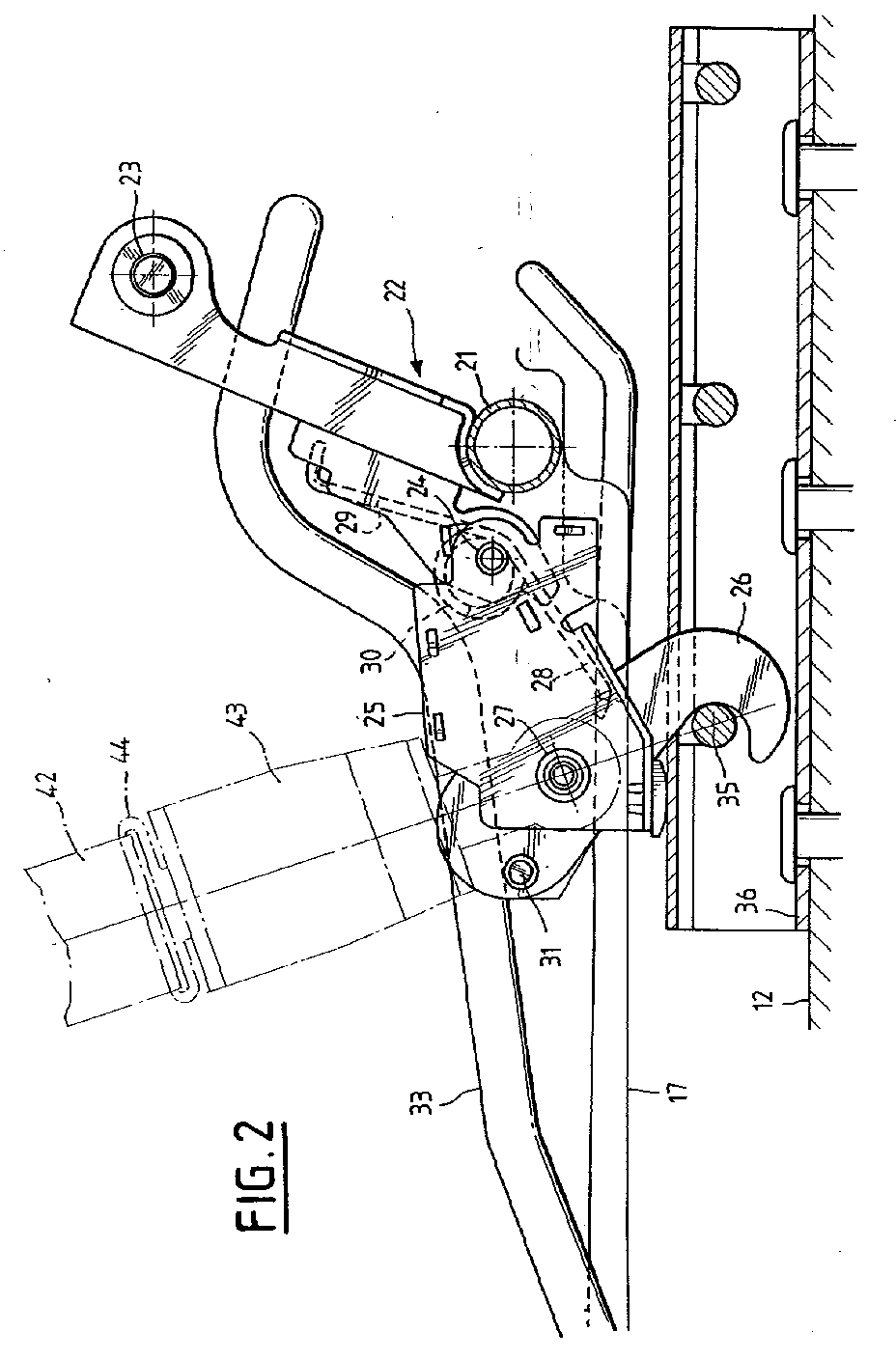
Description
L'invention concerne les dispositifs de verrouillage au contact d'un plancher de véhicule automobile d'un ancrage de ceinture de sécurité .The invention relates to devices for locking in contact with a motor vehicle floor a seat belt anchor.
L'invention concerne plus particulièrement les verrouillages d'ancrages de ceinture de sécurité portés par une armature de siège basculante autour d'un axe transversal disposé à l'avant de ladite armature, du type comportant un verrou articulé solidaire dudit ancrage et destiné à être retenu dans une gâche rigidement reliée au plancher du véhicule.The invention relates more particularly to the locking of seat belt anchorages carried by a tilting seat frame around a transverse axis disposed at the front of said frame, of the type comprising an articulated lock integral with said anchorage and intended to be retained in a keeper rigidly connected to the vehicle floor.
Selon la publication FR-A- 2 463 024, l'ancrage porté par le plancher est constitué par une pièce de réception avec laquelle coopère un verrou mobile avec la banquette d'un siège dans le but d'obtenir l'autoverrouillage du point d'accrochage de la ceinture avec le plancher lorsque le siège occupe sa position d'utilisation.According to the publication FR-A- 2 463 024, the anchoring carried by the floor consists of a receiving part with which a movable lock cooperates with the seat of a seat in order to obtain the self-locking of the point d hanging of the belt with the floor when the seat occupies its position of use.
Selon la publication FR-A-2 422 528, le verrou mobile avec l'assise est rendu solidaire avec l'ancrage porté par le plancher lorsque le siège et la ceinture sont en position d'utilisation.According to publication FR-A-2 422 528, the movable lock with the seat is made integral with the anchoring carried by the floor when the seat and the belt are in the position of use.
La publication FR-A-2 519 867 décrit un dispositif d'autoverrouillage d'une attache de ceinture de sécurité portée par l'assise d'un siège avec un ancrage fixé au plancher. La retenue de l'attache est réalisée sous l'effet d'un effort de verrouillage opéré par le dossier dans la position d'utilisation du siège.Publication FR-A-2,519,867 describes a device for self-locking a seat belt fastener carried by the seat of a seat with an anchor fixed to the floor. The retention of the fastener is carried out under the effect of a locking force operated by the backrest in the position of use of the seat.
Les dispositifs précités posent toutefois un problème en ce qui concerne l'ajustement du verrou dans la gâche, lorsque l'armature du siège est montée à coulissement longitudinal le long du plancher.The aforementioned devices, however, pose a problem with regard to the adjustment of the latch in the keeper, when the seat frame is mounted to slide longitudinally along the floor.
Dans une telle configuration les variations constatées des niveaux respectifs du plancher et des coulisses du siège ont pour résultat une retenue imparfaite du verrou dans la gâche et les bruits de fonctionnement qui en résultent nécessitent l'emploi de moyens d'ajustement et un calage incompatibles avec le montage en grande série des sièges de véhicules.In such a configuration, the variations observed in the respective levels of the floor and of the seat slides result in imperfect retention of the latch in the keeper and the resulting operating noises require the use of adjustment means and a setting incompatible with mass production of vehicle seats.
Au cours de la vie du véhicule, le siège basculant, agencé de manière à conférer au véhicule un volume de chargement modifiable aura alors une sécurité d'emploi réduite notamment au cours d'une collision.During the life of the vehicle, the tilting seat, arranged so as to give the vehicle a modifiable loading volume will then have reduced job security, especially during a collision.
La présente invention a pour objet un dispositif d'ancrage pour une ceinture de sécurité d'un siège repliable tel qu'un siège individuel ou d'une banquette qui apporte une solution aux problèmes précités.The present invention relates to an anchoring device for a seat belt of a folding seat such as an individual seat or a seat which provides a solution to the above problems.
L'invention part donc de l'idée selon laquelle il est nécessaire de préserver les divers éléments du dispositif d'un risque d'usure prématurée susceptible de réduire la sécurité d'emploi de la ceinture de sécurité et génératrice de bruits au cours de l'exploitation du véhicule.The invention therefore starts from the idea that it is necessary to preserve the various elements of the device from a risk of premature wear capable of reducing the safety of use of the seat belt and noise generator during the vehicle operation.
Selon l'invention le verrou est monté à rotation dans un boîtier pivotant porté par l'armature du siège et ledit boîtier est en contact d'appui sur le bord de la gâche dans le but d'établir simultanément l'appui du boîtier sur la gâche et la retenue du verrou en contact de la gâche.According to the invention, the lock is mounted for rotation in a pivoting box carried by the seat frame and said box is in contact with support on the edge of the keeper in order to simultaneously establish the support of the box on the strike and the retention of the lock in contact with the strike.
Le dispositif ainsi réalisé permet notamment la réalisation d'ancrages de ceintures de sécurité portées par un siège coulissant et basculant, sans nécessiter de renforcements au niveau des armatures ou des glissières dudit siège.The device thus produced allows in particular the production of seat belt anchorages carried by a sliding and tilting seat, without requiring reinforcements at the level of the frames or the slides of said seat.
Le dispositif permet également le maintien de la qualité de fonctionnement du dispositif compte tenu de la dispersion des tolérances de fabrication des composants du siège, du véhicule et du dispositif.The device also makes it possible to maintain the quality of operation of the device taking into account the dispersion of the manufacturing tolerances of the components of the seat, of the vehicle and of the device.
On a décrit ci-après à titre d'exemple, un mode de réalisation du dispositif de verrouillage en référence au dessin annexé dans lequel :
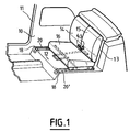
- la figure 1 est une représentation schématique de l'implantation d'un siège de véhicule automobile portant l'ancrage de la ceinture de sécurité conforme à l'invention.
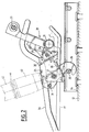
- la figure 2 est une vue en coupe médiane de la partie arrière de l'armature basculante d'un siège de véhicule équipée du dispositif de verrouillage conforme à l'invention.
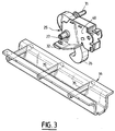
- la figure 3 est une représentation perspective du verrou et de la gâche de réception.
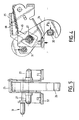
- la figure 4 est une représentation latérale du verrou et de la répartition des efforts exercés sur ledit verrou et sur son boîtier de protection.
- la figure 5 est une vue en coupe longitudinale du boîtier de protection du verrou.
- Figure 1 is a schematic representation of the layout of a motor vehicle seat carrying the anchor of the seat belt according to the invention.
- Figure 2 is a median sectional view of the rear part of the tilting frame of a vehicle seat equipped with the locking device according to the invention.
- Figure 3 is a perspective representation of the latch and the strike plate.
- Figure 4 is a side representation of the lock and the distribution of the forces exerted on said lock and on its protective housing.
- Figure 5 is a longitudinal sectional view of the protective housing of the lock.
Ainsi que cela est représenté à la figure 1, l'habitacle 10 d'un véhicule défini par sa carrosserie 11, possède deux rangées de sièges réglables fixées individuellement sur le plancher 12 du véhicule.As shown in Figure 1, the
Les dossiers 14, 15 du siège arrière constituent une cloison de séparation de l'habitacle 10 avec le compartiment à bagages 13. L'assise desdits sièges constitue une banquette 16 transformable montée à translation sur le plancher 12 à l'aide de glissières 20, 20'.The
La banquette 16 est supportée par une armature formant une coquille 17 qui bascule autour d'un axe transversal 18 disposé à l'avant de ladite coquille. La partie postérieure de la coquille porte un tube de rigidification transversal 21 soudé à la coquille comme cela est montré à la figure 2.The
La partie médiane du tube 21 porte un support 22 rigidement relié audit tube sur lequel est localisé un palier intermédiaire 23 des armatures articulées des dossiers 14, 15. Le support 22 porte également l'axe de montage 24 d'un boîtier de protection 25 d'un verrou d'immobilisation 26 qui solidarise la banquette 16 avec le plancher 12. Le verrou 26 est monté à rotation autour d'un axe 27 porté par le boîtier 25 et ce dernier possède une zone d'appui d'une branche 28 d'un ressort de rappel 30 du boîtier 25 et du verrou 26 dans une position de verrouillage. L'autre branche 29 du ressort 30 est en appui sur le support 22.The middle part of the
Le boîtier 25 porte également deux patins 32 d'appui destinés à reposer sur le plancher 12 par l'intermédiaire d'un profil 36 sous l'action du ressort 30.The
Le verrou 26 porte par ailleurs un doigt 31 d'actionnement sur lequel repose l'organe de manoeuvre 33.The
Ainsi que cela est montré sur la figure 2 ou 3, le verrou 26 est enclenché sur une traverse 35 de positionnement longitudinal de la banquette, rigidement fixée au plancher 12 par l'intermédiaire d'un profil en U 36 formant gâche. A cet effet le profil 36 porte une succession de traverses 35 soudées audit profil dans le but de transmettre les efforts entre gâche 36 et verrou 26 lorsque la banquette 16 est positionnée longitudinalement par l'intermédiaire des glissières 20, 20'.As shown in FIG. 2 or 3, the
La banquette 16 est fixée par l'intermédiaire de la coquille 17 sur les profils supérieurs respectifs des glissières 20, 20'.The
L'axe de rotation 27 du verrou 26 s'étend transversalement à l'extérieur des flancs latéraux 40 du boîtier de protection 25 et porte deux ancrages de ceintures de sécurité 42 constitués par des boîtiers de réception 43 et d'enclenchement des pênes 44 montés à coulissement sur les sangles respectives des ceintures 42.The axis of
L'axe de rotation 27 du verrou 26 comporte dans sa partie médiane un tronçon de section carrée qui assure l'entraînement simultané du verrou 26 et d'un levier d'accrochage 45. Le levier 45 est relié par un ressort de rappel 46, monté en tension entre l'extrémité du levier 45 à une patte d'accrochage portée par le boîtier 25.The axis of
Le ressort 46 maintient de la sorte le verrou 26 en contact permanent avec les traverses 35 portées par le profil 36.The
Le dispositif ainsi réalisé assure simultanément l'appui du boîtier 25 sur la gâche 36 et la retenue du verrou 26 au contact de l'une quelconque des traverses 35.The device thus produced simultaneously ensures the support of the
Les boîtiers de réception 43 des pènes 44 sont par ailleurs orientables par rapport à l'axe 27 de rotation du verrou, et permettent la transmission d'un effort d'engagement FD du verrou sur la traverse 35, sous l'effet d'un effort de tension exercé sur l'un et/ou l'autre boîtier 43.The
Claims (5)
Applications Claiming Priority (2)
| Application Number | Priority Date | Filing Date | Title |
|---|---|---|---|
| FR9206410 | 1992-05-26 | ||
| FR9206410A FR2691686B1 (en) | 1992-05-26 | 1992-05-26 | LOCKING DEVICE IN CONTACT WITH A MOTOR VEHICLE FLOOR, A SEAT BELT ANCHORAGE. |
Publications (1)
| Publication Number | Publication Date |
|---|---|
| EP0572300A1 true EP0572300A1 (en) | 1993-12-01 |
Family
ID=9430175
Family Applications (1)
| Application Number | Title | Priority Date | Filing Date |
|---|---|---|---|
| EP93401277A Withdrawn EP0572300A1 (en) | 1992-05-26 | 1993-05-18 | Device for locking a seat belt anchor on contacting a motor vehicle floor |
Country Status (2)
| Country | Link |
|---|---|
| EP (1) | EP0572300A1 (en) |
| FR (1) | FR2691686B1 (en) |
Cited By (5)
| Publication number | Priority date | Publication date | Assignee | Title |
|---|---|---|---|---|
| DE4414027C1 (en) * | 1994-04-22 | 1995-08-10 | Audi Ag | Rear seat bench for vehicle |
| GB2295321A (en) * | 1994-11-23 | 1996-05-29 | Kimberly Clark Co | Absorbent article having a composite absorbent core |
| FR2805228A1 (en) * | 2000-02-21 | 2001-08-24 | Faure Bertrand Equipements Sa | Anchorage plate, for seat belt fitting in vehicle, consists of one piece plate formed to have two or more attachment sites, consisting of striking plates formed as part of frame, which is fixed to vehicle structure. |
| FR2864494A1 (en) * | 2003-12-30 | 2005-07-01 | Renault Sas | VEHICLE FLOOR COMPRISING FASTENING HOUSINGS FOR SAFETY BELT BODIES |
| US12330585B1 (en) * | 2024-07-12 | 2025-06-17 | Taiwan Racing Products Co., Ltd. | Seat belt anchor |
Citations (1)
| Publication number | Priority date | Publication date | Assignee | Title |
|---|---|---|---|---|
| EP0457699A2 (en) * | 1990-05-16 | 1991-11-21 | Cesa Compagnie Europeenne De Sieges Pour Automobiles | Device for automatically coupling a safety belt anchorage to a vehicle floor |
-
1992
- 1992-05-26 FR FR9206410A patent/FR2691686B1/en not_active Expired - Lifetime
-
1993
- 1993-05-18 EP EP93401277A patent/EP0572300A1/en not_active Withdrawn
Patent Citations (1)
| Publication number | Priority date | Publication date | Assignee | Title |
|---|---|---|---|---|
| EP0457699A2 (en) * | 1990-05-16 | 1991-11-21 | Cesa Compagnie Europeenne De Sieges Pour Automobiles | Device for automatically coupling a safety belt anchorage to a vehicle floor |
Cited By (7)
| Publication number | Priority date | Publication date | Assignee | Title |
|---|---|---|---|---|
| DE4414027C1 (en) * | 1994-04-22 | 1995-08-10 | Audi Ag | Rear seat bench for vehicle |
| GB2295321A (en) * | 1994-11-23 | 1996-05-29 | Kimberly Clark Co | Absorbent article having a composite absorbent core |
| GB2295321B (en) * | 1994-11-23 | 1998-06-10 | Kimberly Clark Co | Absorbent article having a composite absorbent core |
| FR2805228A1 (en) * | 2000-02-21 | 2001-08-24 | Faure Bertrand Equipements Sa | Anchorage plate, for seat belt fitting in vehicle, consists of one piece plate formed to have two or more attachment sites, consisting of striking plates formed as part of frame, which is fixed to vehicle structure. |
| FR2864494A1 (en) * | 2003-12-30 | 2005-07-01 | Renault Sas | VEHICLE FLOOR COMPRISING FASTENING HOUSINGS FOR SAFETY BELT BODIES |
| WO2005073015A1 (en) * | 2003-12-30 | 2005-08-11 | Renault S.A.S. | Device for fixing a motor vehicle seat |
| US12330585B1 (en) * | 2024-07-12 | 2025-06-17 | Taiwan Racing Products Co., Ltd. | Seat belt anchor |
Also Published As
| Publication number | Publication date |
|---|---|
| FR2691686A1 (en) | 1993-12-03 |
| FR2691686B1 (en) | 1998-06-05 |
Similar Documents
| Publication | Publication Date | Title |
|---|---|---|
| EP0589759B1 (en) | Internal memory slide for positioning a seat | |
| FR2706381A1 (en) | Integrated child seat for motor vehicle seat. | |
| FR2835790A1 (en) | DEVICE FOR VERTICAL AND AUTOMATIC SETTING OF A VEHICLE SEAT | |
| FR2796015A1 (en) | DEVICE FOR ADJUSTING A DOUBLE ARTICULATED SEAT BACK BY A SINGLE CONTROL | |
| FR2663271A1 (en) | MOTOR VEHICLE SEAT SEAT EQUIPPED WITH A RISING CENTRAL PART TO RECEIVE A CHILD SEAT. | |
| FR2774045A1 (en) | VEHICLE SEAT, REMOVABLE, TURNABLE AND LONGITUDINALLY ADJUSTABLE | |
| FR2676975A1 (en) | SEAT DEVICE FOR CHILD PASSENGER, INTEGRATED WITH THE COMPONENT OF A MAIN MOTOR VEHICLE SEAT. | |
| EP0572300A1 (en) | Device for locking a seat belt anchor on contacting a motor vehicle floor | |
| FR2705627A1 (en) | Retractable seat for motor vehicles. | |
| EP0878347A1 (en) | Holder for a childrens' seat | |
| EP0311490B1 (en) | Safety belt holding mechanism with a manually adjustable position | |
| FR2828149A1 (en) | Locking mechanism for automobile foldable rear seat back comprises catch fixed on back and strike plate on bodywork, catch comprises reinforcing metal sheet supporting casing in which self-adjusting locking hook rotates | |
| FR2716423A1 (en) | Safety device integrated into vehicle seats | |
| FR2781731A1 (en) | ARRANGEMENT FOR LONGITUDINAL POSITION ADJUSTMENT AND FIXING OF AN INTERIOR FITTING ELEMENT OF A MOTOR VEHICLE | |
| EP1481839B1 (en) | Automotive vehicle provided with a reclinable rear bench. | |
| EP1964710B1 (en) | Anchoring system for a removable automotive vehicle seat | |
| FR2824799A1 (en) | Vehicle seat comprises back with upper part which can be moved frontward from its rest position where it is held by coupling part which releases upper part under inertia effect of weight during rear collision | |
| FR2870487A1 (en) | Head restraint for fixing e.g. child seat, has two units placed on either side of cushion and connected with each other by framework, where each unit has anchoring rod for anchoring upper part of child seat | |
| EP4282700B1 (en) | Seat for vehicle | |
| FR2859953A1 (en) | Detachable seat for vehicle, has front locking device with prong that supports base on floor pan of vehicle when seat pivots towards normal usage position and is elastically pushed to one position in absence of external support on base | |
| FR2697785A1 (en) | Secondary child's seat integrated into vehicle seat - with main seat back forms child's seat by pivoting around transverse horizontal axis | |
| FR2706409A1 (en) | Device for reversibly fastening a seat to the floor of a motor vehicle | |
| EP0047703B1 (en) | Height adjustment device for vehicle seats | |
| FR2848932A1 (en) | Vehicle seat head support, has case arranged to accommodate blockage unit and operating unit, where operating unit enables reversible displacement of blockage unit from position of blockage towards position of rotation | |
| FR3160656A1 (en) | Seat belt buckle attachment device |
Legal Events
| Date | Code | Title | Description |
|---|---|---|---|
| PUAI | Public reference made under article 153(3) epc to a published international application that has entered the european phase |
Free format text: ORIGINAL CODE: 0009012 |
|
| AK | Designated contracting states |
Kind code of ref document: A1 Designated state(s): DE ES GB IT |
|
| 17P | Request for examination filed |
Effective date: 19940516 |
|
| 17Q | First examination report despatched |
Effective date: 19950510 |
|
| STAA | Information on the status of an ep patent application or granted ep patent |
Free format text: STATUS: THE APPLICATION HAS BEEN WITHDRAWN |
|
| 18W | Application withdrawn |
Withdrawal date: 19950623 |