EP0571048B1 - Zusammenbau eines Bandes - Google Patents
Zusammenbau eines Bandes Download PDFInfo
- Publication number
- EP0571048B1 EP0571048B1 EP93201452A EP93201452A EP0571048B1 EP 0571048 B1 EP0571048 B1 EP 0571048B1 EP 93201452 A EP93201452 A EP 93201452A EP 93201452 A EP93201452 A EP 93201452A EP 0571048 B1 EP0571048 B1 EP 0571048B1
- Authority
- EP
- European Patent Office
- Prior art keywords
- belt
- unit
- portions
- toothed
- assembly according
- Prior art date
- Legal status (The legal status is an assumption and is not a legal conclusion. Google has not performed a legal analysis and makes no representation as to the accuracy of the status listed.)
- Expired - Lifetime
Links
- 230000014759 maintenance of location Effects 0.000 claims description 19
- 238000001514 detection method Methods 0.000 claims description 3
- 238000010276 construction Methods 0.000 description 7
- 238000005452 bending Methods 0.000 description 6
- 239000000969 carrier Substances 0.000 description 6
- 230000000712 assembly Effects 0.000 description 5
- 238000000429 assembly Methods 0.000 description 5
- 238000006073 displacement reaction Methods 0.000 description 4
- 230000007935 neutral effect Effects 0.000 description 3
- 238000003466 welding Methods 0.000 description 2
- 229920002430 Fibre-reinforced plastic Polymers 0.000 description 1
- 230000001133 acceleration Effects 0.000 description 1
- 230000000694 effects Effects 0.000 description 1
- 230000002349 favourable effect Effects 0.000 description 1
- 239000011151 fibre-reinforced plastic Substances 0.000 description 1
- 239000003292 glue Substances 0.000 description 1
- 238000001746 injection moulding Methods 0.000 description 1
- 238000004519 manufacturing process Methods 0.000 description 1
- 238000000034 method Methods 0.000 description 1
- 239000004033 plastic Substances 0.000 description 1
- 229920003023 plastic Polymers 0.000 description 1
- 230000000750 progressive effect Effects 0.000 description 1
- 230000002035 prolonged effect Effects 0.000 description 1
Images




Classifications
-
- B—PERFORMING OPERATIONS; TRANSPORTING
- B65—CONVEYING; PACKING; STORING; HANDLING THIN OR FILAMENTARY MATERIAL
- B65G—TRANSPORT OR STORAGE DEVICES, e.g. CONVEYORS FOR LOADING OR TIPPING, SHOP CONVEYOR SYSTEMS OR PNEUMATIC TUBE CONVEYORS
- B65G17/00—Conveyors having an endless traction element, e.g. a chain, transmitting movement to a continuous or substantially-continuous load-carrying surface or to a series of individual load-carriers; Endless-chain conveyors in which the chains form the load-carrying surface
- B65G17/30—Details; Auxiliary devices
- B65G17/38—Chains or like traction elements; Connections between traction elements and load-carriers
- B65G17/42—Attaching load carriers to traction elements
-
- B—PERFORMING OPERATIONS; TRANSPORTING
- B65—CONVEYING; PACKING; STORING; HANDLING THIN OR FILAMENTARY MATERIAL
- B65G—TRANSPORT OR STORAGE DEVICES, e.g. CONVEYORS FOR LOADING OR TIPPING, SHOP CONVEYOR SYSTEMS OR PNEUMATIC TUBE CONVEYORS
- B65G19/00—Conveyors comprising an impeller or a series of impellers carried by an endless traction element and arranged to move articles or materials over a supporting surface or underlying material, e.g. endless scraper conveyors
- B65G19/18—Details
- B65G19/22—Impellers, e.g. push-plates, scrapers; Guiding means therefor
- B65G19/24—Attachment of impellers to traction element
- B65G19/245—Attachment of impellers to traction element for article conveyors, e.g. for container conveyors
-
- F—MECHANICAL ENGINEERING; LIGHTING; HEATING; WEAPONS; BLASTING
- F16—ENGINEERING ELEMENTS AND UNITS; GENERAL MEASURES FOR PRODUCING AND MAINTAINING EFFECTIVE FUNCTIONING OF MACHINES OR INSTALLATIONS; THERMAL INSULATION IN GENERAL
- F16G—BELTS, CABLES, OR ROPES, PREDOMINANTLY USED FOR DRIVING PURPOSES; CHAINS; FITTINGS PREDOMINANTLY USED THEREFOR
- F16G3/00—Belt fastenings, e.g. for conveyor belts
- F16G3/08—Belt fastenings, e.g. for conveyor belts consisting of plates and screw-bolts or rivets
-
- B—PERFORMING OPERATIONS; TRANSPORTING
- B65—CONVEYING; PACKING; STORING; HANDLING THIN OR FILAMENTARY MATERIAL
- B65G—TRANSPORT OR STORAGE DEVICES, e.g. CONVEYORS FOR LOADING OR TIPPING, SHOP CONVEYOR SYSTEMS OR PNEUMATIC TUBE CONVEYORS
- B65G2201/00—Indexing codes relating to handling devices, e.g. conveyors, characterised by the type of product or load being conveyed or handled
- B65G2201/02—Articles
-
- B—PERFORMING OPERATIONS; TRANSPORTING
- B65—CONVEYING; PACKING; STORING; HANDLING THIN OR FILAMENTARY MATERIAL
- B65G—TRANSPORT OR STORAGE DEVICES, e.g. CONVEYORS FOR LOADING OR TIPPING, SHOP CONVEYOR SYSTEMS OR PNEUMATIC TUBE CONVEYORS
- B65G2203/00—Indexing code relating to control or detection of the articles or the load carriers during conveying
- B65G2203/04—Detection means
- B65G2203/042—Sensors
- B65G2203/043—Magnetic
-
- B—PERFORMING OPERATIONS; TRANSPORTING
- B65—CONVEYING; PACKING; STORING; HANDLING THIN OR FILAMENTARY MATERIAL
- B65G—TRANSPORT OR STORAGE DEVICES, e.g. CONVEYORS FOR LOADING OR TIPPING, SHOP CONVEYOR SYSTEMS OR PNEUMATIC TUBE CONVEYORS
- B65G2203/00—Indexing code relating to control or detection of the articles or the load carriers during conveying
- B65G2203/04—Detection means
- B65G2203/042—Sensors
- B65G2203/044—Optical
-
- Y—GENERAL TAGGING OF NEW TECHNOLOGICAL DEVELOPMENTS; GENERAL TAGGING OF CROSS-SECTIONAL TECHNOLOGIES SPANNING OVER SEVERAL SECTIONS OF THE IPC; TECHNICAL SUBJECTS COVERED BY FORMER USPC CROSS-REFERENCE ART COLLECTIONS [XRACs] AND DIGESTS
- Y10—TECHNICAL SUBJECTS COVERED BY FORMER USPC
- Y10T—TECHNICAL SUBJECTS COVERED BY FORMER US CLASSIFICATION
- Y10T24/00—Buckles, buttons, clasps, etc.
- Y10T24/16—Belt fasteners
- Y10T24/168—Flanged belt ends, connector hold ends
Definitions
- the invention relates to a belt assembly and to a unit for connection to toothed belt portions.
- Belt assemblies are utilized in practice, for instance in apparatuses for preparing items to be mailed, for the purpose of conveying postal items located on a transport surface.
- the unit fastened to the belt is often a carrier.
- the carriers extend through the slots provided in the transport surface and move forward the postal items to be conveyed as required, for instance stepwise.
- belts make less noise and are lighter than chains. Owing to the smaller mass of the belts, the acceleration and retardation forces are smaller, so that the drives and slip-action clutches can be of lighter construction.
- Lubricated chains entail the risk of the postal items becoming dirty.
- the belts used heretofore in apparatuses for preparing items to be mailed also have a number of disadvantages which are not inherent to conveyor chains and form an obstacle to the progressive introduction of the belt.
- the belts must be manufactured as endless belts with the carriers provided at predetermined positions.
- the carriers are connected to the back surface of the belt, for instance by means of glue or by ultrasonic welding, and the end parts of the belt are similarly connected to each other. This means that both the length of the endless belt and the position of the carriers are fixed and that for each type of apparatus for preparing items to be mailed, specific belts must be manufactured and kept in stock for service.
- belt assemblies including a flat belt to be tensioned along a path are described.
- the units connected to the belt assemblies each comprise a connecting portion mutually connecting support contours against which belt portions extending out of the path of the belt abut and a clamping profile loosely interposed between the support contours.
- the belt portions which are part of a continuous belt section, form a loop in a channel around the clamping profile and between the support contours.
- the clamping profile is urged towards the support contours by the continuous loop which, in turn, is clamped between the clamping profile and the support contours.
- Positioning of the unit relative to the belt is cumbersome and unreliable.
- a belt assembly including ends of a V-belt bent out of a path and connected by a unit are described.
- the unit comprises a central filling piece carrying retention elements engaging wavy surfaces of the belt ends, two plates forming support contours and a bolt extending through holes in the plates, the belt ends and the filling piece.
- the bolt is tightened to clamp the belt ends between the plates and the filling piece.
- Assembling this V-belt assembly requires the assembling of at least 7 parts and the length of the belt assembly depends on the extent to which the connecting bolt is tightened and squeezes the filling piece and the belt ends together.
- portions of the belt are curved out of the path of the tensioned belt assembly along support contours in the direction of the unit and the or each retention element of the unit is in engagement with the toothed side of the belt portions curved out of the path of the tensioned belt assembly. Since the connecting portion mutually connecting the support contours also carries the retention element, no loose parts are necessary, a low cost construction is obtained and an accurate positioning of connected belt portions are obtained.
- a belt assembly which combines the advantages of normal conveyor chains with the advantages of the conventional conveyor belts, with increased flexibility regarding the possible positions of the units on the belt and with a substantial reduction of the cost price.
- a loose unit provides the advantage of greater freedom in construction and the different designs thereof.
- a further advantage is that the position of the unit can be chosen accurately because it is related to the teeth of the belt. Further, such a unit can be arranged without special costly tools and, because the retention element engages the toothed surface, a firm connection between the belt and the unit can be obtained without the belt having to be clamped together at the point of the connection.
- the position of the or each retention element as well as the contour of parts of the unit against which the back surfaces of the bent belt parts abut are so designed that the teeth of portions of the toothed belt adjacent to the unit on either side thereof define a toothed profile extending over both belt portions, the pitch between teeth of one belt portion and the other belt portion being a whole multiple of the pitch of successive teeth of each belt portion.
- Such a belt assembly can be passed over a toothed pulley without any difficulty, while maintaining the positioning accuracy.
- the portion of the toothed belt assembly at the point where the unit is located passes through greater angles over a toothed pulley and, in particular, if that pulley moreover has a relatively small diameter
- the contour of parts of the unit against which the back surfaces of the bent belt parts abut are moreover so designed that the pitch between teeth of one belt portion and the other belt portion is also a whole multiple of the pitch of successive teeth of each belt portion when those belt portions follow a path bent in such a manner that the toothed side of the belt is located on the inside.
- the neutral plane of the belt assembly When bending the belt assembly from a straight path, such that the toothed side is located on the inside, the neutral plane of the belt assembly, at the point of the unit, forms a continuation of the neutral plane of the belt portions on either side of the unit, and it is located, in a direction perpendicular to that plane, at the same distance from the toothed side of the belt, or at least the continuations thereof, as the neutral plane of the belt portions on either side of the unit.
- the belt assemblies used heretofore have the disadvantage that, at least in apparatuses for preparing items to be mailed, they can only be used in endless form.
- endless belts must be kept in stock in a variety of matching lengths and must be especially manufactured to meet the stated specifications, the assembly and disassembly of endless belts is cumbersome and laborious. Further, in practice the repair of endless belts is impossible or possible only with special tools.
- the belt end portions can diverge relative to each other in the direction of their ends. This provides the advantage that the distance over which the belt end portions as well as the unit project from the back side of the adjacent belt portions can be limited inasmuch as the belt end portions do not project perpendicularly relative to the path determined by the belt portions. Thus, a unit of relatively flat design can be obtained.
- a unit of particularly flat design can be obtained if the belt end portions are bent in substantially opposite directions.
- the unit When the unit is provided with channels for receiving the belt end portions, these channels comprising open flanks such that the bent belt end parts can be slipped into and out of the unit in both lateral directions, a very simple method of assembling the unit and the belt portions to be connected thereto is obtained.
- the connection between two belt end portions is effected in simple manner by slipping the belt end parts sideways into the channels.
- this provides the advantage that it is not necessary for parts of the unit to project in lateral direction beyond the toothed belt portions confined within the unit.
- a toothed belt assembly can be obtained which occupies little space in lateral direction.
- the fact that the unit does not project laterally also provides advantages with respect to the guidance of the belt assembly over a pulley, in particular when the width of the unit or units is equal to the width of the belt.
- the unit can comprise a carrier, for instance for moving forward items to be mailed, located on a transport surface.
- the unit can comprise a magnetic detection element for determining the position of the unit and hence of the entire belt assembly.
- the unit comprises a block-shaped body having a passage of a substantially rectangular cross-section, which extends from an underside facing the belt, substantially perpendicularly to the underside, through the entire block-shaped body, first sides of the cross-section extending perpendicularly to the direction of the path of the belt and having a length substantially corresponding to the width of the belt, while second sides of the cross-section have a length such that two belt portions having their toothed surfaces disposed against each other or a doubled belt portion can be received between the first sides.
- the unit comprises means for fixing the belt portions having their toothed surfaces disposed against each other or a doubled belt portion in the rectangular passage, using a filing pin serving as a retention element, the fixing pin extending transversely to the direction of the path of the belt, parallel to a belt surface, between the belt portions having their toothed surfaces disposed against each other or between the legs of a loop formed by the doubled belt portion.
- Such a unit is suitable for attachment to an uninterrupted belt portion, but also for atttachment to two ends of belt portions for forming a continuous belt assembly.
- the or each unit comprises two channels extending from an underside facing the belt, into which retention elements project and in which the bent belt portions are received so as to be form-closed in longitudinal direction.
- the retention elements may for instance project from a middle portion between the channels, but may also project from a connecting portion between parts that support the supporting contours.
- This unit is suitable for detachably connecting two belt end portions.
- the unit which comprises two channels extending from an underside facing the belt, substantially perpendicularly to this underside, in the direction of an upper side of the block-shaped body, and which interconnects two toothed belt end portions, one tooth is missing from the substantially continuous toothed profile.
- a central post arranged between the channels is provided with an end projecting beyond the underside of the unit, which end is designed as a tooth of the same shape as the teeth of the belt, a continuous toothed profile is also obtained at the point of the connection between the two belt portions.
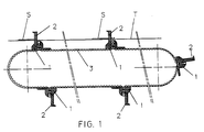
- the exemplary embodiment of the belt assembly shown in Fig. 1 comprises a finite belt 3 with a plurality of units 1 provided with carriers 2, these units being connected to the belt 3.
- the unit 1 shown at the right-hand side at the same time connects the two end parts of the finite belt 3.
- the belt 3 can also consist of several finite belts parts and that these are interconnected by several units of the type shown in one of Figs. 2-13. It will also be clear that the belt 3 can be an endless belt and that only units 1 of the type shown in Figs. 2-4 are mounted on the belt.
- the present invention also covers a finite belt with units mounted thereon.
- the units 1, 11 can be provided with carriers 2, 12, for conveying articles such as for instance items to be mailed on a transport track T, as well as with magnetic detection elements (not shown), for determining the position of the unit 1 or 11 in question or the belt assembly.
- the exemplary embodiment of unit 1 shown in Figs. 2-5 is intended both for attachment to a continuous belt part 3 (see Figs. 2-4) and to an interrupted belt part (Fig. 5).
- the unit 1 comprises a block-shaped body 4 having a passage 6 of a substantially rectangular cross-section, which extends from an underside 5 facing the belt 3, substantially perpendicularly to the underside 5, through the entire block-shaped body 4.
- the first sides 6a of the cross-section of the passage 6 extend perpendicularly to the direction of the path of the belt 3 and have a length substantially corresponding to the width of the belt 3.
- the second sides 6b of the cross-section of the passage 6 have a length such that two belt parts 3a, 3b having their toothed surfaces disposed against each other or a doubled belt part 3ab can be received between the first sides 6a.
- the unit 1 comprises means 7 for fixing the belt parts 3a, 3b having their toothed surfaces disposed against each other or a doubled belt part 3ab in the rectangular passage 6 using a fixing pin 9 serving as a retention element.
- the fixing pin 9 extends transversely to the main direction of the belt 3, parallel to the belt surface, between the belt parts having their toothed surfaces disposed against each other or between the legs 3b of a loop 3ab formed by the doubled belt part 3a.
- the means 7 for fixing the belt parts having their toothed surfaces disposed against each other or the doubled belt part 3ab using the fixing pin 9 are formed, in the embodiment shown, by two slots 7 which are provided in the respective passage walls corresponding with the second sides 6b of the cross-section.
- the slots 7 extend from an upper side 10 of the block-shaped body 4, substantially parallel to the passage 6 and terminate substantially halfway the passage 6 where the slots 7 form a supporting surface 7a for the fixing pin 9.
- the assembly of a unit 1 so designed is very simple. If the unit 1 is to be mounted on a continuous belt part, first the belt 3 is doubled at the point where the unit 1 is to be mounted. Then the loop 3ab formed by the doubled belt or, in the case of an interrupted belt, the two belt end parts 3a, 3b having their toothed surfaces positioned against each other, are slipped from the underside 5 of the unit through the passage 6 to such an extent that the fixing pin 9 can be fitted at the desired point between the legs 3b of the loop 3ab or between the belt end parts 3a, 3b situated against each other. Then the belt 3 and the loop 3ab formed thereby or the belt end parts 3a, 3b can be pulled down relative to the unit 1 until the fixing pin 9 abuts the supporting surfaces 7a of the slots 7.
- the fixing pin 9 could be accommodated in a bore (not shown) extending transversely to the direction of the path of the belt and intersecting the passage 6. This, however, renders assembly of the unit 1 more difficult because in that case the opening formed by the legs 3b of the belt loop 3ab or by the belt end parts 3a, 3b located against each other, must be brought into a position exactly in front of this bore before the fixing pin 9 can be introduced.
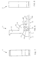
- Figs. 6-9 show an alternative unit 11 which at the same time serves for the connection of two belt end parts 13a and 13b, respectively.
- Such an alternative unit 11 is particularly suitable for forming an endless belt assembly from a finite belt assembly.
- the alternative unit 11 comprises a block-shaped body 14 having two channels 17 extending from an underside 15 facing the belt, substantially perpendicularly to this underside 15, in the direction of an upper side 16 of the block-shaped body 14.
- the channels 17 extend substantially transversely to the direction of the path of the belt 13 and are provided with a configuration such that these can receive the bent belt parts 13a, 13b so that the latter are form-closed.
- a tooth is missing in the substantially continuous toothed profile which is determined by the two belt parts 13 extending on either side of the unit 11.
- a depending central post 20 is provided, located between the channels 17, this central post 20 being provided at the lower end thereof with a tooth 21 of the same shape as the shape of the teeth of the belt parts 13.
- This tooth 21 replaces the missing tooth in the substantially continuous toothed profile of the belt, formed by the belt portions 13.
- the width of the block-shaped body 14 of the alternative unit 11 shown in Figs. 6-13 substantially corresponds to the width of the belt 13 and the channels 17 extend over the entire width of the block-shaped body 14.
- the belt end parts 13a and 13b can simply be slipped sideways into the channels 17.
- the central post 20 comprises tooth-shaped retention elements 19 connected integrally therewith.
- the carrier 2 and 12, respectively, and the block-shaped body 4 and 14, respectively, are integrally constructed.
- Such a unit 1 or 11 can be manufactured simply and at low cost price.
- the carrier 2 or 12 of the unit 1 or 11 is connected with block-shaped body 4 or 14 for pivotal motion about a line oriented perpendicularly to the direction of the path of the belt and parallel to the underside 5 or 15 of the unit 1 or 11, and is pretensioned into a vertical position by spring means 22, 23.
- the carrier 12 is connected with the block-shaped body 14 via a thin-walled part 24. Further, the carrier 12 is provided at the lower end thereof with a stop 25. In the vertical position of the carrier 12, the stop 25 rests against a counterstop 26 which is connected with the block-shaped body 14.
- the block-shaped body 14 and the carrier 12 are in this case made of a fibre-reinforced plastics, for instance.
- the carrier is not oriented entirely vertically, but has its upper side directed in the main direction. By arranging the counterstop 26, the carrier 12 is brought into the vertical position.
- the spring means are formed by the flexible part 22 which urges the carrier 12 into the vertical position but which permits the carrier to pivot about the connection 24 when greater forces are exerted on the carrier.
- Figs. 11 and 12 show another exemplary embodiment of a unit wherein the carrier 12 is pivotally connected to the block-shaped body 14 via a pivot pin 27.
- the spring means are formed by an O-ring 23 engaging around the lower end of the carrier 12 and the block-shaped body 14.
- all units 1 or 11 shown in Figs. 1-11 are provided, at any rate at a rear side 28 of the block-shaped body 4 or 14, with a supporting member 29 comprising a supporting surface 29a which extends from the block-shaped body 14 in the direction of the path of the belt and aligns with the underside 5 or 15 of the block-shaped body 4 or 14.
- a bolt, screw or similar connecting element 30 is arranged in the block-shaped body 14 and extends in the direction of the path of the belt 13 in such a manner that the two bent belt parts 13a, 13b are pierced and the channels 17 are squeezed together.
- a bolt, screw or similar connecting element 30 is arranged in the block-shaped body 14 and extends in the direction of the path of the belt 13 in such a manner that the two bent belt parts 13a, 13b are pierced and the channels 17 are squeezed together.
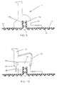
- Figs. 14 and 15 show a preferential exemplary embodiment of the invention.
- This embodiment relates to a unit 31 having a carrier 32 and a body 34. With the unit 31, end parts 33a of belts 33 can be connected to each other, as appears from Fig. 14.
- the unit 31 comprises channels 37 with open flanks having the end parts 33a of belts 33 clamped therein.
- the contours 40, against which rest the belt end parts 33a, are bent to such an extent as to have portions 40a directed in mutually opposite directions.
- the belt end parts 33a in the channels 37 are bent to a corresponding extent, so that the ends thereof also point in mutually opposite directions.
- the unit 31 projects only over a slight distance relative to the path determined by the belt parts 33.
- the end parts 33a can simply be slipped sideways through the open flanks of the channels 37 into the unit 31 and be clamped, whereupon they are confined and restrained from displacement in longitudinal direction owing to the retention elements constructed as teeth 39. Being clamped in the channels 37, the belt parts 33a are restrained from lateral displacement.
- a central part 42 which is clamped tightly between teeth of the two belt end parts 33a, also contributes to the retention of the belt portions 33 in both lateral and longitudinal directions, an accurate positioning being obtained in particular in longitudinal direction. This last, in turn, is important to obtain a continuous row of teeth along the toothed surfaces 38 of the belt portions 33, the pitch between teeth of one belt portion 33 and the other belt portion 33 always being a whole multiple of the pitch between successive teeth of each belt portion.
- the oppositely directed course of the end parts 33a of the belt parts 33 is moreover advantageous because at a given belt tension the bending moment exerted on the parts of the unit that determine the contours 40 is considerably smaller than in the case where the end parts extend perpendicularly to the path determined by the belt parts 33 and form arms extending transversely to the direction of tension.
- the unit 31 according to Figs. 14 and 15 can be simply manufactured by injection-moulding from plastics.
- the body 34 of the unit comprises a stiffening rib 43 extending about the channel 37.
- the unit 31 further comprises a carrier in the form of a finger 32, integrally formed thereon.
- a carrier in the form of a finger 32, integrally formed thereon.
- the unit 31 is provided on one side 28 with a supporting member 49 having a supporting surface 49a extending in the direction of path of the belt and against which the back side of the belt 33 abuts when the portions thereof that are adjacent to the unit 31 on either side thereof are tensioned in a straight path.
- the contours 40 and the end parts 33a of the belt parts 33 may also have configurations that diverge relatively to each other, away from the path determined by the belt portions. In that case, too, compared with an embodiment where the contours and the belt portions are directed perpendicularly to the path determined by the belt portions, a flatter construction of the unit and a reduction of the bending moments exerted on the parts of the unit that carry the contours 40. However, the effect achieved is then smaller than in the case of the embodiment of the invention shown in Figs. 14 and 15.
Landscapes
- Engineering & Computer Science (AREA)
- Mechanical Engineering (AREA)
- General Engineering & Computer Science (AREA)
- Belt Conveyors (AREA)
- Devices For Conveying Motion By Means Of Endless Flexible Members (AREA)
Claims (17)
- Bandzusammenbau, der sich in gespanntem Zustand entlang einer Bahn erstreckt, mit einem Band (3, 13, 33), das eine gezahnte Oberseite (8, 18, 38) und eine gegenüberliegend angeordnete Rückenseite und zumindest eine Einheit (1, 11, 31) aufweist, die an dem Band in einer Position auf der Seite der Rückenseite befestigt ist, wobeiin dem Bereich der Einheit (1, 11, 31) Abschnitte (3a, 3b, 13a, 13b, 33a) des Bandes (3, 13, 33) aus der Bahn des Bandzusammenbaus in Richtung der Einheit (1, 11, 31) herausgebogen sind, unddie Einheit (1, 11, 31) zumindest ein Rückhalteelement (9, 19, 39) im Eingriff mit den gezahnten Oberseiten (8, 18, 38) der gebogenen Bandabschnitte (3a, 3b, 13a, 13b, 33a), Auflagekonturen, an denen die Rückenseiten der gebogenen Bandabschnitte anlegen, und einen Verbindungsabschnitt, der die Auflagekonturen miteinander verbindet, um zumindest einen Durchgang oder Kanal zur Aufnahme der gebogenen Bandabschnitte bereitzustellen, aufweist, wobei der Verbindungsabschnitt das bzw. die Rückhalteelement/e trägt.
- Bandzusammenbau gemäß Anspruch 1, bei dem die Position des oder jedes Rückhalteelementes (9, 19, 39) sowie die Form der Auflagekonturen der Bereiche der Einheit (1, 11, 31), an denen die Rückenseiten der gebogenen Bandabschnitte (3a, 13a, 13b, 33a) anliegen, so geartet sind, daß die Zähne der Abschnitte des gezahnten Bandes, die an die Einheit (1, 11, 31) anstoßen, auf jeder ihrer Seiten ein gezahntes Profil definieren, das sich über beide Bandabschnitte erstreckt, wobei der Abstand zwischen den Zähnen des Bandabschnittes auf einer Seite der Einheit und den Zähnen des Bandabschnittes auf der anderen Seite der Einheit ein ganzes Vielfaches des Abstandes aufeinanderfolgender Zähne eines jeden der Bandabschnitte ist.
- Bandzusammenbau gemäß Anspruch 2, bei dem die Konturen der Teile der Einheit (1, 11, 31), an denen die Rückenseiten der gebogenen Bandabschnitte (3a, 3b, 13a, 13b, 33a) anliegen, außerdem derart gestaltet sind, daß der Abstand zwischen Zähnen des Bandabschnittes auf einer Seite der Einheit und Zähnen des Bandabschnittes auf der anderen Seite der Einheit auch ein ganzes Vielfaches des Abstandes von aufeinanderfolgenden Zähnen eines jeden der Bandabschnitte ist, wenn sich die Bandabschnitte entlang einer Bahn erstrecken, die in solcher Weise gebogen ist, daß die gezahnte Seite des Bandes auf der Innenseite angeordnet ist.
- Bandzusammenbau gemäß einem der vorherigen Ansprüche, bei dem das gezahnte Band unterbrochen ist und Bandendabschnitte (13a, 13b, 33a) auf gegenüberliegenden Seiten der Unterbrechung die gebogenen Bandabschnitte bilden.
- Bandzusammenbau gemäß Anspruch 4, bei dem die Bandendabschnitte (33a) relativ zueinander in die Richtung ihrer Enden auseinandergehen.
- Bandzusammenbau gemäß Anspruch 4 oder 5, bei dem sich die Bandendabschnitte (33a) in entgegengesetzte Richtungen erstrecken.
- Bandzusammenbau gemäß einem der Ansprüche 4 bis 6, bei dem die oder jede Einheit (1, 11, 31) Kanäle (17, 37) zur Aufnahme von Bandendabschnitten (13a, 13b, 33a) aufweist, wobei die Kanäle mit offenen Flanken ausgestattet sind, die den gebogenen Bandendabschnitten (13a, 13b, 33a) ermöglichen, seitlich in und aus den beiden Flanken der Einheit (1, 11, 31) geschoben zu werden.
- Bandzusammenbau gemäß einem der Ansprüche 1 bis 3, bei dem die oder jede Einheit (1) einen blockförmigen Körper (4) aufweist, der einen Durchgang (6) mit einem im wesentlichen rechteckigen Querschnitt hat, wobei sich der Durchgang (6) von einer dem Band (3) zugewandten Unterseite (5) im wesentlichen senkrecht zu der Unterseite (5) durch den gesamten blockförmigen Körper (4) erstreckt, wobei sich erste Seiten (6a) des Querschnitts senkrecht zu der Richtung der Bahn des Bandes (3) erstrecken und eine im wesentlichen der Breite des Bandes (3) entsprechende Länge haben, während zwei mit ihren gezahnten Oberseiten (8) gegeneinander angeordnete Bandabschnitte (3a, 3b) oder ein doppelter Bandabschnitt (3ab) zwischen den ersten Seiten (6a) aufgenommen werden, wobei die oder jede Einheit Mittel (7) zur Befestigung der mit ihren gezahnten Oberseiten (8) gegeneinander angeordneten Bandabschnitte (3a, 3b) oder eines doppelten Bandabschnittes (3ab) in dem rechteckigen Durchgang (6) aufweisen, die einen Befestigungsstift (9) beinhalten, der als Rückhalteelement dient, wobei sich der Befestigungsstift (9) quer zu der Richtung der Bahn des Bandzusammenbaus parallel zu einer Bandfläche zwischen den Bandabschnitten erstreckt, deren gezahnte Oberseiten einander zugewandt oder zwischen den Schenkeln (3b) einer Schleife (3ab), die von dem doppelten Bandabschnitt gebildet ist, liegen.
- Bandzusammenbau gemäß einem der Ansprüche 1 bis 7, bei dem die oder jede Einheit (11, 31) zwei Kanäle (17, 37), die sich von einer dem Band (13, 33) zugewandten Unterseite (15) erstecken, und Rückhaltelelemente (19, 39), die in die Kanäle vorspringen, aufweist, wobei die gebogenen Bandabschnitte (13a, 13b, 33a) derart in den Kanälen aufgenommen werden, daß sie in Längsrichtung formschlüssig sind.
- Bandzusammenbau gemäß Anspruch 9, bei dem ein mittiger Halter (20) zwischen den Kanälen (17) mit einem Ende versehen ist, das über die Unterseite der oder jeder Einheit (11) hinaus vorspringt, wobei das Ende als ein Zahn (21) mit derselben Form wie die Zähne des Bandes (13) gestaltet ist.
- Bandzusammenbau gemäß Anspruch 8, bei dem die Mittel zur Befestigung der mit ihren gezahnten Oberseiten gegeneinander angeordneten Bandabschnitte (3b) oder des doppelten Bandabschnittes (3ab) in dem rechteckigen Durchgang (6) außer dem Befestigungsstift (9) zwei Schlitze (7) beinhalten, die in den jeweiligen Durchgangswänden entsprechend den zweiten Seiten (6b) des Querschnitts angeordnet sind, wobei sich die Schlitze (7) von einer Oberseite (10) des blockförmigen Körpers (4) im wesentlichen parallel zu dem Durchgang (6) erstrecken und im wesentlichen auf der Hälfte des Durchgangs (6) enden, wo die Schlitze (7) eine Tragfläche (7a) für den Befestigungsstift (9) bilden.
- Bandzusammenbau gemäß einem der vorherigen Ansprüche, bei dem die oder jede Einheit (1, 11, 31) einen Mitnehmer (2, 12, 32) aufweist.
- Bandzusammenbau gemäß Anspruch 12, bei dem der Mitnehmer (2, 12, 32) einen integrierten Teil der Einheit (1, 11, 31) bildet.
- Bandzusammenbau gemäß Anspruch 12, bei dem der Mitnehmer (12) schwenkbeweglich um eine Linie, die senkrecht zu der Richtung der Bahn des Bandzusammenbaus und parallel zu der Unterseite (15) der Einheit (11) ausgerichtet ist, angebracht ist und durch Federelemente (22 bzw. 23) in einer von der Bahn vorspringenden Position vorgespannt wird.
- Bandzusammenbau gemäß einem der Ansprüche 12 bis 14, bei dem die oder jede Einheit zumindest auf einer Seite (28) mit einem Tragelelement (29, 49) mit einer Tragfläche (29a, 49a) ausgestattet ist, die sich in die Richtung der Bahn des Bandzusammenbaus erstreckt, und an der die Rückenseite des Bandes (3, 13, 33) anliegt, wenn die an die Einheit (1, 11, 31) auf deren beiden Seiten anstoßenden Abschnitte des Bandes entlang einer geraden Bahn gespannt sind.
- Bandzusammenabu gemäß einem der vorherigen Ansprüche, bei dem die oder jede Einheit (1, 11, 31) ein magnetisches Erfassungselement aufweist.
- Einheit zur Verbindung der gezahnten Bandabschnitte mitgegenüberliegend angeordneten Auflagekonturen für Auflageabschnitte (3a, 3b, 13a, 13b, 33a) eines gezahnten Bandes, die aus einer Bahn, entlang welcher das Band gespannt ist, herausgebogen sind,zumindest einem Rückhaltelement (9, 19, 39), das zumindest einer der Auflagekonturen gegenüberliegend angeordnet und für den Eingriff mit den gezahnten Oberseiten (8, 18, 38) der gebogenenen Bandabschnitte (3a, 13a, 13b, 33a) eingerichtet ist, undeinem Verbindungsabschnitt (4, 14, 34), der die Auflagekonturen miteinander verbindet und sich über zumindest einen Durchgang (6) oder Kanal (17, 37) erstreckt, um die gebogenen Bandabschnitte (3a, 13a, 13b, 33a) aufzunehmen und das oder die Rückhalteelement/e (9, 19, 39) zu tragen.
Applications Claiming Priority (2)
| Application Number | Priority Date | Filing Date | Title |
|---|---|---|---|
| NL9200915 | 1992-05-22 | ||
| NL9200915A NL9200915A (nl) | 1992-05-22 | 1992-05-22 | Riemsamenstel. |
Publications (2)
| Publication Number | Publication Date |
|---|---|
| EP0571048A1 EP0571048A1 (de) | 1993-11-24 |
| EP0571048B1 true EP0571048B1 (de) | 1997-12-10 |
Family
ID=19860837
Family Applications (1)
| Application Number | Title | Priority Date | Filing Date |
|---|---|---|---|
| EP93201452A Expired - Lifetime EP0571048B1 (de) | 1992-05-22 | 1993-05-19 | Zusammenbau eines Bandes |
Country Status (4)
| Country | Link |
|---|---|
| US (2) | US5979639A (de) |
| EP (1) | EP0571048B1 (de) |
| DE (1) | DE69315617T2 (de) |
| NL (1) | NL9200915A (de) |
Families Citing this family (26)
| Publication number | Priority date | Publication date | Assignee | Title |
|---|---|---|---|---|
| NL9200915A (nl) * | 1992-05-22 | 1993-12-16 | Hadewe Bv | Riemsamenstel. |
| US7008341B2 (en) * | 2001-06-27 | 2006-03-07 | The Goodyear Tire & Rubber Company | Reduced noise multi-ribbed power transmission belt |
| DE20207499U1 (de) * | 2002-05-14 | 2002-08-14 | Transnorm System GmbH, 31177 Harsum | Umlaufender Mitnehmer |
| US6935488B2 (en) * | 2003-03-31 | 2005-08-30 | Oxbo International Corporation | Blade pulley |
| US7070042B2 (en) * | 2003-03-31 | 2006-07-04 | Oxbo International Corporation | Blade pulley |
| US6949211B2 (en) | 2003-04-16 | 2005-09-27 | The Goodyear & Rubber Company | Means of manufacturing plural optimized cogged drive belts |
| US7237669B2 (en) * | 2004-04-22 | 2007-07-03 | Serpentix Conveyor Corp. | Clip for assemblage by clamps |
| EP1614731B1 (de) * | 2004-07-05 | 2008-08-27 | 3M Innovative Properties Company | Grundierung aus PTFE für Metallsubstrate |
| WO2006022332A1 (ja) * | 2004-08-26 | 2006-03-02 | Nitta Corporation | ベルトの継手加工方法、プリセッターおよび継手加工装置 |
| US8257463B2 (en) * | 2006-01-23 | 2012-09-04 | Avx Corporation | Capacitor anode formed from flake powder |
| US7810219B2 (en) * | 2006-09-08 | 2010-10-12 | Designatronics, Inc. | Clamp for timing belt |
| ITBO20070640A1 (it) * | 2007-09-24 | 2009-03-25 | Vision Tech S R L | Metodo per realizzare una cinghia ad anello chiuso per organo trasportatore e cinghia cosi' ottenuta |
| US7690500B2 (en) * | 2008-01-31 | 2010-04-06 | Deere & Company | Hybrid draper belt splice |
| US8066116B2 (en) * | 2008-02-18 | 2011-11-29 | Mato Maschinen-Und Metallwarenfabrik Curt Matthaei Gmbh & Co. Kg | Conveyor belt end connection |
| US8590113B2 (en) * | 2010-05-26 | 2013-11-26 | Massachusetts Institute Of Technology | Methods and apparatus for applying tension to a motion transmission element |
| JP5870331B2 (ja) * | 2012-01-25 | 2016-02-24 | 旭精工株式会社 | 物搬送ベルト及び硬貨選別装置 |
| DE102014014649A1 (de) * | 2014-10-08 | 2016-04-28 | CU4innovation GmbH | Vorrichtung zum Befestigen eines Objekts an einem Zahnriemen |
| JP6517125B2 (ja) * | 2014-10-31 | 2019-05-22 | 三ツ星ベルト株式会社 | 平ベルト、ベルト機構、ベルト昇降機構、取付方法、及び、平ベルトの製造方法 |
| WO2016068296A1 (ja) * | 2014-10-31 | 2016-05-06 | 三ツ星ベルト株式会社 | 平ベルト、ベルト機構、ベルト昇降機構、取付方法、及び、平ベルトの製造方法 |
| DE202015100657U1 (de) * | 2015-02-11 | 2015-02-23 | Gerhard Schubert Gmbh | Zufuhrketten-Einheit |
| EP3056441B1 (de) * | 2015-02-11 | 2017-05-10 | Gerhard Schubert GmbH | Schlauchbeutelmaschine und verfahren zu ihrem betrieb |
| CN105173530A (zh) * | 2015-09-28 | 2015-12-23 | 京东方科技集团股份有限公司 | 传送带连接装置及传送带驱动装置 |
| KR101754628B1 (ko) * | 2016-01-06 | 2017-07-06 | (주)제이티 | 이송툴 |
| US10589152B2 (en) * | 2016-03-18 | 2020-03-17 | Sure Win, Llc | Apparatus for collecting and storing tennis balls |
| JP6824102B2 (ja) * | 2017-04-24 | 2021-02-03 | 株式会社ミツトヨ | ベルト駆動による軸方向移動装置 |
| DE102021124682B4 (de) | 2021-09-23 | 2026-04-23 | G. Kraft Maschinenbau Gesellschaft mit beschränkter Haftung | Zahnriemenschloss sowie Heizpresse mit einem Zahnriemenantrieb |
Family Cites Families (14)
| Publication number | Priority date | Publication date | Assignee | Title |
|---|---|---|---|---|
| DE114719C (de) * | ||||
| FR373712A (fr) * | 1907-01-19 | 1907-05-25 | Aubert Et Bouvard Soc | Agrafe à serrage excentrique pour assemblage de courroies |
| DE803689C (de) * | 1948-10-02 | 1951-04-09 | Eisengiesserei U Maschinenfabr | Keilriemenverbindung |
| US2687209A (en) * | 1949-10-27 | 1954-08-24 | Rost Helge Fabian | Endless conveyer or elevator belt and resilient joint for same |
| US3015381A (en) * | 1957-02-14 | 1962-01-02 | Mohwinkel | Belt conveyors |
| GB1053764A (de) * | 1963-04-04 | |||
| US3590737A (en) * | 1968-07-23 | 1971-07-06 | Cameron Machine Co | Printing machine belt assembly |
| FR2370652A1 (fr) * | 1976-11-10 | 1978-06-09 | Metraplan Spa | Systeme de fixation d'elements sur bandes et tapis transporteurs |
| US4348947A (en) * | 1981-01-21 | 1982-09-14 | Luftek, Inc. | Self-cleaning chimney stack |
| FR2589550B1 (fr) * | 1985-10-30 | 1987-12-24 | Caoutchouc Manuf Plastique | Dispositif d'agrafage pour la jonction des courroies, procede de jonctionnement utilisant ce dispositif et courroie jonctionnee selon ce procede |
| US4884393B1 (en) * | 1987-12-23 | 1995-03-14 | Hilleby International Inc | Conveyor system for use particularly with harvesters |
| US4993995A (en) * | 1988-10-29 | 1991-02-19 | Mita Industrial Co., Ltd. | Toothed-belt fixing mechanism |
| SU1668225A1 (ru) * | 1988-12-20 | 1991-08-07 | Опытно-Конструкторское Бюро Всесоюзного Научно-Исследовательского Института Гидротехники И Мелиорации Им.А.Н.Костякова С Опытным Производством | Устройство дл стыковки резинотросовой ленты |
| NL9200915A (nl) * | 1992-05-22 | 1993-12-16 | Hadewe Bv | Riemsamenstel. |
-
1992
- 1992-05-22 NL NL9200915A patent/NL9200915A/nl not_active Application Discontinuation
-
1993
- 1993-05-19 DE DE69315617T patent/DE69315617T2/de not_active Expired - Fee Related
- 1993-05-19 EP EP93201452A patent/EP0571048B1/de not_active Expired - Lifetime
- 1993-05-21 US US08/064,440 patent/US5979639A/en not_active Expired - Fee Related
-
1999
- 1999-01-25 US US09/236,460 patent/US6216849B1/en not_active Expired - Lifetime
Also Published As
| Publication number | Publication date |
|---|---|
| US6216849B1 (en) | 2001-04-17 |
| DE69315617D1 (de) | 1998-01-22 |
| NL9200915A (nl) | 1993-12-16 |
| DE69315617T2 (de) | 1998-04-02 |
| EP0571048A1 (de) | 1993-11-24 |
| US5979639A (en) | 1999-11-09 |
Similar Documents
| Publication | Publication Date | Title |
|---|---|---|
| EP0571048B1 (de) | Zusammenbau eines Bandes | |
| KR101508897B1 (ko) | 분리 가능하게 고정된 보강 링크를 갖는 모듈형 벨트 링크 | |
| US5004097A (en) | Replaceable snap-on modular overlay for rod and link turn-curve conveyor belts | |
| US5069330A (en) | Side plate for a plastic spiral conveyor belt system | |
| US8770379B2 (en) | Sorting device | |
| EP1422171B1 (de) | Kettenfördervorrichtung mit kreuzung | |
| US20050211532A1 (en) | Belt attachment device and method | |
| HU183982B (en) | Konveyor | |
| KR101804010B1 (ko) | 복합 링크를 갖는 컨베이어 벨트 | |
| US20070161443A1 (en) | Wear resistant split sprocket for modular link belt systems | |
| US5219065A (en) | Chain link for a product capturing chain | |
| AU3059699A (en) | Conveyor mat | |
| EP0724537A1 (de) | Transportvorrichtung, verfahren und anlage zum herstellen von transportvorrichtungen | |
| JPH11246019A (ja) | 搬送用歯付ベルト及び、歯付ベルト用被覆除去治具 | |
| EP2332862B1 (de) | Pratze zum Einstellen der Gurtspannung eines Förderers | |
| EP0446587A1 (de) | Träger für Vorhänge, insbesondere für regulierbare Jalousien | |
| US5369833A (en) | Offset sidebar flight supporting chain | |
| EP0524543A1 (de) | Verteil-Transportvorrichtung | |
| GB2134477A (en) | Single-chain or multiple-chain conveyor | |
| US4939978A (en) | Ammunition chuting for a machine gun | |
| US10850925B2 (en) | Chain for vacuum conveyor | |
| SU1729961A1 (ru) | Двухшарнирна пластинчата цепь дл конвейеров | |
| GB2125755A (en) | Attaching propelling means to conveyor chains | |
| HK1123265B (en) | Modular belt link having a detachably fixed reinforcement link |
Legal Events
| Date | Code | Title | Description |
|---|---|---|---|
| PUAI | Public reference made under article 153(3) epc to a published international application that has entered the european phase |
Free format text: ORIGINAL CODE: 0009012 |
|
| AK | Designated contracting states |
Kind code of ref document: A1 Designated state(s): DE FR GB NL |
|
| 17P | Request for examination filed |
Effective date: 19940113 |
|
| 17Q | First examination report despatched |
Effective date: 19950324 |
|
| GRAG | Despatch of communication of intention to grant |
Free format text: ORIGINAL CODE: EPIDOS AGRA |
|
| GRAG | Despatch of communication of intention to grant |
Free format text: ORIGINAL CODE: EPIDOS AGRA |
|
| GRAH | Despatch of communication of intention to grant a patent |
Free format text: ORIGINAL CODE: EPIDOS IGRA |
|
| GRAH | Despatch of communication of intention to grant a patent |
Free format text: ORIGINAL CODE: EPIDOS IGRA |
|
| GRAA | (expected) grant |
Free format text: ORIGINAL CODE: 0009210 |
|
| AK | Designated contracting states |
Kind code of ref document: B1 Designated state(s): DE FR GB NL |
|
| PG25 | Lapsed in a contracting state [announced via postgrant information from national office to epo] |
Ref country code: NL Free format text: LAPSE BECAUSE OF FAILURE TO SUBMIT A TRANSLATION OF THE DESCRIPTION OR TO PAY THE FEE WITHIN THE PRESCRIBED TIME-LIMIT Effective date: 19971210 |
|
| REF | Corresponds to: |
Ref document number: 69315617 Country of ref document: DE Date of ref document: 19980122 |
|
| ET | Fr: translation filed | ||
| NLV1 | Nl: lapsed or annulled due to failure to fulfill the requirements of art. 29p and 29m of the patents act | ||
| PLBE | No opposition filed within time limit |
Free format text: ORIGINAL CODE: 0009261 |
|
| STAA | Information on the status of an ep patent application or granted ep patent |
Free format text: STATUS: NO OPPOSITION FILED WITHIN TIME LIMIT |
|
| 26N | No opposition filed | ||
| REG | Reference to a national code |
Ref country code: GB Ref legal event code: IF02 |
|
| PGFP | Annual fee paid to national office [announced via postgrant information from national office to epo] |
Ref country code: FR Payment date: 20090513 Year of fee payment: 17 Ref country code: DE Payment date: 20090525 Year of fee payment: 17 |
|
| PGFP | Annual fee paid to national office [announced via postgrant information from national office to epo] |
Ref country code: GB Payment date: 20090522 Year of fee payment: 17 |
|
| GBPC | Gb: european patent ceased through non-payment of renewal fee |
Effective date: 20100519 |
|
| REG | Reference to a national code |
Ref country code: FR Ref legal event code: ST Effective date: 20110131 |
|
| PG25 | Lapsed in a contracting state [announced via postgrant information from national office to epo] |
Ref country code: DE Free format text: LAPSE BECAUSE OF NON-PAYMENT OF DUE FEES Effective date: 20101201 |
|
| PG25 | Lapsed in a contracting state [announced via postgrant information from national office to epo] |
Ref country code: FR Free format text: LAPSE BECAUSE OF NON-PAYMENT OF DUE FEES Effective date: 20100531 |
|
| PG25 | Lapsed in a contracting state [announced via postgrant information from national office to epo] |
Ref country code: GB Free format text: LAPSE BECAUSE OF NON-PAYMENT OF DUE FEES Effective date: 20100519 |