EP0569918B1 - Kabelzugentlastungsvorrichtung für elektrischen abgeschirmten Verbinder - Google Patents
Kabelzugentlastungsvorrichtung für elektrischen abgeschirmten Verbinder Download PDFInfo
- Publication number
- EP0569918B1 EP0569918B1 EP93107592A EP93107592A EP0569918B1 EP 0569918 B1 EP0569918 B1 EP 0569918B1 EP 93107592 A EP93107592 A EP 93107592A EP 93107592 A EP93107592 A EP 93107592A EP 0569918 B1 EP0569918 B1 EP 0569918B1
- Authority
- EP
- European Patent Office
- Prior art keywords
- connector
- tab
- clip
- cable
- drain wire
- Prior art date
- Legal status (The legal status is an assumption and is not a legal conclusion. Google has not performed a legal analysis and makes no representation as to the accuracy of the status listed.)
- Expired - Lifetime
Links
Images


Classifications
-
- H—ELECTRICITY
- H01—ELECTRIC ELEMENTS
- H01R—ELECTRICALLY-CONDUCTIVE CONNECTIONS; STRUCTURAL ASSOCIATIONS OF A PLURALITY OF MUTUALLY-INSULATED ELECTRICAL CONNECTING ELEMENTS; COUPLING DEVICES; CURRENT COLLECTORS
- H01R9/00—Structural associations of a plurality of mutually-insulated electrical connecting elements, e.g. terminal strips or terminal blocks; Terminals or binding posts mounted upon a base or in a case; Bases therefor
- H01R9/03—Connectors arranged to contact a plurality of the conductors of a multiconductor cable, e.g. tapping connections
- H01R9/05—Connectors arranged to contact a plurality of the conductors of a multiconductor cable, e.g. tapping connections for coaxial cables
- H01R9/0524—Connection to outer conductor by action of a clamping member, e.g. screw fastening means
-
- H—ELECTRICITY
- H01—ELECTRIC ELEMENTS
- H01R—ELECTRICALLY-CONDUCTIVE CONNECTIONS; STRUCTURAL ASSOCIATIONS OF A PLURALITY OF MUTUALLY-INSULATED ELECTRICAL CONNECTING ELEMENTS; COUPLING DEVICES; CURRENT COLLECTORS
- H01R13/00—Details of coupling devices of the kinds covered by groups H01R12/70 or H01R24/00 - H01R33/00
- H01R13/648—Protective earth or shield arrangements on coupling devices, e.g. anti-static shielding
- H01R13/658—High frequency shielding arrangements, e.g. against EMI [Electro-Magnetic Interference] or EMP [Electro-Magnetic Pulse]
- H01R13/6591—Specific features or arrangements of connection of shield to conductive members
- H01R13/65912—Specific features or arrangements of connection of shield to conductive members for shielded multiconductor cable
- H01R13/65914—Connection of shield to additional grounding conductors
-
- H—ELECTRICITY
- H01—ELECTRIC ELEMENTS
- H01R—ELECTRICALLY-CONDUCTIVE CONNECTIONS; STRUCTURAL ASSOCIATIONS OF A PLURALITY OF MUTUALLY-INSULATED ELECTRICAL CONNECTING ELEMENTS; COUPLING DEVICES; CURRENT COLLECTORS
- H01R13/00—Details of coupling devices of the kinds covered by groups H01R12/70 or H01R24/00 - H01R33/00
- H01R13/58—Means for relieving strain on wire connection, e.g. cord grip, for avoiding loosening of connections between wires and terminals within a coupling device terminating a cable
-
- H—ELECTRICITY
- H01—ELECTRIC ELEMENTS
- H01R—ELECTRICALLY-CONDUCTIVE CONNECTIONS; STRUCTURAL ASSOCIATIONS OF A PLURALITY OF MUTUALLY-INSULATED ELECTRICAL CONNECTING ELEMENTS; COUPLING DEVICES; CURRENT COLLECTORS
- H01R24/00—Two-part coupling devices, or either of their cooperating parts, characterised by their overall structure
- H01R24/60—Contacts spaced along planar side wall transverse to longitudinal axis of engagement
- H01R24/62—Sliding engagements with one side only, e.g. modular jack coupling devices
Definitions
- This invention relates to an electrical connector according to the preamble of claim 1 and to a one piece metal shield according to the preamble of claim 8.
- the invention is concerned with the provision of cable strain relief in a shielded electrical connector for terminating electrical cables having drain wires. It relates to a metal shield adapted to provide for cable strain relief and to an electrical connector provided with such a shield. Where signal wires of a shielded electrical cable have been terminated to electrical terminals of an electrical connector, it is desirable that the electrical connections between the signal wires and the terminal should be protected against accidental tensioning of the cable.
- the electrical connector of the above construction has the following advantages.
- the known electrical connector provides in a basic way for shielding of the components and some support for the electrical cable through the cable clamping rib.
- the document GB-A-564 419 discloses an electrical connector including a plate of insulating material around which the cable of the connector may be wound in order to provide strain relief.
- the instant invention overcomes the above-mentioned problems.
- the present invention is intended to provide, in an electrical connector, strain relief for the signal wires of a shielded electrical cable which has been terminated to the connector, by cooperation between a drain wire of the cable and metal shielding of the connector.
- the connector terminating signal wires of a shielded electrical cable having a drain wire
- the connector comprising an insulating housing containing electrical terminals having contacts electrically connected to signal wires of the electrical cable and metal shielding covering at least a part of the insulating housing; a grounding clip connected to the metal shielding receives an end part of the cable from which the signal wires extend to contacts of the connector, the drain wire of the cable being wound in a circuitous part about the grounding clip thereby to provide strain relief for the electrical connections between the contacts of the terminals and the signal wires of the cable.
- the metal shield for the housing may be stamped and formed from a single piece of sheet metal stock so as to include the grounding clip.
- the grounding clip is provided with a plurality of pairs of opposed notches, for receiving the drain wire and thereby ensuring that it cannot slip from the grounding clip.
- a length of insulative tape may be wound about the grounding clip. The whole of the drain wire projecting from the cable end portion should be wound about the grounding clip, preferably so as to assume a figure of eight configuration.
- the notches are preferably formed in opposite edges of tabs projecting from cable embracing arms of the grounding clip, beyond the cable end portion when it is received in the grounding clip.
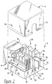
- a shielded, panel mount electrical jack comprises a partially shielded jack connector 4 and a main metal shield 6.
- the connector 4 comprises a one piece insulating housing 8 having a wire connecting rear part 10 and a mating, forward jack part 12.
- the lower part and the base of the wire connecting part 10 are surrounded by a one piece metal shield 14, the jack part 12 being surrounded by a one piece metal shield 16 which is open forwardly.
- a panel engaging member 18 of the jack part 12 projects through the upper wall of the shield 16, and panel engaging latch arms 20, only one of which is shown, project forwardly from the wire connecting part 10 beneath the jack part 12, the shield 16 having rearwardly projecting panel engaging tabs 22, only one of which is shown.
- the shield 14 which is in the form of a tray, has side walls 24 with peened over tabs 26, only one of which is shown, securing the shield 14 to the housing 8.
- the side walls 24 are spanned by a rear wall 28 of the shield 14.
- Latching tabs 30 are provided on the walls 24 and 28 for cooperation with latching openings 32 in the main shield 6 for securing it to the connector 4.
- the wire connecting part 10 of the housing 8 comprises pair of opposed, parallel wire combs 34 upstanding from the base of the housing part 10 and defining between them a channel 36.
- Each comb 34 has five teeth 38 and between the teeth 38 of each adjacent pair of teeth, an insulation displacement, slotted plate contact 40 (Figure 13) of an electrical terminal having a mating contact spring 42 ( Figure 1) projecting obliquely upwardly into a forward opening 44 of the housing part 12, for receiving a mating, shielded electrical plug (not shown) having contacts for engaging the respective contact springs 42.
- the housing 8 has an outer wire supporting ledge 43 extending longitudinally of the comb 34.
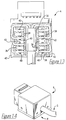
- a grounding clip formed integrally with the rear wall 28 of the shield 14 of the housing part 10, comprises a substantially U-shaped clip portion 48 having a base 50 from opposite edges of which project rearwardly, opposed clip arms 52.
- Each arm 52 has a forward planar part 54 connected to the base 50, an intermediate planar part 56 connected to the part 54 and being angled slightly inwardly with respect thereto and a rearward tab 58 connected to the part 56 and being angled slightly outwardly with respect thereto, so that the tabs 58 co-operate to define a rearwardly flared, cable guiding mouth.
- Each tab 58 has formed in its upper and lower edges, respectively, upper and lower, opposed, drain wiring receiving notches 60, as best seen in Figures 8 and 9.
- Each notch 60 is disposed proximate to the free end of the respective arm 52.
- the base 50 of each clip portion 48 is connected to the wall of the shield 14, by means of a flexible, rectilinear strap 62 coplanar with the wall 28 and upstanding from the bottom of a notch 64 in the wall 28.
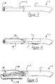
- the part of the cable C proximate to the exposed signal wires SW is inserted between the arms 52 of the clip portion 48 of the cable clip 46, guided by the mouth provided by the tabs 58.
- the jacket J is gripped between the clip arms 52, the drain wire DW being nearest to the base 50 of the clip portion 48.
- the clip portion 48 is then closed by grasping the tabs 58 between the jaws of a pair of needle point pliers P as shown in Figure 7.
- the tabs 58 may, however, be gripped between the fingers for the purpose of closing the clip portion 48.
- the closing of the clip portion 48 is facilitated, because the parts 56 of the arms 52 are easily bent inwards about their junctions with the parts 54 as will be apparent from Figures 8 and 9, the tabs 58 being easily bent inwards about their junctions with the parts 56 of the arms 52.
- the drain wire DW is laced through the lower notch 60 of one of the tabs 58 and the upper notch 60 of the other tab 58 as shown in Figure 8, and the drain wire, which is, of course, stiffly flexible, is wound about the tabs 58 as shown in Figure 9, to follow a circuitous path.
- the drain wire DW is led down externally of the other tab 58, is passed through a lower notch 60 thereof, and up between the tabs 58 through the upper notch 60 of the one tab 58 and is led down externally of that tab and through the lower notch 60 thereof, as shown in Figure 9, the free end of the drain wire DW being left between the tabs 58, whereby the drain wire DW has a figure of eight configuration.
- the whole of the drain wire DW should be wrapped about the tabs 58, the free end of the wire DW being finally disposed therebetween.
- the connector 4, when so wired, may be used simply as a grounded connector, or the main shield 6 may be secured thereto as shown in Figure 14 for the connector 4 to be used as a fully shielded connector.
- the drain wire DW affords strain relief for the electrical connections between the wires SW and the contacts 40, should the cable C be inadvertently tensioned, no other strain relief means being required.
- the shield 14 can readily be stamped and formed from a single piece of sheet metal so as to include the grounding clip 46.
Landscapes
- Details Of Connecting Devices For Male And Female Coupling (AREA)
- Coupling Device And Connection With Printed Circuit (AREA)
Claims (10)
- Elektrischer Verbinder (4) für den Anschluß von Signaldrähten (SW) eines abgeschirmten elektrischen Kabels (C), das einen Ableitdraht (DW) aufweist, wobei der Verbinder (4) ein isolierendes Gehäuse (8) besitzt, das elektrische Anschlüsse (40, 42) mit Kontakten (40) enthält, die mit den Signaldrähten (SW) des abgeschirmten elektrischen Kabels (C) elektrisch verbunden sind, und wobei eine Metallabschirmung (14) wenigstens einen Teil des isolierenden Gehäuses (8) bedeckt,
dadurch gekennzeichnet, daß eine Erdungsklammer (46) mit der Metallabschirmung (14) verbunden ist und einen Endbereich des abgeschirmten elektrischen Kabels (C) aufnimmt, von dem sich die Signaldrähte (SW) zu den genannten Kontakten (40) des Verbinders (4) erstrecken, und daß der Ableitdraht (DW) des Kabels (C) in einer gewundenen Bahn um die Erdungsklammer (46) gewickelt ist, um dadurch eine Zugentlastung für die elektrischen Verbindungen zwischen den Kontakten (40) und den Signaldrähten (SW) des abgeschirmten elektrischen Kabels (C) zu schaffen. - Verbinder nach Anspruch 1,
wobei der Endbereich des abgeschirmten elektrischen Kabels (C) zwischen einander gegenüberliegenden Klammerarmen (52) der Erdungsklammer (46) aufgenommen ist, wobei jeder Klammerarm (52) mit einer Anzahl von Kerben (60) ausgebildet ist, durch die sich der Ableitdraht (DW) hindurcherstreckt. - Verbinder nach Anspruch 1 oder 2,
wobei die gewundene Bahn im wesentlichen die Konfiguration einer 8 aufweist. - Verbinder nach Anspruch 1 oder 2,
wobei die Erdungsklammer (46) einen Klammerbereich (48) mit einem Paar einander gegenüberliegender Klammerarme (52) aufweist, die den Endbereich des Kabels (C) umschließen, wobei jeder Klammerarm (52) in einer Zunge (58) mit einem freien Ende endet, wobei jede Zunge (58) in der Nähe ihres freien Endes mit einem Paar einander gegenüberliegender Kerben (60) ausgebildet ist und sich der Ableitdraht (DW) durch die Kerben (60) erstreckt, wobei der Ableitdraht (DW) ein zwischen den Zungen (58) angeordnetes freies Ende aufweist. - Verbinder nach Anspruch 4,
wobei der Ableitdraht (DW) mit wenigstens einer Windung um jede der Zungen (58) herumgeführt ist. - Verbinder nach Anspruch 4,
wobei jede Zunge (58) eine obere Kerbe (60) und eine untere Kerbe (60) aufweist, wobei sich der Ableitdraht (DW) von dem Endbereich des Kabels (C) auf der Außenseite der einen Zunge durch die untere Kerbe der einen Zunge (58) hindurch, zwischen den Zungen (58) durch die obere Kerbe (60) der anderen Zunge (58) hindurch, auf der Außenseite der anderen Zunge (58) durch die untere Kerbe der Zunge (58) hindurch, zwischen den Zungen (58) durch die obere Kerbe (60) der einen Zunge hindurch, sowie auf der Außenseite dieser Zunge und durch die untere Kerbe dieser Zunge hindurcherstreckt, so daß der Ableitdraht (DW) im wesentlichen der Bahn einer 8 folgt. - Verbinder nach einem der Ansprüche 1 bis 6,
wobei die Kontakte (40) der Anschlüsse (40, 42) des elektrischen Verbinders (4) in zwei voneinander beabstandeten, parallelen Reihen angeordnet sind, wobei die Erdungsklammer (46) zwischen den beiden Reihen von Kontakten (40) angeordnet ist und einen mit der Metallabschirmung (14) an dem einen Ende der Reihen von Kontakten (40) verbundenen Streifen (62) aufweist, wobei ein isolierendes Band (T) mit wenigstens einer Umwicklung um die Erdungsklammer (46) gewickelt ist. - Einstückige Metallabschirmung (14) für einen elektrischen Verbinder für den Anschluß eines abgeschirmten elektrischen Kabels (C), das einen Ableitdraht (DW) aufweist, wobei die Abschirmung (14) Wände (24, 28) zum Aufnehmen eines isolierenden Gehäuses (8) des Verbinders (4) zwischen diesen aufweist, wobei die Metallabschirmung dadurch gekennzeichnet ist, daß ein von einer (28) der Wände hochstehender Streifen (62) mit einer im wesentlichen U-förmigen Erdungsklammer (48) versehen ist, die den Streifen (62) überragt, wobei die Erdungsklammer (48) eine Basis (50) aufweist, von der ein Paar Klammerarme (52) wegragt, von denen jeder einen sich von der Basis (50) der Erdungsklammer (58) wegerstreckenden Kabelumschließungsbereich (54, 56) zum dazwischen erfolgenden Aufnehmen eines Endbereichs des Kabels (C) aufweist, wobei jeder Klammerarm (52) an seinem von der Basis (50) abgelegenen Ende in einer Zunge (58) mit einem freien Ende endet, wobei die Zungen (58) in Richtung von der Basis (50) weg divergieren und jede Zunge (58) in jeder ihrer beiden einander gegenüberliegenden Kanten eine Kerbe (60) zum Aufnehmen des Ableitdrahts (DW) aufweist, wenn dieser in einer gewundenen Bahn um die Zungen (58) geschlungen wird.
- Abschirmung nach Anspruch 8,
wobei sich der Streifen (62) in vertikaler Richtung von der einen Wand (28) wegerstreckt und mit der Basis (50) koplanar verbunden ist, wobei sich die Klammerarme (42) in vertikalen Ebenen erstrecken und die Kerben (60) in der oberen und der unteren Kante der Zungen (50) ausgebildet sind. - Abschirmung nach Anspruch 8,
wobei die eine Wand (28) eine darin ausgebildete Kerbe (64) aufweist, die eine Basis besitzt, wobei der Streifen (62) in vertikaler Richtung länglich ausgebildet ist und sich von der Basis der Kerbe (64) wegerstreckt.
Applications Claiming Priority (2)
| Application Number | Priority Date | Filing Date | Title |
|---|---|---|---|
| US882322 | 1992-05-13 | ||
| US07/882,322 US5199891A (en) | 1992-05-13 | 1992-05-13 | Cable strain relief for shielded electrical connector |
Publications (2)
| Publication Number | Publication Date |
|---|---|
| EP0569918A1 EP0569918A1 (de) | 1993-11-18 |
| EP0569918B1 true EP0569918B1 (de) | 1996-08-28 |
Family
ID=25380341
Family Applications (1)
| Application Number | Title | Priority Date | Filing Date |
|---|---|---|---|
| EP93107592A Expired - Lifetime EP0569918B1 (de) | 1992-05-13 | 1993-05-10 | Kabelzugentlastungsvorrichtung für elektrischen abgeschirmten Verbinder |
Country Status (5)
| Country | Link |
|---|---|
| US (1) | US5199891A (de) |
| EP (1) | EP0569918B1 (de) |
| JP (1) | JPH0636825A (de) |
| CA (1) | CA2094003C (de) |
| DE (1) | DE69304245T2 (de) |
Cited By (1)
| Publication number | Priority date | Publication date | Assignee | Title |
|---|---|---|---|---|
| AU2005255867B2 (en) * | 2004-06-10 | 2010-05-20 | Commscope, Inc. Of North Carolina | Shielded jack assemblies and methods for forming a cable termination |
Families Citing this family (36)
| Publication number | Priority date | Publication date | Assignee | Title |
|---|---|---|---|---|
| JP2747513B2 (ja) * | 1992-12-18 | 1998-05-06 | 矢崎総業株式会社 | シールドコネクタ |
| DE4325952C2 (de) * | 1993-07-27 | 1997-02-13 | Krone Ag | Anschlußleiste für hohe Übertragungsraten in der Telekommunikations- und Datentechnik |
| DE4334615C1 (de) * | 1993-10-05 | 1994-09-08 | Krone Ag | Elektrischer Steckverbinder |
| US5445538A (en) * | 1993-11-17 | 1995-08-29 | Thomas & Betts Corporation | Electrical connector strain relief |
| DE9319693U1 (de) * | 1993-12-21 | 1994-04-07 | Bosch-Siemens Hausgeräte GmbH, 81669 München | Anordnung zwischen zwei durch Verbinden zusammengefügter elektrischer Kontaktpartner |
| US5514007A (en) * | 1994-05-04 | 1996-05-07 | Thomas & Betts Corporation | Data connector strain relief assembly |
| US5685740A (en) * | 1995-09-20 | 1997-11-11 | Thomas & Betts Corporation | Shielded electrical connector |
| DE19539552A1 (de) * | 1995-10-13 | 1997-04-17 | Wago Verwaltungs Gmbh | Ablagehalter für den Schirm elektr. Kabel |
| USD382274S (en) * | 1995-11-22 | 1997-08-12 | The Siemon Company | Gravity feed telecommunications connector |
| US5688145A (en) * | 1996-01-29 | 1997-11-18 | Dan Chief Enterprise Co., Ltd. | Adapter socket structure and method for forming same |
| US5733146A (en) * | 1996-04-01 | 1998-03-31 | Block; Dale A. | Shield for modular electrical connector |
| GB9726706D0 (en) * | 1997-12-19 | 1998-02-18 | Smiths Industries Plc | Electrical connection and connectors |
| DE29804836U1 (de) * | 1998-03-18 | 1998-07-23 | Albert Ackermann GmbH & Co. KG, 51643 Gummersbach | Steckverbinder für ein geschirmtes Kabel |
| DE19829486C1 (de) * | 1998-07-01 | 1999-11-18 | Siemens Ag | Halterung und Abfangvorrichtung für eine Steckerbuchse eines Steckersystems in Kommunikations- und Datennetzen |
| US6283768B1 (en) | 1999-05-13 | 2001-09-04 | Ideal Industries, Inc. | RJ-45 style modular connector |
| US6254403B1 (en) | 1999-07-30 | 2001-07-03 | Litton Systems, Inc. | Assembly for and method of selectively grounding contacts of a connector to a rear portion of the connector |
| JP2002343487A (ja) * | 2001-05-22 | 2002-11-29 | Hirose Electric Co Ltd | 電気コネクタ |
| USD458591S1 (en) | 2001-10-09 | 2002-06-11 | Perfect-Three Mfg. Corp. | Electrical connector |
| WO2003034549A1 (en) | 2001-10-17 | 2003-04-24 | Molex Incorporated | Connector with improved grounding means |
| USD478563S1 (en) | 2001-11-16 | 2003-08-19 | Sp Controls, Inc. | Video amplifier and cable adaptor |
| GB0228929D0 (en) | 2002-12-11 | 2003-01-15 | R W Data Ltd | Structured cabling system and method |
| CN100539323C (zh) * | 2004-06-10 | 2009-09-09 | 北卡罗来纳科姆斯科普公司 | 插座组件和用于制作该插座组件的方法 |
| US7201593B2 (en) * | 2004-10-19 | 2007-04-10 | Pent Technologies, Inc. | Jumper assembly for an electrical distribution system |
| US7384298B2 (en) * | 2005-08-08 | 2008-06-10 | Panduit Corp. | Wire containment cap |
| FR2923091B1 (fr) * | 2007-10-30 | 2010-01-08 | Legrand France | Connecteur a montage rapide pour cable blinde |
| CH704182A2 (de) * | 2010-12-01 | 2012-06-15 | Agro Ag | Haltevorrichtung zum halten eines kabels. |
| US8911158B2 (en) | 2012-07-09 | 2014-12-16 | Avago Technologies General Ip (Singapore) Pte. Ltd. | Z-pluggable optical communications module, an optical communications system, and a method |
| US9304274B2 (en) * | 2012-07-09 | 2016-04-05 | Avago Technologies General Ip (Singapore) Pte. Ltd. | Metal strain relief device for use in an optical communications system, an optical fiber cable that employs the strain relief device, and a method |
| US8950954B2 (en) | 2012-07-31 | 2015-02-10 | Avago Technologies General Ip ( Singapore) Pte. Ltd. | Side-edge mountable parallel optical communications module, an optical communications system that incorporates the module, and a method |
| US9425592B2 (en) * | 2013-03-12 | 2016-08-23 | GM Global Technology Operations LLC | Elastically deformable conduit assembly and method of fittingly retaining wires |
| DE102014100544A1 (de) * | 2014-01-20 | 2015-07-23 | Reichle + De-Massari Ag | Steckverbindervorrichtung |
| WO2017100114A1 (en) | 2015-12-08 | 2017-06-15 | Panduit Corp. | Rj45 shuttered jacks and related communication systems |
| US10931090B2 (en) | 2017-03-07 | 2021-02-23 | Kidde Technologies, Inc. | Mount with clip |
| CN107831338B (zh) * | 2017-09-26 | 2023-05-30 | 杭州西湖电子研究所 | 一种具有双屏蔽功能的线缆接头组件 |
| US11271344B2 (en) | 2019-12-13 | 2022-03-08 | Delta Air Lines, Inc. | Strain relief apparatus for wire harness assembly |
| MX2024009377A (es) * | 2022-02-01 | 2024-09-23 | Belden Canada Ulc | Sistema y conector de ethernet monopar (spe). |
Family Cites Families (6)
| Publication number | Priority date | Publication date | Assignee | Title |
|---|---|---|---|---|
| GB564419A (en) * | 1943-01-13 | 1944-09-27 | Emil Samuel Conradi | Improvements in or relating to electric coupling devices, particularly of the plug-and-socket type, and anchoring means therefor |
| CA1140227A (en) * | 1979-10-19 | 1983-01-25 | Harry H. Kokken | Method of terminating shielded electrical cable and an assembly comprising an electrical connector terminating such cable |
| US4749370A (en) * | 1982-09-02 | 1988-06-07 | Amp Incorporated | Cable clamp for an electrical connector |
| US4477132A (en) * | 1982-10-06 | 1984-10-16 | Amp Incorporated | Connector for twin axial cable |
| US4781623A (en) * | 1984-01-16 | 1988-11-01 | Stewart Stamping Corporation | Shielded plug and jack connector |
| US4662067A (en) * | 1986-04-07 | 1987-05-05 | Honeywell Information Systems Inc. | Apparatus and method for providing orientation of a coax cable having a ground termination bar |
-
1992
- 1992-05-13 US US07/882,322 patent/US5199891A/en not_active Expired - Lifetime
-
1993
- 1993-04-14 CA CA002094003A patent/CA2094003C/en not_active Expired - Fee Related
- 1993-05-10 EP EP93107592A patent/EP0569918B1/de not_active Expired - Lifetime
- 1993-05-10 DE DE69304245T patent/DE69304245T2/de not_active Expired - Fee Related
- 1993-05-13 JP JP5135462A patent/JPH0636825A/ja active Pending
Cited By (2)
| Publication number | Priority date | Publication date | Assignee | Title |
|---|---|---|---|---|
| AU2005255867B2 (en) * | 2004-06-10 | 2010-05-20 | Commscope, Inc. Of North Carolina | Shielded jack assemblies and methods for forming a cable termination |
| AU2005255867C1 (en) * | 2004-06-10 | 2010-10-14 | Commscope, Inc. Of North Carolina | Shielded jack assemblies and methods for forming a cable termination |
Also Published As
| Publication number | Publication date |
|---|---|
| CA2094003A1 (en) | 1993-11-14 |
| JPH0636825A (ja) | 1994-02-10 |
| CA2094003C (en) | 1998-03-10 |
| DE69304245D1 (de) | 1996-10-02 |
| EP0569918A1 (de) | 1993-11-18 |
| US5199891A (en) | 1993-04-06 |
| DE69304245T2 (de) | 1997-01-16 |
Similar Documents
| Publication | Publication Date | Title |
|---|---|---|
| EP0569918B1 (de) | Kabelzugentlastungsvorrichtung für elektrischen abgeschirmten Verbinder | |
| US6722898B2 (en) | Connector with improved grounding means | |
| US5727962A (en) | Modular plug connector | |
| US4884981A (en) | Shielded data connector | |
| US4533199A (en) | IDC termination for coaxial cable | |
| JP3260759B2 (ja) | ケーブル終端接続用ワイヤマネイジメントアダプタ | |
| US5055064A (en) | Branching connector for a shielded cable | |
| EP0251736B1 (de) | Drahthaltevorrichtung in einem elektrischen Steckverbinder | |
| CA2133010C (en) | Electrical plug connector | |
| US4169650A (en) | Wire-wrap assembly connector | |
| US5547391A (en) | Commoning electrical connector | |
| JPH10504682A (ja) | 分離可能な電線保持具を有したモジュール式コネクタ | |
| JPS62500692A (ja) | シールド型電気プラグアセンブリ | |
| JPH0613114A (ja) | 絶縁被覆切り込み電気端子 | |
| US5281170A (en) | Round-to-flat shielded connector assembly | |
| US4902241A (en) | Electrical interconnection system | |
| EP0203365A2 (de) | Elektrischer Verbinderaufbau und Methode zum Anschluss eines Kabelendes | |
| EP0112051B1 (de) | Elektrische Kontaktklemme zum Kontaktieren isolierter Leiter | |
| US5328386A (en) | Wire organizer for ballast connector | |
| US5238428A (en) | Round-to-flat shielded connector assembly | |
| EP0100602B1 (de) | Verbindungssystem von elektrischen Schienen | |
| JP2000515303A (ja) | 電気コネクタのケーブル接続構造 | |
| US4538872A (en) | Electrical contact for terminating insulated conductors | |
| EP0443331A1 (de) | Abzweigdose für abgeschirmte Kabel | |
| EP0509324B1 (de) | Abgeschirmte rund-zu-flach Steckverbindungsanordnung |
Legal Events
| Date | Code | Title | Description |
|---|---|---|---|
| PUAI | Public reference made under article 153(3) epc to a published international application that has entered the european phase |
Free format text: ORIGINAL CODE: 0009012 |
|
| AK | Designated contracting states |
Kind code of ref document: A1 Designated state(s): DE FR GB IT NL SE |
|
| 17P | Request for examination filed |
Effective date: 19940517 |
|
| 17Q | First examination report despatched |
Effective date: 19951102 |
|
| GRAH | Despatch of communication of intention to grant a patent |
Free format text: ORIGINAL CODE: EPIDOS IGRA |
|
| GRAH | Despatch of communication of intention to grant a patent |
Free format text: ORIGINAL CODE: EPIDOS IGRA |
|
| GRAA | (expected) grant |
Free format text: ORIGINAL CODE: 0009210 |
|
| AK | Designated contracting states |
Kind code of ref document: B1 Designated state(s): DE FR GB IT NL SE |
|
| ITF | It: translation for a ep patent filed | ||
| REF | Corresponds to: |
Ref document number: 69304245 Country of ref document: DE Date of ref document: 19961002 |
|
| ET | Fr: translation filed | ||
| PLBE | No opposition filed within time limit |
Free format text: ORIGINAL CODE: 0009261 |
|
| 26N | No opposition filed | ||
| PGFP | Annual fee paid to national office [announced via postgrant information from national office to epo] |
Ref country code: NL Payment date: 19990322 Year of fee payment: 7 |
|
| PGFP | Annual fee paid to national office [announced via postgrant information from national office to epo] |
Ref country code: SE Payment date: 19990504 Year of fee payment: 7 |
|
| PG25 | Lapsed in a contracting state [announced via postgrant information from national office to epo] |
Ref country code: SE Free format text: LAPSE BECAUSE OF NON-PAYMENT OF DUE FEES Effective date: 20000511 |
|
| PG25 | Lapsed in a contracting state [announced via postgrant information from national office to epo] |
Ref country code: NL Free format text: LAPSE BECAUSE OF NON-PAYMENT OF DUE FEES Effective date: 20001201 |
|
| EUG | Se: european patent has lapsed |
Ref document number: 93107592.3 |
|
| NLV4 | Nl: lapsed or anulled due to non-payment of the annual fee |
Effective date: 20001201 |
|
| REG | Reference to a national code |
Ref country code: GB Ref legal event code: IF02 |
|
| PGFP | Annual fee paid to national office [announced via postgrant information from national office to epo] |
Ref country code: GB Payment date: 20040406 Year of fee payment: 12 |
|
| PGFP | Annual fee paid to national office [announced via postgrant information from national office to epo] |
Ref country code: FR Payment date: 20040503 Year of fee payment: 12 |
|
| PGFP | Annual fee paid to national office [announced via postgrant information from national office to epo] |
Ref country code: DE Payment date: 20040528 Year of fee payment: 12 |
|
| PG25 | Lapsed in a contracting state [announced via postgrant information from national office to epo] |
Ref country code: IT Free format text: LAPSE BECAUSE OF NON-PAYMENT OF DUE FEES Effective date: 20050510 Ref country code: GB Free format text: LAPSE BECAUSE OF NON-PAYMENT OF DUE FEES Effective date: 20050510 |
|
| PG25 | Lapsed in a contracting state [announced via postgrant information from national office to epo] |
Ref country code: DE Free format text: LAPSE BECAUSE OF NON-PAYMENT OF DUE FEES Effective date: 20051201 |
|
| GBPC | Gb: european patent ceased through non-payment of renewal fee |
Effective date: 20050510 |
|
| PG25 | Lapsed in a contracting state [announced via postgrant information from national office to epo] |
Ref country code: FR Free format text: LAPSE BECAUSE OF NON-PAYMENT OF DUE FEES Effective date: 20060131 |
|
| REG | Reference to a national code |
Ref country code: FR Ref legal event code: ST Effective date: 20060131 |