EP0569429B1 - Systeme de suspension de vehicule - Google Patents
Systeme de suspension de vehicule Download PDFInfo
- Publication number
- EP0569429B1 EP0569429B1 EP92903707A EP92903707A EP0569429B1 EP 0569429 B1 EP0569429 B1 EP 0569429B1 EP 92903707 A EP92903707 A EP 92903707A EP 92903707 A EP92903707 A EP 92903707A EP 0569429 B1 EP0569429 B1 EP 0569429B1
- Authority
- EP
- European Patent Office
- Prior art keywords
- chamber
- valve means
- piston
- fluid
- pressurised fluid
- Prior art date
- Legal status (The legal status is an assumption and is not a legal conclusion. Google has not performed a legal analysis and makes no representation as to the accuracy of the status listed.)
- Expired - Lifetime
Links
Images
Classifications
-
- B—PERFORMING OPERATIONS; TRANSPORTING
- B60—VEHICLES IN GENERAL
- B60G—VEHICLE SUSPENSION ARRANGEMENTS
- B60G17/00—Resilient suspensions having means for adjusting the spring or vibration-damper characteristics, for regulating the distance between a supporting surface and a sprung part of vehicle or for locking suspension during use to meet varying vehicular or surface conditions, e.g. due to speed or load
- B60G17/06—Characteristics of dampers, e.g. mechanical dampers
- B60G17/08—Characteristics of fluid dampers
-
- B—PERFORMING OPERATIONS; TRANSPORTING
- B60—VEHICLES IN GENERAL
- B60G—VEHICLE SUSPENSION ARRANGEMENTS
- B60G17/00—Resilient suspensions having means for adjusting the spring or vibration-damper characteristics, for regulating the distance between a supporting surface and a sprung part of vehicle or for locking suspension during use to meet varying vehicular or surface conditions, e.g. due to speed or load
- B60G17/015—Resilient suspensions having means for adjusting the spring or vibration-damper characteristics, for regulating the distance between a supporting surface and a sprung part of vehicle or for locking suspension during use to meet varying vehicular or surface conditions, e.g. due to speed or load the regulating means comprising electric or electronic elements
- B60G17/0152—Resilient suspensions having means for adjusting the spring or vibration-damper characteristics, for regulating the distance between a supporting surface and a sprung part of vehicle or for locking suspension during use to meet varying vehicular or surface conditions, e.g. due to speed or load the regulating means comprising electric or electronic elements characterised by the action on a particular type of suspension unit
-
- B—PERFORMING OPERATIONS; TRANSPORTING
- B60—VEHICLES IN GENERAL
- B60G—VEHICLE SUSPENSION ARRANGEMENTS
- B60G17/00—Resilient suspensions having means for adjusting the spring or vibration-damper characteristics, for regulating the distance between a supporting surface and a sprung part of vehicle or for locking suspension during use to meet varying vehicular or surface conditions, e.g. due to speed or load
- B60G17/02—Spring characteristics, e.g. mechanical springs and mechanical adjusting means
- B60G17/027—Mechanical springs regulated by fluid means
- B60G17/0272—Mechanical springs regulated by fluid means the mechanical spring being a coil spring
-
- B—PERFORMING OPERATIONS; TRANSPORTING
- B60—VEHICLES IN GENERAL
- B60G—VEHICLE SUSPENSION ARRANGEMENTS
- B60G17/00—Resilient suspensions having means for adjusting the spring or vibration-damper characteristics, for regulating the distance between a supporting surface and a sprung part of vehicle or for locking suspension during use to meet varying vehicular or surface conditions, e.g. due to speed or load
- B60G17/02—Spring characteristics, e.g. mechanical springs and mechanical adjusting means
- B60G17/04—Spring characteristics, e.g. mechanical springs and mechanical adjusting means fluid spring characteristics
-
- B—PERFORMING OPERATIONS; TRANSPORTING
- B60—VEHICLES IN GENERAL
- B60G—VEHICLE SUSPENSION ARRANGEMENTS
- B60G2202/00—Indexing codes relating to the type of spring, damper or actuator
- B60G2202/40—Type of actuator
- B60G2202/41—Fluid actuator
- B60G2202/413—Hydraulic actuator
-
- B—PERFORMING OPERATIONS; TRANSPORTING
- B60—VEHICLES IN GENERAL
- B60G—VEHICLE SUSPENSION ARRANGEMENTS
- B60G2202/00—Indexing codes relating to the type of spring, damper or actuator
- B60G2202/40—Type of actuator
- B60G2202/41—Fluid actuator
- B60G2202/414—Fluid actuator using electrohydraulic valves
-
- B—PERFORMING OPERATIONS; TRANSPORTING
- B60—VEHICLES IN GENERAL
- B60G—VEHICLE SUSPENSION ARRANGEMENTS
- B60G2600/00—Indexing codes relating to particular elements, systems or processes used on suspension systems or suspension control systems
- B60G2600/18—Automatic control means
- B60G2600/182—Active control means
Definitions
- This invention relates to a vehicle suspension device.
- the invention relates to a vehicle suspension device comprising an actuator for a vehicle suspension system of the kind in which the actuator is positioned between a vehicle hub and the sprung mass of the vehicle and the motion of the sprung mass relative to the hub is determined or assisted by the actuator.
- the actuator may be used in parallel with a normal vehicle road spring or in exceptional circumstances may completely replace the vehicle road spring.
- the disclosed vehicle suspension devices comprise actuators acting in parallel with resilient springs.
- the piston within the cylinder of the actuator of the devices divides the cylinder into two chambers.
- a first surface of the piston acts in an upper chamber and is of a greater area than the second surface which acts in the lower chamber. This occurs since the bottom surface of the piston is attached to an arm which is pivotally connected to a suspension linkage.
- the arm connecting the suspension linkage to the piston extends throughout the bottom chamber of the piston longitudinally along the actuator and extends through an aperture defined in the bottom surface of the cylinder to connect with the suspension linkage.
- an active suspension system which has an actuator which has a piston with a first face of a large surface area acting in a first chamber and a second face of a smaller surface acting in a second chamber.
- the servo-valve controlling the actuator has three operating conditions, a first in which the actuator is locked solid and no fluid is allowed to flow out of either chamber, a second in which fluid is allowed to flow into the first chamber from a pump and fluid is allowed to flow out of the second chamber to a reservoir for the pump and a third in which fluid is allowed to flow out of the first chamber to the reservoir for the pump and into the second chamber from the pump.
- EP-A-0371709 comprising the features defined in the preamble of claim 1, the applicants disclosed a modification of a vehicle suspension device which has energy saving features.
- the vehicle suspension device disclosed in EP-A-0371709 comprises an actuator wherein one surface of the piston has an area twice as large as the other surface of the piston.
- the chamber in which the smaller surface acts is permanently connected to a source of pressurised fluid.
- the difference in area between the two sides of the piston enables a resultant force to be applied in both directions to the piston.
- the vehicle suspension device disclosed in EP 0371709 further comprises an accumulator which can be selectively connected to the upper chamber of the actuator, to either store energy in the form of pressurised fluid or to impart energy to the piston.
- the present invention provides a vehicle suspension device comprising: an actuator having a piston within a cylinder, which piston divides the cylinder into at least two chambers, a first surface of the piston acting in a first chamber of the cylinder being of smaller area than the second surface of the piston acting in a second chamber, a source of pressurised fluid, an exhaust for pressurised fluid and valve means, wherein the valve means has a first operating condition in which the valve means has two modes of operation, a first mode in which the valve means connects both of the first and second chambers to the source of pressurised fluid and a second mode in which the valve means connects the first chamber to the source of pressurised fluid and connects the second chamber to the exhaust for pressurised fluid, the valve means in the first operating condition metering flow of fluid into or out of either of the first or second chambers to control piston movement, characterised in that the valve means has a second operating condition in which the valve means connects the second chamber to the source of pressurised fluid and connects the first chamber to the exhaust for pressur
- the actuator acts in parallel with resilient means to support the weight of the vehicle and a part of the static weight of the vehicle is supported by the actuator, the vehicle suspension downward force on the piston when the vehicle is stationary to support part of the static weight.
- valve means comprises a four port valve which selectively connects one of the chambers to the source of pressurised fluid whilst metering the flow of fluid into the other chamber from the source of pressurised fluid or out of the other chamber to the exhaust for pressurised fluid.
- the valve means comprises two valves, a four port valve having only two operating conditions and a three port spool valve, wherein the four port valve selectively connects one chamber to the source of pressurised fluid whilst connecting the other chamber to the three port spool valve and the three port spool valve meters the flow of fluid into the latter chamber from the source of pressurised fluid or out of the latter chamber to the exhaust for pressurised fluid.
- a rod is secured to the first surface of the piston and extends longitudinally along the first chamber and through an aperture in a wall thereof to interconnect the piston and a road wheel hub assembly device, thereby forming the reduced area of the first surface of the piston in comparison with the second surface thereof.
- the vehicle suspension device comprises a processor for generating signals to control the valve means.
- the invention further provides an active suspension system for a vehicle comprising vehicle suspension devices as hereinbefore described.
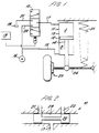
- FIG. 1 there can be seen a vehicle suspension device according to the prior art.
- the vehicle suspension device comprises valve means 10 and an actuator 11.
- the actuator 11 comprises a piston 12 which acts within a cylinder 13.
- the piston 12 divides the cylinder 13 into two chambers A and B.
- the piston 12 is connected via an arm 14 to a suspension linkage 24 which is in turn connected to a wheel and hub assembly 25 of the vehicle.
- the bottom chamber B of the actuator 11 is permanently connected via a line 15 to a source of pressurised fluid 16.
- the top chamber A of the actuator 11 is connected by line 17 to the valve means 10.
- the valve means 10 is controlled by an electrical control signal generated by a processor 18.
- the valve means 10 can connect the chamber A to either the source of pressurised fluid 16 or to an exhaust for pressurised fluid 19.
- the valve means 10 meters the flow of hydraulic fluid into and out of the chamber A to control motion of the piston 12 within the cylinder 13.
- valve means 10 A typical configuration of the valve means 10 can be seen in Figure 2.
- the valve means 10 comprises a spool member 20 which can be controlled to move in an axial direction within a surrounding housing.
- the spool valve is shown in its centered position in which the chamber A is neither connected to the exhaust for pressurised fluid 19 nor to the source of pressurised fluid 16.
- Displacement of the member 20 to the left as shown in the figure allows fluid to flow from the passage 17 to a "return" passage 21 which is connected to the exhaust for pressurised fluid 19.
- Motion of the member 20 to the right of its position shown in Figure 2 connects the chamber 17 to the source of pressurised fluid 16 via a "source" line 22.
- the spool valve 10 controls the amount of fluid flowing into the chamber A by varying the restriction on fluid passing from the source line 22 via an annular cavity 23 defined in the member 20 to the line 17.
- the spool valve 10 similarly controls the flow of fluid out of the chamber A by restricting the flow of fluid from the line 19 via the annular cavity 23 out into the return line 21.
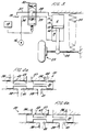
- the first embodiment of the vehicle suspension device according to the invention can be seen in Figure 3.
- the embodiment comprises the same actuator 11 as shown in the prior art system of Figure 1 and like components shall be referenced accordingly.
- the actuator 11 comprises a piston 12 acting within a cylinder 13.
- the piston 12 is again connected via a rod 14 extending out of the cylinder 13 to a suspension arm 24. Movement of the piston 12 within the cylinder 13 causes associated motion of the suspension linkage 24 and an associated assembly 25.
- the first embodiment according to the present invention differs from the prior art vehicle suspension device in incorporating a different valve means 30.
- valve means 30 The spool arrangement for the valve means 30 can be seen in Figures 4a and 4b in two different positions.
- the valve means 30 is controlled by electrical control signals generated by processing means 18.
- the valve means 30 controls the flow of fluid to and from the chambers A and B by motion of a spool member 31 within the valve housing.
- the spool member 31 moves in response to the electrical control signals received from the processing means 18.
- the valve means 30 has two operating conditions. In the first operating condition, shown in Fig 4a, the chamber B is connected by lines 39 and 36 and the annular cavity 41 to the source 16, whilst the fluid flowing into and out of chamber A is metered by the valve means.
- the valve means meters the flow of fluid into and out of chamber A by controlling the flow of fluid from passage 36 and to passage 37 via the annular cavity 40 in the spool member 31.
- the spool valve meters the flow by controlling the position of the two edges 42 and 43. By controlling the flow of fluid, the valve means controls movement of the piston 12.
- the chamber A In the second operating condition the chamber A is connected to the source for pressurised fluid whilst the flow of fluid out of the chamber B is metered, which corresponds to the spool valve position shown in Figure 4b.
- the maximum upward force on the piston is the same as in the embodiment of the prior art and occurs when the pressure in chamber B is system pressure Ps and the chamber A is connected to the exhaust for pressurised fluid in chamber A, the pressure therein therefore being zero.
- the maximum downward force on the piston 12 that can be achieved by the embodiment of the invention as shown in Figure 3 is twice the value of the maximum achievable downward force of the embodiment shown in Figure 1 for the same system pressure Ps.
- the maximum downward force upon the piston 12 is achieved when the system pressure of Ps is prevalent in chamber A and chamber B is connected to the exhaust for pressurised fluid 19, therefore the pressure of the fluid in chamber B is zero.
- we shall take the surface area of the piston surface acting in chamber B to be A1 and the surface area of the surface of the piston acting in chamber A to be twice that area, that is to say 2A1. Therefore the maximum downward force is Ps x 2A1 - zero x A1 +2PsA1 .
- the spool valve of the invention controls the velocity of motion of the piston 12 in both operating conditions shown in Figures 4a, 4b described before.
- the bottom chamber B is connected to the source of pressurised fluid and the pressure of the fluid within chamber B is Ps.
- the flow of fluid into and out of chamber A is metered by the valve which controls the velocity of the piston by controlling the flow of fluid.
- chamber B is kept at full system pressure by the valve means and the pressure of the fluid in chamber A is selected to be system pressure or zero by positioning the spool valve to either meter supply to the chamber A from supply or to meter fluid expelled from chamber A to exhaust.
- the valve means 30 controls the movement of the piston 12 by controlling the magnitude of the flow of fluid either from the inlet 36 or to the outlet 37 via the annular aperture 40 using the two spool member edges 42 and 43.
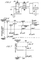
- the valve means in the first operating condition can achieve the "authority" shown graphically in Figure 6 as case 5 when operating at a system pressure of 50% Ps.
- the valve means in the second condition connects the chamber A to system pressure and connects the chamber B to the exhaust for pressurised fluid and meters the flow of fluid out of chamber B to control piston velocity.
- Chamber A is always connected to the source 16 in the second operating condition and the spool member 31 is controlled to vary the magnitude of the flow of fluid from chamber B to the exhaust 17, thereby controlling piston movement.
- the spool member controls the velocity of piston 12 by limiting the fluid flowing through the annular cavity 41 to the outlet 37 by controlling the edge 44 of the spool member 41.
- the valve means can cause the actuator to operate with the authority shown as case 6 in Figure 6.
- the downward maximum force achievable is PsA1. Therefore when the actuator is operated using the valve with a system pressure of 50% Ps, the actuator can still achieve a maximum downward force of PsA1, equivalent to the maximum downward force achievable using the actuator of Figure 1 with a system pressure of 100% Ps.
- a spring 35 acting in parallel with the actuator 11 takes the full static weight of the automobile at the mid-range of the "authority" of the actuator, so that the actuator is always attempting to extend the spring or contract the spring when moving the wheel/hub assembly.
- the static weight of the vehicle is the weight of the vehicle that acts on the actuator and spring when the sprung mass of the vehicle is stationary.
- the actuator 11 of Figure 3 again acts in parallel with the spring 35 to support the vehicle body.
- the problem of the difference in magnitudes between the maximum upward force and the maximum downward force that can be applied to the piston of the actuator controlled by valve means 30 can be overcome by allowing the actuator to support a portion of the static weight of the vehicle such that the authority of the system matches the required authority window.
- downward force is applied on the piston to support some of the static weight of the vehicle, and the spring 35 supports less than the total static weight of the vehicle.
- This shift can be seen as cases 9 and 10 in Figure 7. Whereas no force is applied across the piston of the prior art when the vehicle is stationery, in the preferred embodiment of the present invention a force is applied to support a portion of the vehicle weight which we shall call W 1 .
- Case 9 represents the authority of the actuator 11 with the valve means 30 in the first operating condition and with the actuator 11 supporting some of the static weight of the vehicle.
- Case 10 represents the authority of the actuator 11 with valve means 30 in the second operating condition and with the actuator 11 supporting some of the same weight of the vehicle.
- the maximum authority required is achieved with a system pressure that is 66% of the system pressure required by the prior art system to achieve the same maximum authority.
- a second embodiment of the present invention can be seen in Figure 5.
- the embodiment shown in Figure 5 operates in essentially the same manner as the embodiment shown in Figure 3.
- the system uses two valves, a spool valve 50 and a switching valve 51.
- the switching valve 51 is a simple valve which has two positions. In the first position the valve 51 connects the chamber B to the source of system pressure 16 whilst connecting the chamber A to the spool valve 50.
- the spool valve 50 then meters the flow of fluid into and out of the chamber A, selectively connecting the chamber A to either the source of pressurised fluid to the exhaust for pressurised fluid.
- the actuator of the present invention provides an improvement over the previous unequal area actuator as shown in Figure 1, since the system can operate with a full operating window of authority at two-thirds of the system pressure required by the previous actuator to operate with the same operating window.
- the invention also provides an improvement over those systems of the prior art which use valves adapted to connect one chamber of an actuator to either a source of pressurised fluid when the other is connected to an exhaust and vice versa.
- the present system uses a valve which connects one side of the actuator fully to a source of pressurised fluid and selectively connects the other side to either a source of pressurised fluid or exhaust meters the flow into or out of only one of the chambers. A simplified valve arrangement is therefore accomplished.
- the system described above provides an actuator which can operate with a system pressure of two-thirds of the system pressure that will be required by the "unequal area" actuators of the prior art.
- the saving in system pressure is advantageous since less power is required to operate the system and therefore the efficiency of the engine power of the car is less impaired.
- the decrease in system pressure lessens the problems of keeping the system fluid tight and results in reduced leakage out of the pressurised system.
Abstract
Claims (9)
- Dispositif de suspension de véhicule comprenant :
un actionneur (11) ayant un piston (12) contenu dans un cylindre (13), lequel piston (12) divise le cylindre (13) en au moins deux chambres (A, B), une première surface du piston (12) travaillant dans une première chambre (B) du cylindre ayant une aire plus petite qu'une seconde surface du piston (12) travaillant dans une seconde chambre (A),
une source de fluide pressurisé (16),
une évacuation de fluide pressurisé (19), et
un moyen de soupape (30 ; 50 ; 51) dans lequel
le moyen de soupape (30) a un premier état de fonctionnement dans lequel le moyen de soupape (30 ; 50 ; 51) a deux modes de fonctionnement, un premier mode de fonctionnement dans lequel le moyen de soupape (30, 50, 51) relie les deux première et seconde chambres (A,B) à la source de fluide pressurisé (16) et un second mode dans lequel le moyen de soupape (30; 50 ; 51) relie la première chambre (B) à la source de fluide pressurisé et relie la seconde chambre (A) à l'évacuation de fluide pressurisé (19), le moyen de soupape dans le premier état de fonctionnement mesurant le débit de fluide dans ou en sortie soit de la première soit de la seconde des chambres (A,B) pour commander le mouvement du piston,
caractérisé en ce que le moyen de soupape a un second état de fonctionnement dans lequel le moyen de soupape (30 ; 50 ; 51) relie la seconde chambre (A) à la source de fluide pressurisé (16) et relie la première chambre (B) à l'évacuation de fluide pressurisé (19), le moyen de soupape (30 ; 50 ; 51) mesurant le débit de fluide en sortie de la première chambre (B) pour commander le mouvement du piston. - Dispositif de suspension de véhicule selon la revendication 1, caractérisé en ce que l'actionneur (11) fonctionne en parallèle avec un moyen élastique (35) pour supporter le poids du véhicule.
- Dispositif de suspension de véhicule selon la revendication 2, caractérisé en ce qu'une partie du poids statique du véhicule est supportée par l'actionneur (11), le dispositif de suspension de véhicule appliquant vers le bas une force sur le piston (12) lorsque le véhicule est immobile pour supporter une partie du poids statique.
- Dispositif de suspension de véhicule selon l'une quelconque des revendications précédentes caractérisé en ce que le moyen de soupape comprend une soupape à quatre portes (30) qui relie sélectivement l'une des chambres (A, B) à la source de fluide pressurisé (16), tout en mesurant le débit en sortie de l'autre chambre (A, B) vers l'évacuation de fluide pressurisé (19).
- Dispositif de suspension de véhicule selon l'une quelconque des revendications précédentes caractérisé en ce que le moyen de soupape comprend une soupape à quatre portes (30), qui relie sélectivement l'une des chambres (A, B) à la source de fluide pressurisé (16), tout en mesurant le débit dans l'autre chambre (A, B) en provenance de la source de fluide pressurisé (16).
- Dispositif de suspension de véhicule selon l'une quelconque des revendications 1, 2 ou 3 caractérisé en ce que le moyen de soupape comprend deux soupapes, une soupape de commutation à quatre portes (51) ayant seulement deux positions de fonctionnement et une soupape à tiroir à trois portes (50), caractérisé en ce que la soupape à quatre portes (51) relie sélectivement l'une des chambres (A, B) à la source de fluide pressurisé (16) tout en reliant l'autre chambre (A, B) à la soupape à tiroir à trois portes (50) et la soupape à tiroir à trois portes (50) peut mesurer le débit de fluide dans cette dernière chambre en provenance de la source de fluide pressurisé (16) et peut mesurer le débit de fluide en sortie de cette dernière chambre vers l'évacuation de fluide pressurisé (19).
- Dispositif de suspension de véhicule selon l'une quelconque des revendications précédentes caractérisé en ce qu'une tige (14) fixée à la première surface du piston (12) s'étend longitudinalement dans la première chambre (B) et à travers une ouverture ménagée dans une paroi de celle-ci pour relier le piston (12) à un montage roue-moyeu (24, 25), formant ainsi l'aire réduite de la première surface du piston (12) en comparaison avec la seconde surface de ce dernier.
- Dispositif de suspension de véhicule selon l'une quelconque des revendications précédentes comprenant un microprocesseur (18) pour générer des signaux pour commander le moyen de soupape (30 ; 50 ; 51).
- Système de suspension active pour un véhicule comprenant des dispositifs de suspension de véhicule selon l'une quelconque des revendications précédentes.
Applications Claiming Priority (3)
| Application Number | Priority Date | Filing Date | Title |
|---|---|---|---|
| GB919102059A GB9102059D0 (en) | 1991-01-31 | 1991-01-31 | A vehicle suspension device |
| GB9102059 | 1991-01-31 | ||
| PCT/GB1992/000183 WO1992013731A1 (fr) | 1991-01-31 | 1992-01-31 | Systeme de suspension de vehicule |
Publications (2)
| Publication Number | Publication Date |
|---|---|
| EP0569429A1 EP0569429A1 (fr) | 1993-11-18 |
| EP0569429B1 true EP0569429B1 (fr) | 1996-08-21 |
Family
ID=10689282
Family Applications (1)
| Application Number | Title | Priority Date | Filing Date |
|---|---|---|---|
| EP92903707A Expired - Lifetime EP0569429B1 (fr) | 1991-01-31 | 1992-01-31 | Systeme de suspension de vehicule |
Country Status (6)
| Country | Link |
|---|---|
| EP (1) | EP0569429B1 (fr) |
| JP (1) | JPH06504745A (fr) |
| DE (1) | DE69212989T2 (fr) |
| ES (1) | ES2094343T3 (fr) |
| GB (1) | GB9102059D0 (fr) |
| WO (1) | WO1992013731A1 (fr) |
Cited By (1)
| Publication number | Priority date | Publication date | Assignee | Title |
|---|---|---|---|---|
| WO2010149149A2 (fr) | 2009-06-24 | 2010-12-29 | German Gresser | Système d'amortissement produisant du courant pour véhicules hybrides et électriques |
Families Citing this family (5)
| Publication number | Priority date | Publication date | Assignee | Title |
|---|---|---|---|---|
| GB9302152D0 (en) * | 1993-02-04 | 1993-03-24 | Lotus Car | Vehicle suspension device |
| US5682980A (en) * | 1996-02-06 | 1997-11-04 | Monroe Auto Equipment Company | Active suspension system |
| GB9902182D0 (en) * | 1999-02-02 | 1999-03-24 | Prodrive Holdings Ltd | Vehicle suspension system |
| DE102004039973B4 (de) * | 2003-08-25 | 2017-02-02 | Iav Gmbh Ingenieurgesellschaft Auto Und Verkehr | Aktive Fahrwerkaufhängung für Fahrzeuge |
| IT202000015142A1 (it) * | 2020-06-24 | 2021-12-24 | Way Assauto S R L | Sospensione attiva per veicolo |
Family Cites Families (9)
| Publication number | Priority date | Publication date | Assignee | Title |
|---|---|---|---|---|
| US2802674A (en) * | 1955-11-16 | 1957-08-13 | Gen Motors Corp | Roll control system for a motor vehicle |
| US3191954A (en) * | 1963-09-30 | 1965-06-29 | Drott Mfg Corp | Leveling and suspension system for wheeled vehicle |
| GB1456873A (en) * | 1973-06-30 | 1976-12-01 | Nissan Motor | Vehicle having a fluid operated vehicle body level control system |
| US4090723A (en) * | 1977-01-24 | 1978-05-23 | Caterpillar Tractor Co. | Tandem roadwheel leveling system for construction vehicles |
| US4706989A (en) * | 1985-06-12 | 1987-11-17 | Nissan Motor Co., Ltd. | Rear independent suspension for automotive vehicle |
| DE3616541A1 (de) * | 1986-05-16 | 1987-11-19 | Kuebler Allan J | Antineigungseinrichtung fuer fahrzeuge |
| CA1299207C (fr) * | 1987-01-08 | 1992-04-21 | Charles B. Steger | Actionneur hydraulique double action pour suspension active |
| DE3742883A1 (de) * | 1987-12-17 | 1989-07-06 | Rexroth Mannesmann Gmbh | Ventilanordnung fuer einen daempfungszylinder zur schwingungsdaempfung von radfahrzeugen |
| EP0424784A3 (en) * | 1989-10-26 | 1991-08-07 | Volkswagen Aktiengesellschaft | Hydraulic positioning equipment producing a positioning force which is controllable with regards to its direction and magnitude |
-
1991
- 1991-01-31 GB GB919102059A patent/GB9102059D0/en active Pending
-
1992
- 1992-01-31 ES ES92903707T patent/ES2094343T3/es not_active Expired - Lifetime
- 1992-01-31 EP EP92903707A patent/EP0569429B1/fr not_active Expired - Lifetime
- 1992-01-31 DE DE69212989T patent/DE69212989T2/de not_active Expired - Fee Related
- 1992-01-31 JP JP4503291A patent/JPH06504745A/ja active Pending
- 1992-01-31 WO PCT/GB1992/000183 patent/WO1992013731A1/fr active IP Right Grant
Cited By (2)
| Publication number | Priority date | Publication date | Assignee | Title |
|---|---|---|---|---|
| WO2010149149A2 (fr) | 2009-06-24 | 2010-12-29 | German Gresser | Système d'amortissement produisant du courant pour véhicules hybrides et électriques |
| DE102009060999A1 (de) | 2009-06-24 | 2011-01-05 | German Gresser | Energieoptimiertes Elektrofahrzeug mit autarker Stromversorgung und Verfahren zur Stromerzeugung, bevorzugt aus kinetischer und Gravitationsenergie |
Also Published As
| Publication number | Publication date |
|---|---|
| GB9102059D0 (en) | 1991-03-13 |
| DE69212989D1 (de) | 1996-09-26 |
| ES2094343T3 (es) | 1997-01-16 |
| WO1992013731A1 (fr) | 1992-08-20 |
| EP0569429A1 (fr) | 1993-11-18 |
| JPH06504745A (ja) | 1994-06-02 |
| DE69212989T2 (de) | 1997-03-13 |
Similar Documents
| Publication | Publication Date | Title |
|---|---|---|
| US4456434A (en) | Power transmission | |
| US5348338A (en) | Active vehicle suspension system | |
| EP0249227B2 (fr) | Système de suspension de véhicule à contrÔle actif comportant des systèmes hydrauliques indépendants ayant des caractéristiques d'amortissement différentes pour améliorer les charactéristiques de réponse dans le contrÔle actif de la suspension | |
| EP0569429B1 (fr) | Systeme de suspension de vehicule | |
| EP0427865A4 (en) | Hydraulic driving device of construction equipment | |
| US5678846A (en) | Vehicle suspension device | |
| JP2000130494A (ja) | 変化させられ得る減衰力を有する振動ダンパ | |
| EP0828946B1 (fr) | Bloc de commande hydraulique | |
| US5110152A (en) | Active suspension system | |
| US5273297A (en) | Leveling system for vehicles | |
| JP2534255B2 (ja) | 車両用油圧供給装置 | |
| US5090726A (en) | Suspension control system | |
| KR970700288A (ko) | 작동시스템 | |
| JP2506331B2 (ja) | 能動制御型サスペンシヨン装置 | |
| JPH0788134B2 (ja) | 能動型サスペンシヨン装置 | |
| JPH09328007A (ja) | 車高調整装置 | |
| JP3535951B2 (ja) | 油圧ショベルの油圧駆動装置 | |
| KR20000048508A (ko) | 미끄럼방지 제어장치를 구비한 자동차용 유압 제동 시스템 | |
| EP0426725B1 (fr) | Amortisseur | |
| GB2222445A (en) | Suspension control device | |
| JPH07103360A (ja) | 流量制御弁 | |
| JPH0638723Y2 (ja) | 流体圧式サスペンションの流体回路装置 | |
| JPH078247Y2 (ja) | 車高調整装置 | |
| JPH0517202U (ja) | 油圧駆動装置 | |
| JPH03235753A (ja) | 液圧制御装置 |
Legal Events
| Date | Code | Title | Description |
|---|---|---|---|
| PUAI | Public reference made under article 153(3) epc to a published international application that has entered the european phase |
Free format text: ORIGINAL CODE: 0009012 |
|
| 17P | Request for examination filed |
Effective date: 19930813 |
|
| AK | Designated contracting states |
Kind code of ref document: A1 Designated state(s): BE DE ES FR GB IT SE |
|
| 17Q | First examination report despatched |
Effective date: 19941122 |
|
| GRAH | Despatch of communication of intention to grant a patent |
Free format text: ORIGINAL CODE: EPIDOS IGRA |
|
| GRAH | Despatch of communication of intention to grant a patent |
Free format text: ORIGINAL CODE: EPIDOS IGRA |
|
| GRAA | (expected) grant |
Free format text: ORIGINAL CODE: 0009210 |
|
| AK | Designated contracting states |
Kind code of ref document: B1 Designated state(s): BE DE ES FR GB IT SE |
|
| REF | Corresponds to: |
Ref document number: 69212989 Country of ref document: DE Date of ref document: 19960926 |
|
| ET | Fr: translation filed | ||
| ITF | It: translation for a ep patent filed |
Owner name: STUDIO TORTA SOCIETA' SEMPLICE |
|
| REG | Reference to a national code |
Ref country code: ES Ref legal event code: FG2A Ref document number: 2094343 Country of ref document: ES Kind code of ref document: T3 |
|
| PGFP | Annual fee paid to national office [announced via postgrant information from national office to epo] |
Ref country code: SE Payment date: 19970117 Year of fee payment: 6 |
|
| PGFP | Annual fee paid to national office [announced via postgrant information from national office to epo] |
Ref country code: GB Payment date: 19970124 Year of fee payment: 6 |
|
| PGFP | Annual fee paid to national office [announced via postgrant information from national office to epo] |
Ref country code: FR Payment date: 19970128 Year of fee payment: 6 |
|
| PGFP | Annual fee paid to national office [announced via postgrant information from national office to epo] |
Ref country code: ES Payment date: 19970131 Year of fee payment: 6 |
|
| PGFP | Annual fee paid to national office [announced via postgrant information from national office to epo] |
Ref country code: BE Payment date: 19970203 Year of fee payment: 6 |
|
| PGFP | Annual fee paid to national office [announced via postgrant information from national office to epo] |
Ref country code: DE Payment date: 19970318 Year of fee payment: 6 |
|
| PLBE | No opposition filed within time limit |
Free format text: ORIGINAL CODE: 0009261 |
|
| STAA | Information on the status of an ep patent application or granted ep patent |
Free format text: STATUS: NO OPPOSITION FILED WITHIN TIME LIMIT |
|
| 26N | No opposition filed | ||
| PG25 | Lapsed in a contracting state [announced via postgrant information from national office to epo] |
Ref country code: GB Free format text: LAPSE BECAUSE OF NON-PAYMENT OF DUE FEES Effective date: 19980131 Ref country code: FR Free format text: THE PATENT HAS BEEN ANNULLED BY A DECISION OF A NATIONAL AUTHORITY Effective date: 19980131 Ref country code: BE Free format text: LAPSE BECAUSE OF NON-PAYMENT OF DUE FEES Effective date: 19980131 |
|
| PG25 | Lapsed in a contracting state [announced via postgrant information from national office to epo] |
Ref country code: SE Free format text: LAPSE BECAUSE OF NON-PAYMENT OF DUE FEES Effective date: 19980201 |
|
| PG25 | Lapsed in a contracting state [announced via postgrant information from national office to epo] |
Ref country code: ES Free format text: LAPSE BECAUSE OF EXPIRATION OF PROTECTION Effective date: 19980202 |
|
| BERE | Be: lapsed |
Owner name: TRW INC. Effective date: 19980131 Owner name: LOTUS CARS LTD Effective date: 19980131 |
|
| GBPC | Gb: european patent ceased through non-payment of renewal fee |
Effective date: 19980131 |
|
| PG25 | Lapsed in a contracting state [announced via postgrant information from national office to epo] |
Ref country code: DE Free format text: LAPSE BECAUSE OF NON-PAYMENT OF DUE FEES Effective date: 19981001 |
|
| REG | Reference to a national code |
Ref country code: FR Ref legal event code: ST |
|
| EUG | Se: european patent has lapsed |
Ref document number: 92903707.5 |
|
| REG | Reference to a national code |
Ref country code: ES Ref legal event code: FD2A Effective date: 20000601 |
|
| PG25 | Lapsed in a contracting state [announced via postgrant information from national office to epo] |
Ref country code: IT Free format text: LAPSE BECAUSE OF NON-PAYMENT OF DUE FEES;WARNING: LAPSES OF ITALIAN PATENTS WITH EFFECTIVE DATE BEFORE 2007 MAY HAVE OCCURRED AT ANY TIME BEFORE 2007. THE CORRECT EFFECTIVE DATE MAY BE DIFFERENT FROM THE ONE RECORDED. Effective date: 20050131 |