EP0568512A1 - Plaquette de coupe pour outil de tournage et de rainurage - Google Patents
Plaquette de coupe pour outil de tournage et de rainurage Download PDFInfo
- Publication number
- EP0568512A1 EP0568512A1 EP93850085A EP93850085A EP0568512A1 EP 0568512 A1 EP0568512 A1 EP 0568512A1 EP 93850085 A EP93850085 A EP 93850085A EP 93850085 A EP93850085 A EP 93850085A EP 0568512 A1 EP0568512 A1 EP 0568512A1
- Authority
- EP
- European Patent Office
- Prior art keywords
- insert
- recesses
- insert according
- ridge portions
- recess
- Prior art date
- Legal status (The legal status is an assumption and is not a legal conclusion. Google has not performed a legal analysis and makes no representation as to the accuracy of the status listed.)
- Granted
Links
- 238000005520 cutting process Methods 0.000 title claims abstract description 24
- 230000007935 neutral effect Effects 0.000 claims description 5
- 239000002184 metal Substances 0.000 claims description 3
- 230000001154 acute effect Effects 0.000 description 3
- 238000004519 manufacturing process Methods 0.000 description 2
- 238000010276 construction Methods 0.000 description 1
- 230000003247 decreasing effect Effects 0.000 description 1
- 230000002349 favourable effect Effects 0.000 description 1
- 230000020169 heat generation Effects 0.000 description 1
- 238000007493 shaping process Methods 0.000 description 1
- 230000007704 transition Effects 0.000 description 1
Images


Classifications
-
- B—PERFORMING OPERATIONS; TRANSPORTING
- B23—MACHINE TOOLS; METAL-WORKING NOT OTHERWISE PROVIDED FOR
- B23B—TURNING; BORING
- B23B27/00—Tools for turning or boring machines; Tools of a similar kind in general; Accessories therefor
- B23B27/04—Cutting-off tools
- B23B27/045—Cutting-off tools with chip-breaking arrangements
-
- B—PERFORMING OPERATIONS; TRANSPORTING
- B23—MACHINE TOOLS; METAL-WORKING NOT OTHERWISE PROVIDED FOR
- B23B—TURNING; BORING
- B23B27/00—Tools for turning or boring machines; Tools of a similar kind in general; Accessories therefor
- B23B27/22—Cutting tools with chip-breaking equipment
-
- B—PERFORMING OPERATIONS; TRANSPORTING
- B23—MACHINE TOOLS; METAL-WORKING NOT OTHERWISE PROVIDED FOR
- B23B—TURNING; BORING
- B23B2205/00—Fixation of cutting inserts in holders
- B23B2205/02—Fixation using an elastically deformable clamping member
-
- B—PERFORMING OPERATIONS; TRANSPORTING
- B23—MACHINE TOOLS; METAL-WORKING NOT OTHERWISE PROVIDED FOR
- B23B—TURNING; BORING
- B23B2210/00—Details of turning tools
-
- B—PERFORMING OPERATIONS; TRANSPORTING
- B23—MACHINE TOOLS; METAL-WORKING NOT OTHERWISE PROVIDED FOR
- B23B—TURNING; BORING
- B23B2260/00—Details of constructional elements
- B23B2260/124—Screws
-
- B—PERFORMING OPERATIONS; TRANSPORTING
- B23—MACHINE TOOLS; METAL-WORKING NOT OTHERWISE PROVIDED FOR
- B23B—TURNING; BORING
- B23B27/00—Tools for turning or boring machines; Tools of a similar kind in general; Accessories therefor
- B23B27/02—Cutting tools with straight main part and cutting edge at an angle
-
- Y—GENERAL TAGGING OF NEW TECHNOLOGICAL DEVELOPMENTS; GENERAL TAGGING OF CROSS-SECTIONAL TECHNOLOGIES SPANNING OVER SEVERAL SECTIONS OF THE IPC; TECHNICAL SUBJECTS COVERED BY FORMER USPC CROSS-REFERENCE ART COLLECTIONS [XRACs] AND DIGESTS
- Y10—TECHNICAL SUBJECTS COVERED BY FORMER USPC
- Y10T—TECHNICAL SUBJECTS COVERED BY FORMER US CLASSIFICATION
- Y10T407/00—Cutters, for shaping
- Y10T407/24—Cutters, for shaping with chip breaker, guide or deflector
- Y10T407/245—Cutters, for shaping with chip breaker, guide or deflector comprising concave surface in cutting face of tool
-
- Y—GENERAL TAGGING OF NEW TECHNOLOGICAL DEVELOPMENTS; GENERAL TAGGING OF CROSS-SECTIONAL TECHNOLOGIES SPANNING OVER SEVERAL SECTIONS OF THE IPC; TECHNICAL SUBJECTS COVERED BY FORMER USPC CROSS-REFERENCE ART COLLECTIONS [XRACs] AND DIGESTS
- Y10—TECHNICAL SUBJECTS COVERED BY FORMER USPC
- Y10T—TECHNICAL SUBJECTS COVERED BY FORMER US CLASSIFICATION
- Y10T407/00—Cutters, for shaping
- Y10T407/25—Cutters, for shaping including cut off tool
Definitions
- the present invention relates to a cutting insert for turning and grooving tools, primarily for grooving operations in metall workpieces, that could also be useful for cutting off rods, tubes or other rotationally symmetrical details.
- Such cutting insert is provided with a cutting edge formed by the transition between the top surface or rake surface of the insert and its forward clearance face.
- the dimpled chipbreaker and the confining walls thereof are designed so as to form the chip narrower than the groove such that more, efficiently manageable safe chips can be obtained. Chip disposal should become safer and more efficient and less costly. With such inserts it shall become possible to generate a finished groove in one pass in the workpiece such as a crankshaft.
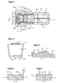
- the insert is in the shape of a polygonal body of generally Parallepipedic shape. It comprises two mainly Plane-parallel side surfaces 11, 12, opposed top and bottom surfaces 14 and 13 respectively, two end surfaces 15, 16, and a shoulder 17.
- the front portion of the insert is provided with a main cutting edge 18 and a chip forming device 19.
- the insert is intended to be secured to a holder body provided with an integral clamping arm.
- the top surface 14 is broken at the vicinity of the shoulder 17 so that surface portion 14a forms an acute angle with the remainder of said surface 14.
- the insert 10 is intended to be removably held in a holder, which comprises a holder body 20 having an integral clamping arm 21 in the front portion 22 of said holder body 20 and an insert receiving recess 23 in which the insert is to be located.
- the recess 23 communicates at an inner end thereof with an elongated slit 24 which terminates into a circular recess 25.
- a clamping screw 26 extends into the holder through the clamping arm 21 and through the slit 24. When the screw 26 is threaded into the holder the clamping arm 21 flexes downwardly about said recess 23 and causes the clamping arm 21 into firm clamping abutment with the upper top surface of the insert. More specifically, the nose portion of the clamping arm 21 is somewhat inclined downwardly so that it matches the inclination of upper surface portion 14a of the insert 10.
- Bottom surface 13 is intended to be a first support surface for the insert against the holder body which shall be parallel with a neutral plane P defined by the axial feed direction of the machine. More specifically bottom surfaces includes two distantly provided flat surface portions 13a and 13d, and two inclined surfaces 13b and 13c therebetween, whereby said inclined surfaces 13b, 13c provide a V-shaped recess.
- the surfaces 13b and 13c are intended to be in abutment with correspondingly inclined surfaces in the insert site of the holder as shown in Fig 6 and 7. As appears therefrom the surfaces 13a and 13d are not to be active support surfaces.
- the top surface 14 constitutes a second support surface for the insert against the holder body. The top surface 14 is oriented parallel with the bottom surface 13.
- the cutting edge 18 is straight and is formed along the intersection line of clearance face 16 and a primary land 27.
- the land 27 is bordered radially inwardly by an array of spaced recesses or grooves 28 extending on the rake face of the insert starting from the primary land 27.
- the width of the land 27 is varying along the edge 18 in such a way that the width is smaller at those portions located next to the front end portions of each recess 28 whereas the width is larger at the inclined rake surface portions 29 located therebetween.
- the maximum width of each recess 28 is preferably larger than the distance between the depressions.
- Each recess has a depth initially increasing in a direction away from said primary land and thereafter decreasing in said direction.
- oval-shaped recesses 28 having a longitudinal extension, perpendicularly from the cutting edge 18, that is several times larger than the width of said recess 28. Additionally there is, on each side of said central group of oval-shaped recesses 28 a recess 30 having a larger width and shorter length than each of said central recesses 28.
- a recess 31 which curves inwardly and downwardly from the land surface 27 and then curves upwardly to form a rear wall or chip deflector surface 32.
- the chip deflector surface 32 terminates in a plateau 33 located approximately at the same level as the neutral plane P.
- the chipforming device 19 additionally includes a pair of ridges 34, each of which extends from the outer periphery of the recess 30. More specifically, the front ridge portion 34a and 34b are so formed that they converge rearwardly, and they extend rearwardly to the point where they meet with rear ridge portions 35a and 35b which are mutually parallel and extending essentially perpendicularly from the cutting edge 18. Furthermore, the said front ridge portions 34a and 34b are formed with a top surface that is raised rearwardly until the portion where said front ridge 34a, 34b intersect with said rear straight ridge 35a, 35b at which intersection the top surface of said rear ridge has a level that remains constant furtheron rearwardly. This level of the upper surface of said rear ridges is located somewhat above plane P.
- the ridges as aforesaid it is ensured that the chip remains in contact with said forward ridge portions 34a, 34b and the central portion of the chip is urged deeper into the recess 31 which means that the total width of the chip is made narrower and becomes more easily manageable so that no harm is made from the chip on to the side walls of the groove which is to be formed by said insert during cutting in a metal workpiece.
- the forward end of the insert 10 additionally is provided with side cutting edges 36a and 36b, which merge rearwardly to an intermediate position along the insert, whilst intersecting with the land surface 27 which extends along both the main cutting edge 18 and along said side cutting edges 36a, 36b.
- the clearance faces of said side cutting edges 36a, 36b are designated 11a and 11b whereby each said clearance face 11a, 11b intersect with the land 27 at an acute angle ⁇ .
- the chip forming device By virtue of the particular construction of the chip forming device as aforesaid it will be possible to obtain desirable clock-shaped chips 37 such as shown in Fig 8, obtained at a feed rate of 0,30 mm/revolution. If no proper chip deflection device is provided into the upper rake surface of the insert chips obtained would otherwise be difficult to manage. Also at moderate feed rates the chip forming device of this invention effectively contributes to the control and removal of such chips. When large feeds are used the chip will be pressed against the rear wall 32 of recess 31 which forces the chip to be bent in a favourable manner.
- the embodiment described above also results in a certain reduction of the cutting forces because these grooves mean reduced contact area and increased positive rake angle. Due to the fact that a reduced contact area is obtained a relatively low heat generation is obtained.
Landscapes
- Engineering & Computer Science (AREA)
- Mechanical Engineering (AREA)
- Cutting Tools, Boring Holders, And Turrets (AREA)
- Milling Processes (AREA)
- Finish Polishing, Edge Sharpening, And Grinding By Specific Grinding Devices (AREA)
- Threshing Machine Elements (AREA)
Applications Claiming Priority (2)
| Application Number | Priority Date | Filing Date | Title |
|---|---|---|---|
| SE9201364 | 1992-04-30 | ||
| SE9201364A SE508121C2 (sv) | 1992-04-30 | 1992-04-30 | Skär för svarvnings- och spårstickningsverktyg |
Publications (2)
| Publication Number | Publication Date |
|---|---|
| EP0568512A1 true EP0568512A1 (fr) | 1993-11-03 |
| EP0568512B1 EP0568512B1 (fr) | 1996-06-26 |
Family
ID=20386108
Family Applications (1)
| Application Number | Title | Priority Date | Filing Date |
|---|---|---|---|
| EP93850085A Expired - Lifetime EP0568512B1 (fr) | 1992-04-30 | 1993-04-16 | Plaquette de coupe pour outil de tournage et de rainurage |
Country Status (8)
| Country | Link |
|---|---|
| US (1) | US5375948A (fr) |
| EP (1) | EP0568512B1 (fr) |
| JP (1) | JP2744574B2 (fr) |
| KR (1) | KR960011076B1 (fr) |
| AT (1) | ATE139718T1 (fr) |
| DE (1) | DE69303325T2 (fr) |
| ES (1) | ES2089779T3 (fr) |
| SE (1) | SE508121C2 (fr) |
Cited By (13)
| Publication number | Priority date | Publication date | Assignee | Title |
|---|---|---|---|---|
| DE4402759A1 (de) * | 1994-01-31 | 1995-08-03 | Widia Heinlein Gmbh | Schneideinsatz |
| WO1995025611A1 (fr) * | 1994-03-18 | 1995-09-28 | Sandvik Ab | Element diamante incluant un dispositif d'enlevement de copeaux |
| DE19523127A1 (de) * | 1994-07-05 | 1996-01-11 | Valenite Inc | Schneideneinsatz |
| DE19523129A1 (de) * | 1994-07-05 | 1996-01-25 | Valenite Inc | Schneideinsatz |
| DE4433389A1 (de) * | 1994-09-12 | 1996-03-14 | Widia Gmbh | Stecheinsatz zur spanabhebenden Bearbeitung von Werkstücken |
| WO1996008330A1 (fr) * | 1994-09-12 | 1996-03-21 | Widia Gmbh | Plaquette pour usinage de pieces par enlevement de copeaux |
| WO1997004907A1 (fr) * | 1995-07-28 | 1997-02-13 | Widia Gmbh | Plaquette d'outil a saigner |
| EP0775544A1 (fr) * | 1995-11-23 | 1997-05-28 | Sandvik Aktiebolag | Plaquette de coupe pour le rainurage et pour l'élargissement des rainures |
| DE10006303A1 (de) * | 2000-02-12 | 2001-08-23 | Kemmer Hartmetallwerkzeuge Gmb | Schneideinsatz, insbesondere Abstechschneideinsatz |
| WO2005035173A1 (fr) * | 2003-09-27 | 2005-04-21 | Kennametal Inc. | Appareil de coupe, notamment pour le tournage longitudinal et l'usinage par perçage |
| WO2007095656A1 (fr) * | 2006-02-23 | 2007-08-30 | Ceratizit Austria Gesellschaft M.B.H. | Insert de coupe |
| CN103379975A (zh) * | 2011-02-28 | 2013-10-30 | 京瓷株式会社 | 切削刀具及切削工具,以及使用它们的切削加工物的制造方法 |
| EP3450065A4 (fr) * | 2016-04-27 | 2019-12-11 | Sumitomo Electric Hardmetal Corp. | Insert de coupe |
Families Citing this family (24)
| Publication number | Priority date | Publication date | Assignee | Title |
|---|---|---|---|---|
| US5725334A (en) * | 1993-03-29 | 1998-03-10 | Widia Gmbh | Cutting insert |
| US5704737A (en) * | 1995-04-20 | 1998-01-06 | Kennametal Inc. | Cutting insert with chip control |
| US5988164A (en) * | 1995-07-31 | 1999-11-23 | Paluch; Bernard | Breathing circuits with humidity controls |
| SE9602231L (sv) * | 1996-06-06 | 1997-07-07 | Sandvik Ab | Skär för spårstickning |
| US5921724A (en) * | 1997-12-18 | 1999-07-13 | Kennametal Inc. | Insert and toolholder for machining operations |
| US6146064A (en) * | 1999-01-12 | 2000-11-14 | Tool Flo Manufacturing, Inc. | Cutting insert with improved chip control |
| AT4597U1 (de) * | 1999-11-10 | 2001-09-25 | Plansee Tizit Ag | Spanabhebendes werkzeug |
| US6648560B2 (en) * | 2001-08-22 | 2003-11-18 | Kennametal Inc. | Cutting insert |
| US6742971B2 (en) | 2002-02-19 | 2004-06-01 | Manchester Tool Company | Cutting insert |
| JP4612420B2 (ja) * | 2002-10-18 | 2011-01-12 | ケナメタル インコーポレイテッド | 切り屑破砕表面を有する金属切削差込工具 |
| CN102317018B (zh) * | 2009-03-24 | 2014-04-23 | 日立工具股份有限公司 | 刀片可换式旋转刀具 |
| CN102596459B (zh) | 2009-10-29 | 2015-07-15 | 京瓷株式会社 | 切削镶刀及切削工具、以及使用该切削工具的切削加工物的制造方法 |
| CN102712046B (zh) * | 2010-01-29 | 2014-05-21 | 京瓷株式会社 | 切削镶刀及切削工具、以及使用该切削工具的被切削件的切削方法 |
| JP5595163B2 (ja) * | 2010-07-30 | 2014-09-24 | 京セラ株式会社 | 切削インサートおよび切削工具、ならびにそれらを用いた被削材の切削方法 |
| ES2702099T3 (es) | 2010-08-04 | 2019-02-27 | Ceram Gmbh | Herramienta de corte para perforado y cilindrado |
| DE102012004804C5 (de) | 2012-03-09 | 2019-03-14 | Kennametal Inc. | Stechschneidplatte sowie Stechschneidwerkzeug |
| US8939684B2 (en) * | 2012-05-15 | 2015-01-27 | Iscar, Ltd. | Cutting insert with chip-control arrangement having recess depths and projection heights which increase with distance from cutting edge |
| DE102012111576B4 (de) * | 2012-11-29 | 2022-05-25 | Kennametal Inc. | Schneideinsatz mit Kühlmittelkanal und Schneidwerkzeug mit einem Werkzeughalter und einem solchen Schneideinsatz |
| WO2014098226A1 (fr) * | 2012-12-21 | 2014-06-26 | 京セラ株式会社 | Plaquette de coupe, outil de coupe et procédé de fabrication d'un article coupé à l'aide de ceux-ci |
| US9579727B2 (en) | 2014-05-28 | 2017-02-28 | Kennametal Inc. | Cutting assembly with cutting insert having enhanced coolant delivery |
| EP3357613B1 (fr) | 2017-02-03 | 2023-02-01 | Sandvik Intellectual Property AB | Ensemble de lame four outil de rainurage en métaux et insert |
| DE102019121468A1 (de) * | 2019-08-08 | 2021-02-11 | Hartmetall-Werkzeugfabrik Paul Horn Gmbh | Schneidplatte und Werkzeug mit einer solchen Schneidplatte |
| CN111730079A (zh) * | 2020-07-21 | 2020-10-02 | 北京沃尔德金刚石工具股份有限公司 | 一种新型断屑台槽刀 |
| WO2023130174A1 (fr) * | 2022-01-06 | 2023-07-13 | Kamloops Precision Machining Ltd. | Dispositif et procédé d'enlèvement de revêtement polymère élastomère de l'intérieur d'une section d'extrémité d'un tuyau |
Citations (3)
| Publication number | Priority date | Publication date | Assignee | Title |
|---|---|---|---|---|
| EP0278083A1 (fr) * | 1987-01-09 | 1988-08-17 | Nederlandse Hardmetaal Fabrieken B.V. | Outil de coupe pour l'usinage de métaux par enlèvement de copeaux |
| WO1989001375A1 (fr) * | 1987-08-07 | 1989-02-23 | Wlajko Mihic | Inserts d'outils coupants, en particulier pour outils de tournage |
| EP0360774A2 (fr) * | 1988-09-22 | 1990-03-28 | Sandvik Aktiebolag | Plaquette de coupe pour usinage par enlèvement de copeaux |
Family Cites Families (4)
| Publication number | Priority date | Publication date | Assignee | Title |
|---|---|---|---|---|
| SE454248B (sv) * | 1986-08-18 | 1988-04-18 | Sandvik Ab | Sker for spar- och avstickning |
| IL84078A (en) * | 1987-10-02 | 1990-09-17 | Iscar Ltd | Cutting insert |
| GB8903075D0 (en) * | 1989-02-10 | 1989-03-30 | Iscar Hartmetall | A cutting insert |
| SE469215B (sv) * | 1989-06-22 | 1993-06-07 | Seco Tools Ab | Skaer vars spaanformande yta aer foersedd med urtagningar vinklade mot skaereggen. |
-
1992
- 1992-04-30 SE SE9201364A patent/SE508121C2/sv not_active IP Right Cessation
-
1993
- 1993-04-16 EP EP93850085A patent/EP0568512B1/fr not_active Expired - Lifetime
- 1993-04-16 AT AT93850085T patent/ATE139718T1/de active
- 1993-04-16 DE DE69303325T patent/DE69303325T2/de not_active Expired - Lifetime
- 1993-04-16 ES ES93850085T patent/ES2089779T3/es not_active Expired - Lifetime
- 1993-04-28 US US08/053,232 patent/US5375948A/en not_active Ceased
- 1993-04-28 KR KR1019930007135A patent/KR960011076B1/ko not_active IP Right Cessation
- 1993-04-28 JP JP5102461A patent/JP2744574B2/ja not_active Expired - Lifetime
Patent Citations (3)
| Publication number | Priority date | Publication date | Assignee | Title |
|---|---|---|---|---|
| EP0278083A1 (fr) * | 1987-01-09 | 1988-08-17 | Nederlandse Hardmetaal Fabrieken B.V. | Outil de coupe pour l'usinage de métaux par enlèvement de copeaux |
| WO1989001375A1 (fr) * | 1987-08-07 | 1989-02-23 | Wlajko Mihic | Inserts d'outils coupants, en particulier pour outils de tournage |
| EP0360774A2 (fr) * | 1988-09-22 | 1990-03-28 | Sandvik Aktiebolag | Plaquette de coupe pour usinage par enlèvement de copeaux |
Cited By (19)
| Publication number | Priority date | Publication date | Assignee | Title |
|---|---|---|---|---|
| DE4402759A1 (de) * | 1994-01-31 | 1995-08-03 | Widia Heinlein Gmbh | Schneideinsatz |
| US5797707A (en) * | 1994-01-31 | 1998-08-25 | Widia Gmbh | Cutting insert |
| WO1995025611A1 (fr) * | 1994-03-18 | 1995-09-28 | Sandvik Ab | Element diamante incluant un dispositif d'enlevement de copeaux |
| US5676495A (en) * | 1994-07-05 | 1997-10-14 | Valenite Inc. | Cutting insert |
| DE19523127A1 (de) * | 1994-07-05 | 1996-01-11 | Valenite Inc | Schneideneinsatz |
| DE19523129A1 (de) * | 1994-07-05 | 1996-01-25 | Valenite Inc | Schneideinsatz |
| DE4433389A1 (de) * | 1994-09-12 | 1996-03-14 | Widia Gmbh | Stecheinsatz zur spanabhebenden Bearbeitung von Werkstücken |
| WO1996008330A1 (fr) * | 1994-09-12 | 1996-03-21 | Widia Gmbh | Plaquette pour usinage de pieces par enlevement de copeaux |
| WO1997004907A1 (fr) * | 1995-07-28 | 1997-02-13 | Widia Gmbh | Plaquette d'outil a saigner |
| EP0775544A1 (fr) * | 1995-11-23 | 1997-05-28 | Sandvik Aktiebolag | Plaquette de coupe pour le rainurage et pour l'élargissement des rainures |
| DE10006303A1 (de) * | 2000-02-12 | 2001-08-23 | Kemmer Hartmetallwerkzeuge Gmb | Schneideinsatz, insbesondere Abstechschneideinsatz |
| WO2005035173A1 (fr) * | 2003-09-27 | 2005-04-21 | Kennametal Inc. | Appareil de coupe, notamment pour le tournage longitudinal et l'usinage par perçage |
| US7510355B2 (en) | 2003-09-27 | 2009-03-31 | Kennametal Inc. | Cutting tool, particularly for end-cut and longitudinal turning and for groove cutting |
| WO2007095656A1 (fr) * | 2006-02-23 | 2007-08-30 | Ceratizit Austria Gesellschaft M.B.H. | Insert de coupe |
| CN103379975A (zh) * | 2011-02-28 | 2013-10-30 | 京瓷株式会社 | 切削刀具及切削工具,以及使用它们的切削加工物的制造方法 |
| US9205495B2 (en) | 2011-02-28 | 2015-12-08 | Kyocera Corporation | Cutting insert, cutting tool, and method of manufacturing machined product using them |
| CN103379975B (zh) * | 2011-02-28 | 2016-02-24 | 京瓷株式会社 | 切削刀具及切削工具,以及使用它们的切削加工物的制造方法 |
| EP3450065A4 (fr) * | 2016-04-27 | 2019-12-11 | Sumitomo Electric Hardmetal Corp. | Insert de coupe |
| US10717136B2 (en) | 2016-04-27 | 2020-07-21 | Sumitomo Electric Hardmetal Corp. | Cutting insert |
Also Published As
| Publication number | Publication date |
|---|---|
| KR960011076B1 (ko) | 1996-08-20 |
| SE9201364D0 (sv) | 1992-04-30 |
| US5375948A (en) | 1994-12-27 |
| DE69303325D1 (de) | 1996-08-01 |
| KR930021298A (ko) | 1993-11-22 |
| EP0568512B1 (fr) | 1996-06-26 |
| SE9201364L (sv) | 1993-10-31 |
| JP2744574B2 (ja) | 1998-04-28 |
| ATE139718T1 (de) | 1996-07-15 |
| ES2089779T3 (es) | 1996-10-01 |
| JPH068013A (ja) | 1994-01-18 |
| DE69303325T2 (de) | 1996-10-31 |
| SE508121C2 (sv) | 1998-08-31 |
Similar Documents
| Publication | Publication Date | Title |
|---|---|---|
| EP0568512B1 (fr) | Plaquette de coupe pour outil de tournage et de rainurage | |
| USRE37595E1 (en) | Cutting insert for cutting and grooving tools | |
| JP3626190B2 (ja) | ねじ切削インサート | |
| JP4616483B2 (ja) | 切削インサート | |
| EP1669146B1 (fr) | Plaquette de coupe à fileter | |
| EP0310239B1 (fr) | Insert de coupe | |
| US8939684B2 (en) | Cutting insert with chip-control arrangement having recess depths and projection heights which increase with distance from cutting edge | |
| EP0577573B1 (fr) | Plaquette de coupe pour usinage par enlèvement de copeaux | |
| US4629372A (en) | Chip-controlling insert | |
| EP0119175B1 (fr) | Outil de coupe à profil pour l'usinage au tour, en particulier pour le filetage | |
| US5423639A (en) | Cutting insert for chipforming machining of workpieces | |
| US4993892A (en) | Thread cutting throw-away tip | |
| CA2033769C (fr) | Insert de decoupage a controle des copeaux | |
| EP0159747B1 (fr) | Plaquette de tronçonnage | |
| JP4047388B2 (ja) | 溝切り作業用の切削インサート | |
| JP4189291B2 (ja) | 溝入れ加工用スローアウェイチップ | |
| JPH0811008A (ja) | 2段状ブレーカ突起付交換式インサート | |
| JPH0426167Y2 (fr) | ||
| JPH0613768Y2 (ja) | スローアウエイチップ | |
| JPH08229710A (ja) | スローアウェイチップのブレーカ |
Legal Events
| Date | Code | Title | Description |
|---|---|---|---|
| PUAI | Public reference made under article 153(3) epc to a published international application that has entered the european phase |
Free format text: ORIGINAL CODE: 0009012 |
|
| AK | Designated contracting states |
Kind code of ref document: A1 Designated state(s): AT BE CH DE DK ES FR GB IE IT LI LU NL PT SE |
|
| 17P | Request for examination filed |
Effective date: 19931119 |
|
| 17Q | First examination report despatched |
Effective date: 19940905 |
|
| GRAH | Despatch of communication of intention to grant a patent |
Free format text: ORIGINAL CODE: EPIDOS IGRA |
|
| GRAH | Despatch of communication of intention to grant a patent |
Free format text: ORIGINAL CODE: EPIDOS IGRA |
|
| GRAA | (expected) grant |
Free format text: ORIGINAL CODE: 0009210 |
|
| AK | Designated contracting states |
Kind code of ref document: B1 Designated state(s): AT BE CH DE DK ES FR GB IE IT LI LU NL PT SE |
|
| PG25 | Lapsed in a contracting state [announced via postgrant information from national office to epo] |
Ref country code: LI Effective date: 19960626 Ref country code: DK Effective date: 19960626 Ref country code: CH Effective date: 19960626 Ref country code: BE Effective date: 19960626 |
|
| REF | Corresponds to: |
Ref document number: 139718 Country of ref document: AT Date of ref document: 19960715 Kind code of ref document: T |
|
| ITF | It: translation for a ep patent filed | ||
| REF | Corresponds to: |
Ref document number: 69303325 Country of ref document: DE Date of ref document: 19960801 |
|
| REG | Reference to a national code |
Ref country code: IE Ref legal event code: FG4D Free format text: 68902 |
|
| PG25 | Lapsed in a contracting state [announced via postgrant information from national office to epo] |
Ref country code: PT Effective date: 19960926 |
|
| REG | Reference to a national code |
Ref country code: ES Ref legal event code: FG2A Ref document number: 2089779 Country of ref document: ES Kind code of ref document: T3 |
|
| ET | Fr: translation filed | ||
| REG | Reference to a national code |
Ref country code: ES Ref legal event code: FG2A Ref document number: 2089779 Country of ref document: ES Kind code of ref document: T3 |
|
| REG | Reference to a national code |
Ref country code: CH Ref legal event code: PL |
|
| PG25 | Lapsed in a contracting state [announced via postgrant information from national office to epo] |
Ref country code: IE Free format text: LAPSE BECAUSE OF NON-PAYMENT OF DUE FEES Effective date: 19970416 |
|
| PG25 | Lapsed in a contracting state [announced via postgrant information from national office to epo] |
Ref country code: LU Free format text: LAPSE BECAUSE OF NON-PAYMENT OF DUE FEES Effective date: 19970430 |
|
| PLBE | No opposition filed within time limit |
Free format text: ORIGINAL CODE: 0009261 |
|
| STAA | Information on the status of an ep patent application or granted ep patent |
Free format text: STATUS: NO OPPOSITION FILED WITHIN TIME LIMIT |
|
| 26N | No opposition filed | ||
| REG | Reference to a national code |
Ref country code: GB Ref legal event code: IF02 |
|
| REG | Reference to a national code |
Ref country code: GB Ref legal event code: 732E |
|
| NLS | Nl: assignments of ep-patents |
Owner name: SANDVIK INTELLECTUAL PROPERTY HB Effective date: 20050603 |
|
| REG | Reference to a national code |
Ref country code: GB Ref legal event code: 732E |
|
| NLS | Nl: assignments of ep-patents |
Owner name: SANDVIK INTELLECTUAL PROPERTY AB Effective date: 20051024 |
|
| REG | Reference to a national code |
Ref country code: FR Ref legal event code: TP |
|
| REG | Reference to a national code |
Ref country code: FR Ref legal event code: TP |
|
| PGFP | Annual fee paid to national office [announced via postgrant information from national office to epo] |
Ref country code: NL Payment date: 20120413 Year of fee payment: 20 Ref country code: DE Payment date: 20120425 Year of fee payment: 20 |
|
| PGFP | Annual fee paid to national office [announced via postgrant information from national office to epo] |
Ref country code: SE Payment date: 20120411 Year of fee payment: 20 Ref country code: GB Payment date: 20120411 Year of fee payment: 20 Ref country code: FR Payment date: 20120504 Year of fee payment: 20 |
|
| PGFP | Annual fee paid to national office [announced via postgrant information from national office to epo] |
Ref country code: IT Payment date: 20120418 Year of fee payment: 20 |
|
| PGFP | Annual fee paid to national office [announced via postgrant information from national office to epo] |
Ref country code: ES Payment date: 20120510 Year of fee payment: 20 |
|
| PGFP | Annual fee paid to national office [announced via postgrant information from national office to epo] |
Ref country code: AT Payment date: 20120327 Year of fee payment: 20 |
|
| REG | Reference to a national code |
Ref country code: DE Ref legal event code: R071 Ref document number: 69303325 Country of ref document: DE |
|
| REG | Reference to a national code |
Ref country code: DE Ref legal event code: R071 Ref document number: 69303325 Country of ref document: DE |
|
| REG | Reference to a national code |
Ref country code: NL Ref legal event code: V4 Effective date: 20130416 |
|
| REG | Reference to a national code |
Ref country code: GB Ref legal event code: PE20 Expiry date: 20130415 |
|
| REG | Reference to a national code |
Ref country code: AT Ref legal event code: MK07 Ref document number: 139718 Country of ref document: AT Kind code of ref document: T Effective date: 20130416 |
|
| REG | Reference to a national code |
Ref country code: ES Ref legal event code: FD2A Effective date: 20130718 |
|
| PG25 | Lapsed in a contracting state [announced via postgrant information from national office to epo] |
Ref country code: DE Free format text: LAPSE BECAUSE OF EXPIRATION OF PROTECTION Effective date: 20130417 Ref country code: ES Free format text: LAPSE BECAUSE OF EXPIRATION OF PROTECTION Effective date: 20130417 Ref country code: GB Free format text: LAPSE BECAUSE OF EXPIRATION OF PROTECTION Effective date: 20130415 |