EP0568340B1 - Supports élastiques à amortissement fluidique et montage de tels supports - Google Patents
Supports élastiques à amortissement fluidique et montage de tels supports Download PDFInfo
- Publication number
- EP0568340B1 EP0568340B1 EP93303314A EP93303314A EP0568340B1 EP 0568340 B1 EP0568340 B1 EP 0568340B1 EP 93303314 A EP93303314 A EP 93303314A EP 93303314 A EP93303314 A EP 93303314A EP 0568340 B1 EP0568340 B1 EP 0568340B1
- Authority
- EP
- European Patent Office
- Prior art keywords
- fluid
- mounting device
- resiliently deformable
- damping
- tight
- Prior art date
- Legal status (The legal status is an assumption and is not a legal conclusion. Google has not performed a legal analysis and makes no representation as to the accuracy of the status listed.)
- Expired - Lifetime
Links
- 239000012530 fluid Substances 0.000 claims description 59
- 238000013016 damping Methods 0.000 claims description 25
- 238000007789 sealing Methods 0.000 claims description 13
- 238000000034 method Methods 0.000 claims description 12
- 230000002093 peripheral effect Effects 0.000 claims description 7
- 230000001419 dependent effect Effects 0.000 claims 1
- 229920001971 elastomer Polymers 0.000 description 5
- 230000008859 change Effects 0.000 description 3
- 230000007246 mechanism Effects 0.000 description 3
- 230000008901 benefit Effects 0.000 description 2
- 239000002775 capsule Substances 0.000 description 2
- 238000006073 displacement reaction Methods 0.000 description 2
- 239000000806 elastomer Substances 0.000 description 2
- 230000033001 locomotion Effects 0.000 description 2
- 238000004519 manufacturing process Methods 0.000 description 2
- 210000002445 nipple Anatomy 0.000 description 2
- -1 polyethylene Polymers 0.000 description 2
- 239000000725 suspension Substances 0.000 description 2
- 239000004698 Polyethylene Substances 0.000 description 1
- 239000004743 Polypropylene Substances 0.000 description 1
- 239000000853 adhesive Substances 0.000 description 1
- 230000001070 adhesive effect Effects 0.000 description 1
- 230000003466 anti-cipated effect Effects 0.000 description 1
- 238000004891 communication Methods 0.000 description 1
- 239000002131 composite material Substances 0.000 description 1
- 230000006835 compression Effects 0.000 description 1
- 238000007906 compression Methods 0.000 description 1
- 238000010276 construction Methods 0.000 description 1
- 239000000356 contaminant Substances 0.000 description 1
- 238000011109 contamination Methods 0.000 description 1
- 238000009826 distribution Methods 0.000 description 1
- 230000009977 dual effect Effects 0.000 description 1
- 238000005304 joining Methods 0.000 description 1
- 239000007788 liquid Substances 0.000 description 1
- 230000007774 longterm Effects 0.000 description 1
- 230000007257 malfunction Effects 0.000 description 1
- 239000000463 material Substances 0.000 description 1
- 239000002184 metal Substances 0.000 description 1
- 230000010355 oscillation Effects 0.000 description 1
- 229920000573 polyethylene Polymers 0.000 description 1
- 229920000642 polymer Polymers 0.000 description 1
- 229920001155 polypropylene Polymers 0.000 description 1
- 230000008569 process Effects 0.000 description 1
- 230000001105 regulatory effect Effects 0.000 description 1
- 230000004044 response Effects 0.000 description 1
- 230000035939 shock Effects 0.000 description 1
Images


Classifications
-
- F—MECHANICAL ENGINEERING; LIGHTING; HEATING; WEAPONS; BLASTING
- F16—ENGINEERING ELEMENTS AND UNITS; GENERAL MEASURES FOR PRODUCING AND MAINTAINING EFFECTIVE FUNCTIONING OF MACHINES OR INSTALLATIONS; THERMAL INSULATION IN GENERAL
- F16F—SPRINGS; SHOCK-ABSORBERS; MEANS FOR DAMPING VIBRATION
- F16F9/00—Springs, vibration-dampers, shock-absorbers, or similarly-constructed movement-dampers using a fluid or the equivalent as damping medium
-
- F—MECHANICAL ENGINEERING; LIGHTING; HEATING; WEAPONS; BLASTING
- F16—ENGINEERING ELEMENTS AND UNITS; GENERAL MEASURES FOR PRODUCING AND MAINTAINING EFFECTIVE FUNCTIONING OF MACHINES OR INSTALLATIONS; THERMAL INSULATION IN GENERAL
- F16F—SPRINGS; SHOCK-ABSORBERS; MEANS FOR DAMPING VIBRATION
- F16F13/00—Units comprising springs of the non-fluid type as well as vibration-dampers, shock-absorbers, or fluid springs
- F16F13/04—Units comprising springs of the non-fluid type as well as vibration-dampers, shock-absorbers, or fluid springs comprising both a plastics spring and a damper, e.g. a friction damper
- F16F13/26—Units comprising springs of the non-fluid type as well as vibration-dampers, shock-absorbers, or fluid springs comprising both a plastics spring and a damper, e.g. a friction damper characterised by adjusting or regulating devices responsive to exterior conditions
-
- F—MECHANICAL ENGINEERING; LIGHTING; HEATING; WEAPONS; BLASTING
- F16—ENGINEERING ELEMENTS AND UNITS; GENERAL MEASURES FOR PRODUCING AND MAINTAINING EFFECTIVE FUNCTIONING OF MACHINES OR INSTALLATIONS; THERMAL INSULATION IN GENERAL
- F16F—SPRINGS; SHOCK-ABSORBERS; MEANS FOR DAMPING VIBRATION
- F16F13/00—Units comprising springs of the non-fluid type as well as vibration-dampers, shock-absorbers, or fluid springs
- F16F13/04—Units comprising springs of the non-fluid type as well as vibration-dampers, shock-absorbers, or fluid springs comprising both a plastics spring and a damper, e.g. a friction damper
- F16F13/06—Units comprising springs of the non-fluid type as well as vibration-dampers, shock-absorbers, or fluid springs comprising both a plastics spring and a damper, e.g. a friction damper the damper being a fluid damper, e.g. the plastics spring not forming a part of the wall of the fluid chamber of the damper
- F16F13/08—Units comprising springs of the non-fluid type as well as vibration-dampers, shock-absorbers, or fluid springs comprising both a plastics spring and a damper, e.g. a friction damper the damper being a fluid damper, e.g. the plastics spring not forming a part of the wall of the fluid chamber of the damper the plastics spring forming at least a part of the wall of the fluid chamber of the damper
- F16F13/10—Units comprising springs of the non-fluid type as well as vibration-dampers, shock-absorbers, or fluid springs comprising both a plastics spring and a damper, e.g. a friction damper the damper being a fluid damper, e.g. the plastics spring not forming a part of the wall of the fluid chamber of the damper the plastics spring forming at least a part of the wall of the fluid chamber of the damper the wall being at least in part formed by a flexible membrane or the like
-
- F—MECHANICAL ENGINEERING; LIGHTING; HEATING; WEAPONS; BLASTING
- F16—ENGINEERING ELEMENTS AND UNITS; GENERAL MEASURES FOR PRODUCING AND MAINTAINING EFFECTIVE FUNCTIONING OF MACHINES OR INSTALLATIONS; THERMAL INSULATION IN GENERAL
- F16F—SPRINGS; SHOCK-ABSORBERS; MEANS FOR DAMPING VIBRATION
- F16F9/00—Springs, vibration-dampers, shock-absorbers, or similarly-constructed movement-dampers using a fluid or the equivalent as damping medium
- F16F9/32—Details
- F16F9/34—Special valve constructions; Shape or construction of throttling passages
- F16F9/342—Throttling passages operating with metering pins
Definitions
- This invention relates to fluid-damped resilient mounting devices and to their manufacture and assembly.
- the invention relates to a method of component assembly, sealing, filling and testing of such a device, which can be prior to and remote from final assembly with elastomeric and housing components.
- the invention is concerned with fluid-damped resilient mounts suitable for automotive applications, such as resiliently supporting and isolating an automotive power train and/or suspension.
- Known fluid-damped elastomeric mounts are generally of three types.
- a first type is a basic bushing having opposed fluid reservoirs which communicate through inertial track capillaries, and is normally used in automotive suspension components requiring a single axis damping.
- a second type is a modified bushing incorporating "dash pot” type viscous damping that forces fluid past a baffle when axial movement occurs, and is typically used in automotive shock/strut components.
- a third type is a fluid-damped mount having dual fluid chambers communicating through an inertial track and decoupler system together with a fluid return mechanism.
- the above-described known fluid-damped elastomeric mounts typically have a number of inherent problems.
- First, the design of the mounts is relatively complicated to accommodate anticipated forces and displacements while also providing for a permanent hydraulic pressure seal to retain fluid in the device long-term.
- Two methods are generally currently employed. In one method, the components of the elastomeric mount are assembled and sealed while submerged in a fluid bath. In another method, after assembly and sealing of the elastomeric mounting components, the fluid cavity is evacuated and filled with the selected fluid. After assembly, filling and sealing of the elastomeric mount, the mount must be carefully checked for leaks and dynamic characteristics.
- Such methods of forming the mounts can be demanding of labour and/or equipment as well as expensive. Moreover, such methods can be damaging in applications where electro-rheological fluid damping is called for, using fluids which change density/viscosity in response to the application of an electrical charge and thereby change the damping characteristics of a mount.
- Such systems require precise placement of wires, contacts, connectors, sensors, etc., which are sensitive to damage, displacement, or contamination.
- Assembling and sealing elastomeric mounting components while submerged in a fluid bath, or assembling and sealing the elastomeric mount and separately filling the mount subjects these sensitive components to hostile environments and contaminants such as liquid, heat and heavy pressures and also presents difficulties in the context of an assembly line environment.
- US-A-4,593,891 relates to a vibration-absorbing engine mounting device with fluid damping which comprises an upper mounting member, a lower mounting member, a rubber wall body interposed between them with its upper and lower portions air-tightly sealed thereto, a block damper transversely provided in the rubber wall body, and a capsule encased in a space enclosed by said four members, thus defining a closed chamber enclosed by all five said members.
- the capsule comprises an exterior rigid case, an interior sealed bag encapsulated in the rigid case defining a sacciform chamber, and an orifice member entering these.
- the closed chamber and the sacciform chamber are filled with fluid and in communication with one another via the orifice member.
- US-A-4,613,118 relates to a fluid-sealed engine mounting comprising a connector for being connected to an engine, a base for being mounted on a vehicle frame, and an elastic member joining the connector to the base, the connector, the base, and the elastic member jointly defining a fluid chamber in which a fluid is sealed during assembly of the mount.
- the fluid-sealed engine mounting has a variable-volume member mounted on one of the connector and the base in the fluid chamber and containing at least a gas capable of negative atmospheric or positive pressure sealed therein, the first variable-volume member being expandable and contractible in a direction in which vibrations are transmitted in the fluid chamber.
- the aim of the invention is to provide novel fluid-damped resilient mounting devices, and novel processes of manufacturing and assembling fluid-damped resilient mounting devices.
- the invention is defined by claims 1 and 14, respectively.
- Embodiments of the invention are set out in the claims, 2 to 13 and 15 to 17.
- the damping fluid occupies a chamber defined adjacent at least one resiliently deformable member, and more usually between two opposed resilient deformable members.
- the diaphragm wall is conformed against the resiliently deformable member, or against one or both such members when there are two.
- the deformable member(s) is/are fixed in a rigid outer housing e.g. a tubular housing, so as to operate with a defined primary direction of resilient deformation.
- Components which are to be mounted resiliently together by way of the mounting device may be secured to attachment means, either on respective said deformable members, or on a deformable member and a rigid housing as mentioned.
- a fluid-flow regulation component typically a divider plate having one or more fluid-flow control openings or channels
- a dynamic flow adjuster e.g. an obturator element movable to govern the extent of such an opening or channel, or means for influencing the viscosity of the sealed-in fluid, or relatively slidable viscosity-damping elements, may also be comprised in the module.
- the module may have a locating portion for aligning the module relative to the other mounting device components for assembly. It may have a securing portion to hold it in position in the assembled mounting device.
- the same part or parts may serve both the aligning and securing functions. Typically this might be a peripheral or axial projection.
- a peripheral flange of the module may conveniently be trapped between first and second components of the mounting device.
- Such location/securing engagements may also locate/secure any rigid fluid-flow regulation component comprised in the module.
- the invention provides a sealed fluid-containing module, which may incorporate optional and preferred features as mentioned above and described below within the scope of the invention defined by claims 1 and 14, respectively.
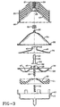
- a first fluid-damped mount embodying the invention is shown generally at 10 and comprises a housing or canister 12 which has an upper cylindrical member 14 and a lower cup member 15 joined together by means of clips 17 which form mechanical joints at flange 19, without requiring hydraulic seal capability. Further, the mount includes an upper compliance member 20 and a lower compliance member 21 having opposing respective internal surfaces 23,25. Both of the compliance members 20 and 21 are generally concave or hollowed so that the inner surfaces 23,25 define an inner chamber to receive and support a module 30 for containing damping fluid members are of elastomer e.g. rubber.
- the upper compliance member 20 meets multi-axis and dynamic requirements and has a size and geometry to meet the requirements of the particular vehicle with which it is used. It includes a central insert 27, with a threaded bore 29 on the external side for mounting a component to be supported, e.g. by way of a threaded stud or the like.
- the insert further has an inwardly-opening recess 28 which receives a fill cap 32 of the module 30. This fill cap could also be located at the equator of the module or at another convenient place.
- the insert 27 is made of a suitably non-deformable material, such as metal.
- the module 30 is a self-contained fluid-tight sealed module which comprises a top diaphragm member 34 with a peripheral sealing flange 35 and a seal port 36 (closable by means of the fill cap 32 or by other suitable means), and a bottom diaphragm 38 having a peripheral sealing flange 39.
- the module 30 further includes a divider plate 40 having a central tube hole 42: an inlet and outlet port connected by generally cylindrical longitudinally-extending tube walls 43 which, together with a stop cock member 52, form a fluid-flow regulating orifice or channel.
- the top diaphragm member defines a top fluid chamber of the module, while the bottom diaphragm member 38 includes a depression 47 with a recess 49 in a central raised portion, and a nipple or boss 50 which projects into said fluid chamber.
- the nipple 50 holds the stop cock member 52, which has flanges 53 received in the recess 49.
- the stop cock 52 has a waist section 55 of reduced diameter, to regulate the flow of the fluid through the orifice 42 of the divider plate 40, and extends through the orifice into or towards the upper fluid chamber.
- the lower diaphragm member further includes an elongate external boss 60 which projects axially down through an opening in the lower compliance member 21.
- the boss engages a compression spring 64 which rests in a recess in the lower housing member 15. This provides additional fluid-returning force.
- the circumferential flange 19 of the device incorporates the supporting flanges 66,67 of the top and bottom housing members respectively and the sealing flange portions 35,39 of the top and bottom diaphragms.
- the divider plate 40 has a peripheral portion 70 which is captured between the flanges 35,39 of the diaphragms.
- the peripheral portion 70 of the divider plate does not extend the full radial extent of the sealing flanges, so a seal is achieved around it between the top and bottom diaphragm members e.g. by adhesive or heat sealing. However, it extends sufficiently far into the sealed area to separate effectively the top and bottom chambers of the fluid-containing module.
- the clips 17 may comprise laterally extending projections from the bottom supporting flange 67 of the bottom housing member which are simply bent into position to trap the top supporting flange 66 of the upper housing.
- the construction has the advantage that neither the top and bottom compliance members, nor the top and bottom housing members, need form an air-tight or fluid-tight seal.
- the design of the top and bottom compliance members may be dedicated to damping vibrations and oscillations, without being restricted by needing to achieve a seal between the members.
- the module 30 is fluid-tight regardless of the distribution of forces on the members.
- an advantage is provided insofar as the module 30 for containing damping fluid may be assembled and filled in an environment different from that for the general assembly of the mount. With the role of fluid retainer being removed from the top and bottom compliance members, it is necessary only that they support the fluid-containing module 30 and provide resilient characteristics as needed for the specific vehicle.
- the present embodiment is designed for use with electrorheological fluid and therefore has a sensor component 80, operatively connected to a microprocessor 81, and including a plate member 83 which forms a circuit with a lead connected to the divider plate 40.
- the centre pin electrode (stop cock 52) and the divider plate electrode are.positioned to form a ring orifice within the central orifice 42.
- the pin electrode will move downward an equal or greater amount.
- the resulting relative motion between the centre pin and the divider plate electrode which simulates a "sliding plate” mechanism in the radial fluid.
- the waist section 55 of the stop cock 52 is an additional tuning mechanism to regulate fluid flow.
- the fluid chamber is designed so that as the top and bottom chambers are filled, air will be forced out through the fill port 36.
- An extension 46 in the lower diaphragm inhibits deflection of the stop cock member to prevent direct contact with the divider plate 40.
- the mount may act as a standard elastically-resilient mount.
- a voltage is applied to the electrode to increase the fluid viscosity and accordingly the damping properties of the mount.
- a ring orifice is formed by co-operation of a divider plate opening with a needle valve 85 operable by a servo hydraulic actuator using a microprocessor similar to the one shown for the first embodiment.
- external hydraulic drive chambers 87,88 can be driven upward or downward so as to change the relative location of the stop cock or obturating portion 90 of the needle valve 85.
- the hydraulic chambers 87,88 are defined by the bottom side of the lower diaphragm and a longitudinal opening in the bottom compliance member 21'.
- the upper and lower diaphragms of the fluid containing module are typically of a heat- or chemical-sealable polymer which is selected to have the required tensile, flex, elongation and fluid resistance properties. Specific examples include polyethylene and polypropylene.
- the upper and lower compliance members are of elastomer having the desired physical characteristics, and may be premoulded in halves for ease of assembly and to allow for greater internal detail.
- the mount may be assembled by first assembling the module with the internal divider plate in place. As has been previously discussed, it is advantageous to provide a fluid-tight seal such as a heat seal at the sealing flanges of the upper and lower diaphragm.
- the module may subsequently be filled with fluid such as by a fill and evacuation technique using the fill port 36. Once filled, the fluid package may be tested for fluid or air leaks. Further, this may be accomplished before assembly into the mount.
- the fluid-containing module may be assembled between the compliance members off-site.
- the present design also accommodates the assembly of the mount on site, insofar as the assembler does not need to bother with the fluid or with filling the mount. Further, the present design contributes to eliminating or at least reducing the two main causes of fluid malfunctions, leaks and air entrapment.
Landscapes
- Engineering & Computer Science (AREA)
- General Engineering & Computer Science (AREA)
- Mechanical Engineering (AREA)
- Combined Devices Of Dampers And Springs (AREA)
Claims (17)
- Dispositif de montage élastique à amortissement fluidique, dans lequel le fluide d'amortissement occupe une chambre d'amortissement définie adjacente à au moins un élément élastiquement déformable (20,21) du dispositif, afin d'amortir des déformations élastiques do celui-ci, la chambre d'amortissement comportant une paroi de diaphragme étanche au fluide (34,38) s'adaptant à l'élément élastiquement déformable (20,21), caractérisé en ce que la paroi de diaphragme (34,38) est une paroi d'un module étanche au fluide (30), dans lequel le fluide d'amortissement est contenu et qui a été rendue étanche préalablement avant l'assemblage contre l'élément élastiquement déformable (20,21).
- Dispositif de montage selon la revendication 1, dans lequel sont prévus deux éléments élastiquement déformables opposée (20,21) et la chambre d'amortissement est définie entre ceux-ci.
- Dispositif de montage selon la revendication 2, dans lequel la paroi de diaphragme (34,38) du module étanche au fluide (30) s'adapte aux deux éléments élastiquement déformables (20,21).
- Dispositif de montage selon l'une des revendications précédentes, dans lequel l'élément élastiquement déformable (20,21) dont au moins un est prévu est fixé dans un boîtier extérieur rigide (15,20).
- Dispositif de montage selon la revendication 4, dans lequel le boîtier extérieur rigide (15,20) est tubulaire, définissant une direction de déformation axiale du dispositif.
- Dispositif de montage selon l'une des revendications précédentes, dans lequel le module étanche au fluide (30) comprend un composant de régulation d'écoulement de fluide (40,42) comportant une ou plusieurs ouvertures ou canaux de commande de l'écoulement du fluide pour régler l'écoulement du fluide d'amortissement dans celui-ci.
- Dispositif de montage selon la revondication 6, dans lequel le composant de régulation de l'écoulement de fluide comprend une plaque de division (40) divisant la chambre d'amortissement en des première et deuxième chambres de fluide, les première et deuxième chambres de fluide étant reliées par un orifice restreint (42) de la plaque de division (40) constituant une ouverture de commande de l'écoulement du fluide.
- Dispositif de montage selon la revendication 6 ou la revendication 7, dans lequel le module étanche au fluide (30) comprend un obturateur (52) qui est déplaçable pour faire varier l'étendue d'une ou de plusieurs ouvertures ou canaux de commande de l'écoulement du fluide.
- Dispositif de montage selon la revendication 8, comprenant des chambres d'entraînement hydraulique externes (87,88) pour entraîner de manière contrôlée ledit élément élastiquement déformable (38), pour porter l'obturateur (52), pour régler de manière commandée l'étendue d'une ou de plusieurs ouvertures ou canaux de commande de l'écoulement du fluide.
- Dispositif de montage selon l'une des revendications 6 à 9, dans lequel le fluide d'amortissement est un fluide électro-rhéologique, et le dispositif de montage comprend un moyen pour appliquer une tension afin de régler la viscosité du fluide électro-rhéologique.
- Dispositif de montage selon l'une des revendications précédentes, dans lequel le module étanche au fluide (30) comprend un élément de diaphragme supérieur (34) et un élément de diaphragme inférieur (38), les éléments de diaphragme (34,38) ayant des rebords d'étanchéité périphériques respectifs (35,39) autour desquels ils sont soudés l'un à l'autre.
- Dispositif de montage selon l'une des revendications précédentes, dans lequel le module étanche au fluide (30) a une saillie de localisation (32,36;35,39) en prise avec une pièce adjacente (28;66,67) du dispositif de montage pour maintenir le module étanche au fluide (30) en position dans le dispositif de montage.
- Dispositif de montage selon la revendication 12 dépendant de la revendication 4, dans lequel ladite saillie de localisation est serrée entre les premier et deuxième composants (15,20) du boîtier extérieur rigide du dispositif de montage.
- Procédé pour assembler un dispositif de montage élastique à amortissement fluidique, dans lequel le fluide d'amortissement occupe une chambre d'amortissement définie adjacente à au moins un élément élastiquement déformable (20,21) du dispositif de montage pour amortir les déformations élastiques de celui-ci, la chambre d'amortissement comportant une paroi de diaphragme étanche au fluide (34,38) s'adaptant à l'élément élastiquement déformable (20,21), caractérisé par les étapes consistant à sceller préalablement le fluide d'amortissement dans un module étanche au fluide (30) comportant la paroi de diaphragme déformable (34,38) et à assembler le dispositif de montage pour adopter la paroi de diaphragme (34,38) du module pré-scellé, étanche au fluide à l'éLément élastiquement déformable (20,21).
- Procédé selon la revendication 14, dans lequel le dispositif de montage comporte deux éléments élastiquement déformables opposés (20,21), et le module pré-scellé étanche au fluide est positionné entre ceux-ci lors de l'assemblage du dispositif de montage.
- Procédé selon la revendication 14 ou la revendication 15, dans lequel le module pré-scellé étanche au fluide (30) est testé en vue de fuites de fluide et/ou d'inclusions d'air avant qu'il soit installé dans le dispositif de montage.
- Procédé selon l'une des revendications 14 à 16, dans lequel le dispositif de montage est réalisé conformément à l'une des revendications 3 à 13.
Applications Claiming Priority (2)
| Application Number | Priority Date | Filing Date | Title |
|---|---|---|---|
| US87493092A | 1992-04-28 | 1992-04-28 | |
| US874930 | 1992-04-28 |
Publications (2)
| Publication Number | Publication Date |
|---|---|
| EP0568340A1 EP0568340A1 (fr) | 1993-11-03 |
| EP0568340B1 true EP0568340B1 (fr) | 1996-06-19 |
Family
ID=25364887
Family Applications (1)
| Application Number | Title | Priority Date | Filing Date |
|---|---|---|---|
| EP93303314A Expired - Lifetime EP0568340B1 (fr) | 1992-04-28 | 1993-04-28 | Supports élastiques à amortissement fluidique et montage de tels supports |
Country Status (6)
| Country | Link |
|---|---|
| US (2) | US5848782A (fr) |
| EP (1) | EP0568340B1 (fr) |
| JP (1) | JPH0727168A (fr) |
| KR (1) | KR960016091B1 (fr) |
| CA (1) | CA2094208A1 (fr) |
| DE (1) | DE69303223T2 (fr) |
Cited By (1)
| Publication number | Priority date | Publication date | Assignee | Title |
|---|---|---|---|---|
| DE102004039825A1 (de) * | 2004-08-16 | 2006-03-09 | Vibracoustic Gmbh & Co. Kg | Hydraulisch dämpfendes Lager |
Families Citing this family (32)
| Publication number | Priority date | Publication date | Assignee | Title |
|---|---|---|---|---|
| GB2316731B (en) * | 1996-07-29 | 2000-09-27 | Draftex Ind Ltd | Vibration damping assemblies |
| DE19652501C1 (de) * | 1996-12-17 | 1998-07-16 | Contitech Formteile Gmbh | Selbstschaltendes Hydrauliklager mit akustischer Abkopplung |
| DE19812837C2 (de) * | 1998-03-24 | 2000-02-24 | Mannesmann Boge Gmbh | Hydraulisch dämpfendes Motorlager |
| GB2342977A (en) * | 1998-10-23 | 2000-04-26 | Draftex Ind Ltd | Hydroelastic engine mount |
| DE19902493C2 (de) * | 1999-01-22 | 2001-02-01 | Freudenberg Carl Fa | Umschaltbares Zweikammer-Stützlager mit hydraulischer Dämpfung |
| JP3692815B2 (ja) * | 1999-02-05 | 2005-09-07 | 東海ゴム工業株式会社 | 流体封入式能動型防振装置 |
| JP3603651B2 (ja) * | 1999-03-09 | 2004-12-22 | 東海ゴム工業株式会社 | 流体封入式防振装置の製造方法 |
| EP1055839B1 (fr) * | 1999-05-27 | 2004-07-28 | Carl Freudenberg KG | Support amorti hydrauliquement |
| JP3663482B2 (ja) | 1999-05-27 | 2005-06-22 | 東洋ゴム工業株式会社 | 切替型液封入式防振装置 |
| US6435487B1 (en) * | 1999-07-12 | 2002-08-20 | Toyo Tire & Rubber Co., Ltd. | Liquid sealed type vibration isolator |
| US6447871B1 (en) | 1999-09-27 | 2002-09-10 | The Aerospace Corporation | Composite materials with embedded machines |
| US6830793B2 (en) | 1999-09-27 | 2004-12-14 | The Aerospace Corporation | Composite damping material |
| JP3353082B2 (ja) * | 2000-02-01 | 2002-12-03 | 東洋ゴム工業株式会社 | 切替型液封入式防振装置 |
| DE10016705B4 (de) * | 2000-04-05 | 2004-05-06 | Contitech Vibration Control Gmbh | Befestigungselement zur elastischen Lagerung von Baugruppen |
| US6378851B1 (en) | 2000-10-25 | 2002-04-30 | Lord Corporation | Fluid and elastomer apparatus with discrete volume compensator and secondary compliance |
| DE10307680A1 (de) * | 2003-02-21 | 2004-09-30 | Carl Freudenberg Kg | Hydrolager |
| US9026578B2 (en) | 2004-05-14 | 2015-05-05 | Microsoft Corporation | Systems and methods for persisting data between web pages |
| US7461726B2 (en) * | 2005-02-25 | 2008-12-09 | The Aerospace Corporation | Force diversion apparatus and methods |
| US7367898B2 (en) * | 2005-02-25 | 2008-05-06 | The Aerospace Corporation | Force diversion apparatus and methods and devices including the same |
| US7347437B1 (en) * | 2006-09-28 | 2008-03-25 | Gm Global Technology Operations, Inc. | Damper assembly |
| JP2009079678A (ja) * | 2007-09-26 | 2009-04-16 | Tokai Rubber Ind Ltd | 防振装置及び該防振装置の製造方法 |
| WO2010071649A1 (fr) | 2008-12-18 | 2010-06-24 | Bell Helicopter Textron Inc. | Procédé et dispositif pour une isolation améliorée aux vibrations |
| CN102405359B (zh) | 2009-03-12 | 2015-02-11 | 贝尔直升机泰克斯特龙公司 | 用于改进振动隔离的方法及设备 |
| GB2480695B (en) * | 2010-05-28 | 2012-04-25 | Dtr Vms Ltd | Hydraulically damped mounting device |
| CN102345699A (zh) * | 2011-06-20 | 2012-02-08 | 贺劼 | 一种内置副气室加节流塞的变动刚度复合空气弹簧 |
| CN102401058A (zh) * | 2011-06-21 | 2012-04-04 | 贺劼 | 一种填充物静刚度调节和节流动刚度调节的空气弹簧 |
| US8882091B2 (en) | 2011-11-11 | 2014-11-11 | Textron Innovations Inc. | Vibration isolation system |
| US9194452B2 (en) | 2012-10-31 | 2015-11-24 | The Aerospace Corporation | High stiffness vibration damping apparatus, methods and systems |
| US10145443B2 (en) | 2015-01-26 | 2018-12-04 | Itt Manufacturing Enterprises Llc | Compliant elastomeric shock absorbing apparatus |
| KR102400472B1 (ko) * | 2017-08-24 | 2022-05-20 | 현대자동차주식회사 | 엔진 마운트 |
| KR102441401B1 (ko) | 2017-10-16 | 2022-09-07 | 현대자동차주식회사 | 단방향 댐핑 멤브레인이 구비된 유체봉입마운트 |
| CN110397697B (zh) | 2018-09-10 | 2021-02-23 | 北京京西重工有限公司 | 液压悬置装置及分离件 |
Family Cites Families (26)
| Publication number | Priority date | Publication date | Assignee | Title |
|---|---|---|---|---|
| US1288447A (en) * | 1917-12-04 | 1918-12-17 | United Air Spring Company Of Arizona | Pneumatic support. |
| FR1590701A (fr) * | 1968-09-25 | 1970-04-20 | ||
| DE2215921A1 (de) * | 1972-04-01 | 1973-10-11 | Bilstein August Fa | Hydraulischer stossdaempfer |
| JPS5820745B2 (ja) * | 1978-01-23 | 1983-04-25 | 三菱重工業株式会社 | トレ−サヘツド |
| DE3167400D1 (en) * | 1980-05-09 | 1985-01-10 | Nissan Motor | Engine mounting for suspending engine relative to vehicle structure |
| JPS6134180Y2 (fr) * | 1981-01-07 | 1986-10-06 | ||
| DE3480187D1 (en) * | 1983-02-17 | 1989-11-23 | Honda Motor Co Ltd | Fluid-sealed engine mounting |
| US4560150A (en) * | 1983-11-25 | 1985-12-24 | Imperial Clevite Inc. | Dry viscous spring strut |
| US4555098A (en) * | 1983-11-25 | 1985-11-26 | Imperial Clevite Inc. | Self-stabilizing dry viscous spring damper |
| US4593891A (en) * | 1983-11-28 | 1986-06-10 | Kaisha Toyota Jidosha Kabushiki | Vibration-absorbing mounting device with hydraulic damping, especially for engines |
| DE3347274C2 (de) * | 1983-12-28 | 1987-02-26 | Lemförder Metallwaren AG, 2844 Lemförde | Hydraulischer Schwingungsdämpfer für elastische Stützlager in Kraftfahrzeugen |
| DE3347273C2 (de) * | 1983-12-28 | 1987-01-15 | Lemförder Metallwaren AG, 2844 Lemförde | Elastisches Stützlager mit einem hydraulischen Dämpfer |
| JPS6155427A (ja) * | 1984-08-27 | 1986-03-19 | Bridgestone Corp | 防振装置 |
| DE3441592A1 (de) * | 1984-11-14 | 1986-05-15 | Continental Gummi-Werke Ag, 3000 Hannover | Hydraulisch gedaempftes elastisches lager |
| DE3501112C2 (de) * | 1985-01-15 | 1986-12-04 | Fa. Carl Freudenberg, 6940 Weinheim | Motorlager |
| US4742998A (en) * | 1985-03-26 | 1988-05-10 | Barry Wright Corporation | Active vibration isolation system employing an electro-rheological fluid |
| FR2589208B1 (fr) * | 1985-10-28 | 1989-12-22 | Hutchinson Sa | Perfectionnements aux supports antivibratoires hydrauliques |
| FR2590344B1 (fr) * | 1985-11-18 | 1989-11-17 | Hutchinson Sa | Perfectionnements aux amortisseurs hydrauliques |
| GB8709064D0 (en) * | 1986-04-28 | 1987-05-20 | Varian Associates | Wafer handling arm |
| DE3705579C2 (de) * | 1987-02-21 | 1995-11-02 | Bosch Gmbh Robert | Verstellbares Motorlager |
| JPH0260902A (ja) * | 1988-08-25 | 1990-03-01 | Natoko Paint Kk | 真球状重合体紛末の製造方法 |
| JPH0781605B2 (ja) * | 1989-02-01 | 1995-09-06 | 東海ゴム工業株式会社 | 電気粘性流体使用装置 |
| US4991826A (en) * | 1989-10-02 | 1991-02-12 | General Motors Corporation | Hydraulic mount with voltage controlled fluid |
| DE4027808A1 (de) * | 1990-09-01 | 1992-04-30 | Boge Ag | Elastisches gummilager |
| DE4106838A1 (de) * | 1991-03-04 | 1992-09-10 | Metzeler Gimetall Ag | Daempfendes aggregatlager |
| JPH06335838A (ja) * | 1993-05-28 | 1994-12-06 | Nippei Toyama Corp | 長尺ワーク加工装置 |
-
1993
- 1993-04-16 CA CA002094208A patent/CA2094208A1/fr not_active Abandoned
- 1993-04-26 KR KR1019930006999A patent/KR960016091B1/ko not_active Expired - Fee Related
- 1993-04-28 JP JP5125290A patent/JPH0727168A/ja active Pending
- 1993-04-28 EP EP93303314A patent/EP0568340B1/fr not_active Expired - Lifetime
- 1993-04-28 DE DE69303223T patent/DE69303223T2/de not_active Expired - Fee Related
- 1993-11-24 US US08/158,713 patent/US5848782A/en not_active Expired - Fee Related
-
1994
- 1994-10-26 US US08/329,398 patent/US6126153A/en not_active Expired - Fee Related
Cited By (2)
| Publication number | Priority date | Publication date | Assignee | Title |
|---|---|---|---|---|
| DE102004039825A1 (de) * | 2004-08-16 | 2006-03-09 | Vibracoustic Gmbh & Co. Kg | Hydraulisch dämpfendes Lager |
| DE102004039825B4 (de) * | 2004-08-16 | 2010-10-14 | Carl Freudenberg Kg | Hydraulisch dämpfendes Lager |
Also Published As
| Publication number | Publication date |
|---|---|
| DE69303223D1 (de) | 1996-07-25 |
| JPH0727168A (ja) | 1995-01-27 |
| US5848782A (en) | 1998-12-15 |
| DE69303223T2 (de) | 1996-11-28 |
| US6126153A (en) | 2000-10-03 |
| CA2094208A1 (fr) | 1993-10-29 |
| KR930021972A (ko) | 1993-11-23 |
| KR960016091B1 (ko) | 1996-11-27 |
| EP0568340A1 (fr) | 1993-11-03 |
Similar Documents
| Publication | Publication Date | Title |
|---|---|---|
| EP0568340B1 (fr) | Supports élastiques à amortissement fluidique et montage de tels supports | |
| US5170998A (en) | Fluid-filled elastic mount having means for controlling elastic deformation of flexible diaphragm(s) defining equilibrium chamber(s) | |
| EP0440260B1 (fr) | Support élastique, rempli avec un liquide, à deux orifices utilisés sélectivement pour diminuer ou isoler des vibrations dans des gammes de fréquence différentes | |
| US4790520A (en) | Vibration insulating device with flexible diaphragm between radially outer gas chamber and radially inner liquid chamber | |
| JP2510903B2 (ja) | 流体封入式マウント装置およびその製造方法 | |
| JP2693434B2 (ja) | サスペンション用減衰力発生装置およびそれの作動制御装置 | |
| US5183243A (en) | Fluid-filled elastic mount having caulked portion for sealing off fluid chamber | |
| US5215293A (en) | Fluid-filled elastic mount having double-layered flexible membrane separating fluid chamber and vacuum-receiving chamber | |
| US4838529A (en) | Liquid-filled vibration isolating devices | |
| JPH0564553U (ja) | 流体弾性式エンジンマウントおよび振動絶縁装置 | |
| JP3603651B2 (ja) | 流体封入式防振装置の製造方法 | |
| US6598865B1 (en) | Fluid-filled vibration damping device | |
| JPH0633229Y2 (ja) | 流体封入式マウント装置 | |
| JPH05118375A (ja) | 流体封入式マウント装置 | |
| JPH10227328A (ja) | 液体封入式マウント及びその組立方法 | |
| JP2000274480A (ja) | 流体封入式防振装置 | |
| JPH04321833A (ja) | 流体封入式マウント装置 | |
| JP3487129B2 (ja) | 空気圧制御型流体封入式防振装置 | |
| JP2657550B2 (ja) | 流体封入式マウント装置 | |
| JPH0788871B2 (ja) | 流体封入式筒型マウント装置 | |
| JP3838280B2 (ja) | 液体封入式エンジンマウント | |
| JPH01199031A (ja) | 防振装置の作動制御装置 | |
| JP4341933B2 (ja) | 液封防振装置 | |
| JPH11117987A (ja) | 液体封入式防振装置 | |
| JP2814881B2 (ja) | 流体封入式マウント用仕切部材 |
Legal Events
| Date | Code | Title | Description |
|---|---|---|---|
| PUAI | Public reference made under article 153(3) epc to a published international application that has entered the european phase |
Free format text: ORIGINAL CODE: 0009012 |
|
| AK | Designated contracting states |
Kind code of ref document: A1 Designated state(s): DE FR GB IT |
|
| 17P | Request for examination filed |
Effective date: 19931214 |
|
| 17Q | First examination report despatched |
Effective date: 19941208 |
|
| GRAH | Despatch of communication of intention to grant a patent |
Free format text: ORIGINAL CODE: EPIDOS IGRA |
|
| GRAA | (expected) grant |
Free format text: ORIGINAL CODE: 0009210 |
|
| AK | Designated contracting states |
Kind code of ref document: B1 Designated state(s): DE FR GB IT |
|
| REF | Corresponds to: |
Ref document number: 69303223 Country of ref document: DE Date of ref document: 19960725 |
|
| ITF | It: translation for a ep patent filed | ||
| ET | Fr: translation filed | ||
| PLBE | No opposition filed within time limit |
Free format text: ORIGINAL CODE: 0009261 |
|
| STAA | Information on the status of an ep patent application or granted ep patent |
Free format text: STATUS: NO OPPOSITION FILED WITHIN TIME LIMIT |
|
| PG25 | Lapsed in a contracting state [announced via postgrant information from national office to epo] |
Ref country code: GB Effective date: 19970428 |
|
| 26N | No opposition filed | ||
| GBPC | Gb: european patent ceased through non-payment of renewal fee |
Effective date: 19970428 |
|
| PG25 | Lapsed in a contracting state [announced via postgrant information from national office to epo] |
Ref country code: FR Free format text: LAPSE BECAUSE OF NON-PAYMENT OF DUE FEES Effective date: 19971231 |
|
| PG25 | Lapsed in a contracting state [announced via postgrant information from national office to epo] |
Ref country code: DE Free format text: LAPSE BECAUSE OF NON-PAYMENT OF DUE FEES Effective date: 19980101 |
|
| REG | Reference to a national code |
Ref country code: FR Ref legal event code: ST |
|
| PG25 | Lapsed in a contracting state [announced via postgrant information from national office to epo] |
Ref country code: IT Free format text: LAPSE BECAUSE OF NON-PAYMENT OF DUE FEES;WARNING: LAPSES OF ITALIAN PATENTS WITH EFFECTIVE DATE BEFORE 2007 MAY HAVE OCCURRED AT ANY TIME BEFORE 2007. THE CORRECT EFFECTIVE DATE MAY BE DIFFERENT FROM THE ONE RECORDED. Effective date: 20050428 |