EP0567682B1 - Spritzgiessvorrichtung mit mehreren Formhöhlungen für optische Plattensubstrate - Google Patents
Spritzgiessvorrichtung mit mehreren Formhöhlungen für optische Plattensubstrate Download PDFInfo
- Publication number
- EP0567682B1 EP0567682B1 EP92107456A EP92107456A EP0567682B1 EP 0567682 B1 EP0567682 B1 EP 0567682B1 EP 92107456 A EP92107456 A EP 92107456A EP 92107456 A EP92107456 A EP 92107456A EP 0567682 B1 EP0567682 B1 EP 0567682B1
- Authority
- EP
- European Patent Office
- Prior art keywords
- resin
- molding apparatus
- injection molding
- optical disk
- nozzles
- Prior art date
- Legal status (The legal status is an assumption and is not a legal conclusion. Google has not performed a legal analysis and makes no representation as to the accuracy of the status listed.)
- Expired - Lifetime
Links
Images
Classifications
-
- B—PERFORMING OPERATIONS; TRANSPORTING
- B29—WORKING OF PLASTICS; WORKING OF SUBSTANCES IN A PLASTIC STATE IN GENERAL
- B29C—SHAPING OR JOINING OF PLASTICS; SHAPING OF MATERIAL IN A PLASTIC STATE, NOT OTHERWISE PROVIDED FOR; AFTER-TREATMENT OF THE SHAPED PRODUCTS, e.g. REPAIRING
- B29C45/00—Injection moulding, i.e. forcing the required volume of moulding material through a nozzle into a closed mould; Apparatus therefor
- B29C45/17—Component parts, details or accessories; Auxiliary operations
- B29C45/26—Moulds
- B29C45/263—Moulds with mould wall parts provided with fine grooves or impressions, e.g. for record discs
-
- B—PERFORMING OPERATIONS; TRANSPORTING
- B29—WORKING OF PLASTICS; WORKING OF SUBSTANCES IN A PLASTIC STATE IN GENERAL
- B29C—SHAPING OR JOINING OF PLASTICS; SHAPING OF MATERIAL IN A PLASTIC STATE, NOT OTHERWISE PROVIDED FOR; AFTER-TREATMENT OF THE SHAPED PRODUCTS, e.g. REPAIRING
- B29C45/00—Injection moulding, i.e. forcing the required volume of moulding material through a nozzle into a closed mould; Apparatus therefor
- B29C45/17—Component parts, details or accessories; Auxiliary operations
- B29C45/20—Injection nozzles
- B29C45/22—Multiple nozzle systems
-
- B—PERFORMING OPERATIONS; TRANSPORTING
- B29—WORKING OF PLASTICS; WORKING OF SUBSTANCES IN A PLASTIC STATE IN GENERAL
- B29C—SHAPING OR JOINING OF PLASTICS; SHAPING OF MATERIAL IN A PLASTIC STATE, NOT OTHERWISE PROVIDED FOR; AFTER-TREATMENT OF THE SHAPED PRODUCTS, e.g. REPAIRING
- B29C45/00—Injection moulding, i.e. forcing the required volume of moulding material through a nozzle into a closed mould; Apparatus therefor
- B29C45/17—Component parts, details or accessories; Auxiliary operations
- B29C45/26—Moulds
- B29C45/263—Moulds with mould wall parts provided with fine grooves or impressions, e.g. for record discs
- B29C2045/2651—Moulds with mould wall parts provided with fine grooves or impressions, e.g. for record discs using a plurality of mould cavities
-
- Y—GENERAL TAGGING OF NEW TECHNOLOGICAL DEVELOPMENTS; GENERAL TAGGING OF CROSS-SECTIONAL TECHNOLOGIES SPANNING OVER SEVERAL SECTIONS OF THE IPC; TECHNICAL SUBJECTS COVERED BY FORMER USPC CROSS-REFERENCE ART COLLECTIONS [XRACs] AND DIGESTS
- Y10—TECHNICAL SUBJECTS COVERED BY FORMER USPC
- Y10S—TECHNICAL SUBJECTS COVERED BY FORMER USPC CROSS-REFERENCE ART COLLECTIONS [XRACs] AND DIGESTS
- Y10S425/00—Plastic article or earthenware shaping or treating: apparatus
- Y10S425/81—Sound record
Definitions
- the present invention relates to an injection molding apparatus according to the precharacterizing part of claim 1.
- Such an injection molding apparatus is known from US-A-4 971 548.
- an optical disk substrate normally formed of transparent resin has a central hole 1 as shown in Fig. 2 regardless of the case that the substrate has an uneven surface by pits or it has a smooth surface without pits.
- the central hole 1 is adapted to be mounted to a rotary driving portion in an optical disk drive. It is required that the substrate surface around the central hole 1 is uniform in optical characteristics such as an index of double refraction. Therefore, in molding the optical disk substrate, it is obliged to provide an injection opening for injecting resin into a cavity of a mold at a position corresponding to the center of the optical disk substrate where the central hole thereof is to be formed. That is, it is necessary that the mold for the optical disk substrate is provided with a sprue for injecting the resin into every cavity.
- the optical disk substrate is molded normally one by one by using an injection molding apparatus.
- an injection molding apparatus for molding the optical disk substrate one by one is disadvantageous in mass productivity.
- Such a multi-cavity injection molding apparatus is generally constituted of a mold unit having a plurality of cavities for molding the optical disk substrates and an injection unit for supplying a molten resin to the mold unit.
- the mold unit is provided with a plurality of resin feeding passages respectively communicating with the plural cavities or respectively connected to a plurality of sprues corresponding to the plural cavities.
- the injection unit for supplying the molten resin to the mold unit is provided with a plurality of resin supplying sections or screw mechanisms for respectively supplying the molten resin under pressure to the plural sprues in the mold unit.
- the plural screw mechanisms are provided, special design and manufacture of the injection molding apparatus are required to cause an increase in cost.
- US-A-4 971 548 describes a known injection molding apparatus in accordance with the precharacterizing part of claim 1.
- Said known injection molding apparatus comprises a movable mold unit, a stationary mold unit and a stationary mold base plate which during the injection of the resin and the molding process is fixedly connected with the stationary mold unit and after the molding process is retracted therefrom.
- the plurality of nozzles are a part of said stationary mold base plate.
- An injection unit being specifically constructed and having a branched section comprising said nozzles at the formed end thereof, is not described in US-A-4 971 548.
- EP-A-0 177 991 discloses a single nozzle disposed on a movable injection unit.
- an injection molding apparatus comprises:
- the plural nozzles corresponding to the plural cavities in the mold unit are provided in the injection unit for supplying a molten resin. Accordingly, as compared with the case where the nozzles are provided in the mold unit, the structure and the construction of the injection molding apparatus can be simplified to thereby realize cost reduction and easy maintenance such as resin purging.
- the resin supplying section is singularly provided in the injection unit, and it is connected through a plurality of branches resin feeding passages to the plural nozzles. Accordingly, an increase in cost can be suppressed.
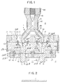
- FIG. 1 A preferred embodiment of the injection molding apparatus according to the present invention will now be described with reference to Fig. 1.
- the injection molding apparatus shown in Fig. 1 is of a vertical construction such that two optical disk substrates are molded in every molding cycle.
- Reference numeral 12 generally designates a mold unit which is constituted of two sets of fixed molds 51 and movable molds 52.
- Each fixed mold 51 is held by a holding ring 41 which is fixedly inserted in a through hole 31H formed through a side plate 31.
- each movable mold 52 is held by a holding ring 42 which is fixedly inserted in a through hole 32H formed through a side plate 32.
- Reference numeral 23 designates a separating surface or a parting surface of the mold unit 12.
- a mounting plate 50 is provided to mount the fixed molds 51 together with the side plate 31.
- the mounting plate 50 is formed with two through holes 50H, and the fixed molds 51 are respectively formed with two central through holes 51H which are respectively aligned to the two through holes 50H of the mounting plate 50.
- Two sprue bushes 15 are vertically movably inserted in the two through holes 50H of the mounting plate 50 and the two central through holes 51H of the fixed molds 51, respectively.
- Each sprue bush 15 is axially central formed with a sprue 14 opening at its lower end into the corresponding cavity 11 at a central position thereof.
- Each through hole 50H of the mounting plate 50 is widened at its upper end in diameter to form a recess 24, and each sprue bush 15 is correspondingly widened at its upper end in diameter to form a flange 15F.
- the flange 15F of each sprue bush 15 is received in the corresponding recess 24 so as to normally abut against a bottom surface of the recess 24. In this condition, a lower end of each sprue bush 15 is flush with an upper surface of the corresponding cavity 11.
- Two locating rings 20 are fixed by screws 20S to an upper surface of the mounting plate 50 along the outer circumferences of the respective recesses 24 of the mounting plate 50 so that an upper surface of the flange 15F of each sprue bush 15 may abut against a lower surface of the corresponding locating ring 20 when the sprue bush 15 is lifted.
- a fine spacing 25 is normally defined between the upper surface of the flange 15F of each sprue bush 15 and the lower surface of the corresponding locating ring 20, and when each sprue bush 15 is lifted by the fine spacing 25, the upper surface of the flange 15F of each sprue bush 15 comes into abutment against the lower surface of the corresponding locating ring 20, so that fine vertical movement of each sprue bush 15 corresponding to the fine spacing 25 is permitted, and escape of each sprue bush 15 from the corresponding recess 24 is prevented by the corresponding locating ring 20.
- a platen 21 is fixed by screws 62 to the mounting plate 50.
- the platen 21 is formed with a nest locating hole 21H, and a nest 71 is fixedly located in the nest locating hole 21H.
- the nest 71 is formed with two receiving holes 71H for respectively receiving the two locating rings 20. Each locating ring 20 is fixedly received in the corresponding receiving hole 71H.
- Reference numeral 13 generally designates an injection unit which is constituted of a resin supplying section 19, a branched section 86 having two resin feeding passages 18, and an intermediate connecting section 88 for connecting the branched section 86 to the resin supplying section 19.
- the branched section 86 is provided at its formed ends with two nozzles 17 respectively communicating with the two resin feeding passages 18 and opening into the upper ends of the sprues 14.
- Each nozzle 17 is so located as to abut against the upper end of the corresponding sprue bush 15 and urge the same so that the lower end of each sprue 14 may become flush with the upper surface of the corresponding cavity 11.
- the resin supplying section 19 is constructed of a screw mechanism, and although not shown, a resin pellet such as polycarbonate or acrylic resin is supplied to the resin supplying section 19.
- the resin pellet thus supplied is molten by heating means 90 such as an electrical heater, and is agitated by rotation of the screw mechanism.
- the molten resin is supplied from the resin supplying section 19 by lowering the screw mechanism under hydraulic pressure, for example, and is fed through the intermediate connecting section 88 to the branched section 86. Then, the flow of the molten resin is branched into the two resin feeding passages 18, and is injected from the nozzles 17 through the sprues 14 into the cavities 11.
- Heating means 91 such as an electrical heater is provided on an outer circumference of the intermediate connecting section 88, and heating means 92 such as an electrical heater are also provided on outer circumferences of the formed portions of the branched section 86, so as to prevent solidification of the molten resin.
- Each movable mold 52 is formed with a central through hole 52H aligned to the central through hole 51H of the corresponding fixed mold 51.
- Two punches 16 are vertically movably inserted in the central through holes 52H of the movable molds 52, respectively.
- Each punch 16 is aligned to the corresponding sprue bush 15, and has a diameter equal to an outer diameter of the corresponding sprue bush 15. In molding the resin in each cavity 11, an upper end surface of the corresponding punch 16 is flush with a lower surface of the cavity 11.
- the resin is injected and charged into the cavities 11 to simultaneously form two disk-shaped optical disk substrates.
- each punch 16 is lifted to form a central hole through the optical disk substrate molded in the corresponding cavity 11.
- each sprue bush 15 is upwardly urged by the upper end surface of the corresponding punch 16 in the predetermined spacing 25 until the upper surface of the flange 15F of the sprue bush 15 comes into abutment against the lower surface of the corresponding locating ring 20. Accordingly, an upper end portion of each punch 16 can penetrate the central portion of the corresponding optical disk substrate over an entire thickness thereof.
- a central hole 1 as shown in Fig. 2 can be satisfactorily formed through each optical disk substrate.
- the injection molding apparatus described above is of a vertical construction and of a dual-cavity type, various changes and modifications may be made without departing from the scope of the present invention.
- the injection molding apparatus may be of a horizontal construction, or may be of a multi-cavity type having three or more cavities.
- the injection molding apparatus is so constructed as to mold a plurality of optical disk substrates in every molding cycle, thereby improving a mass productivity of the optical disk substrates.
- the nozzles 17 corresponding to the plural cavities 11 are provided in the injection unit 13, and they are formed as a part of the branched section 86 replaceably connected to the single resin supplying section 19. Accordingly, selection of single-cavity molding or multi-cavity molding may be attained by merely replacing the branched section 86 having the nozzles 17. In addition, since the nozzles 17 are provided in the injection unit 13 rather than the mold unit 12, the resin purging can be easily carried out.
- the platen 21 may be commonly used, and it is only necessary to replace the nest 71 in accordance with the number of the cavities 11 as well as the replacement of the branched section 86. Accordingly, compatibility and cost reduction of the injection molding apparatus can be achieved.
Landscapes
- Engineering & Computer Science (AREA)
- Manufacturing & Machinery (AREA)
- Mechanical Engineering (AREA)
- Moulds For Moulding Plastics Or The Like (AREA)
- Manufacturing Optical Record Carriers (AREA)
- Injection Moulding Of Plastics Or The Like (AREA)
Claims (4)
- Spritzgießvorrichtung mit- einer Formungseinheit (12), die mehrere Höhlungen (11) zum gleichzeitigen Gießen mehrerer optischer Plattensubstrate bildet und die folgendes aufweist: mehrere Einfüllhülsen (15), die den Höhlungen entsprechen und jeweils eine Einfüllöffnung (14) aufweisen, die in den zentralen Bereich der entsprechenden Höhlung (11) geöffnet ist, mehrere Austreiber (16), die den Einfüllhülsen (15) in Bezug auf die Höhlungen (11) gegenüberstehend so angeordnet sind, dass sie zentrale Bereiche der optischen Plattensubstrate nach dem Gießen durchdringen und so auf die Einfüllhülsen (15) drücken, dass zentrale Löcher (1) durch die optischen Plattensubstrate hindurch erzeugt werden, mehrere Positionierringe (20), die den Einfüllhülsen (15) entsprechen, um die Bewegung dieser Einfüllhülsen (15) auf einen vorbestimmten, kleinen Wert zu begrenzen, wenn die Austreiber (16) auf sie drücken, eine Platte (21) mit mehreren Aufnahmelöchern (71H) zum jeweiligen Aufnehmen der Positionierringe (20); und- mehreren Düsen (17) zum Einspritzen des von einem Harzversorgungsabschnitt (19) gelieferten geschmolzenen Harzes unter Druck durch die Einfüllöffnungen (14) in die jeweiligen Höhlungen (11);
dadurch gekennzeichnet, dass- die Formungseinheit (12) ferner einen Einsatz (71) aufweist, der austauschbar in der Platte (21) aufgenommen ist und mehrere Aufnahmelöcher zum jeweiligen Aufnehmen der Positionierringe (20) aufweist, wobei die Düsen (17) als Teile einer Einspritzeinheit (13) vorhanden sind, die durch den Harzzuführabschnitt (19) und einen verzweigten Abschnitt (18) gebildet wird, an deren Enden die Düsen (17) ausgebildet sind, wobei die Einspritzeinheit (13) aus der Formungseinheit (12) zurückziehbar beweglich ist, um eine kleine Bewegung der Einfüllhülsen gegen die Positionierringe (20) zu ermöglichen. - Spritzgießvorrichtung nach Anspruch 1, bei der die Einspritzeinheit (13) ferner mehrere Harzzuführkanäle (18) aufweist, um den Harzzuführabschnitt (19) mit den Düsen (17) zu verbinden.
- Spritzgießvorrichtung nach Anspruch 2, ferner mit einer Einrichtung (91, 92) zum Erwärmen des Harzzuführabschnitts (19) und der Harzzuführkanäle.
- Spritzgießvorrichtung nach Anspruch 1, bei der die Düsen (17) austauschbar mit dem Harzzuführabschnitt (19) verbunden sind.
Priority Applications (1)
| Application Number | Priority Date | Filing Date | Title |
|---|---|---|---|
| DE1992616219 DE69216219T2 (de) | 1992-04-30 | 1992-04-30 | Spritzgiessvorrichtung mit mehreren Formhöhlungen für optische Plattensubstrate |
Applications Claiming Priority (2)
| Application Number | Priority Date | Filing Date | Title |
|---|---|---|---|
| JP2-417125A JP3005299B2 (ja) | 1990-12-28 | 光学ディスク基板の複数個取り射出成型装置 | |
| HK98106503.0A HK1007293B (en) | 1998-06-24 | Multi-cavity injection molding apparatus for optical disk substrates |
Publications (2)
| Publication Number | Publication Date |
|---|---|
| EP0567682A1 EP0567682A1 (de) | 1993-11-03 |
| EP0567682B1 true EP0567682B1 (de) | 1996-12-27 |
Family
ID=26316733
Family Applications (1)
| Application Number | Title | Priority Date | Filing Date |
|---|---|---|---|
| EP92107456A Expired - Lifetime EP0567682B1 (de) | 1990-12-28 | 1992-04-30 | Spritzgiessvorrichtung mit mehreren Formhöhlungen für optische Plattensubstrate |
Country Status (3)
| Country | Link |
|---|---|
| US (1) | US5238393A (de) |
| EP (1) | EP0567682B1 (de) |
| AT (1) | AT402278B (de) |
Families Citing this family (7)
| Publication number | Priority date | Publication date | Assignee | Title |
|---|---|---|---|---|
| NL1010869C2 (nl) * | 1998-12-22 | 2000-06-30 | Axxicon Moulds Eindhoven Bv | Meervoudige spuitgieteenheid. |
| US6372175B1 (en) | 1999-09-17 | 2002-04-16 | General Electric Company | Resin pellets for injection molding |
| US6488680B1 (en) * | 2000-04-27 | 2002-12-03 | Medtronic, Inc. | Variable length electrodes for delivery of irrigated ablation |
| US6729870B2 (en) | 2001-11-06 | 2004-05-04 | Imation Corp. | Multi-cavity optical disc mold |
| US6984232B2 (en) * | 2003-01-17 | 2006-01-10 | St. Jude Medical, Daig Division, Inc. | Ablation catheter assembly having a virtual electrode comprising portholes |
| US7255555B2 (en) * | 2004-05-03 | 2007-08-14 | Mold-Masters Limited | Small pitch molding manifold |
| US10449706B2 (en) | 2014-11-17 | 2019-10-22 | Husky Injection Molding Systems Ltd. | Hot runner nozzle with a gate pressure equalizer |
Family Cites Families (16)
| Publication number | Priority date | Publication date | Assignee | Title |
|---|---|---|---|---|
| CH400553A (de) * | 1962-12-11 | 1965-10-15 | Ankerwerk Gebrueder Goller | Spritzgiessmaschine zur Herstellung von Teilen aus vernetzenden Kunst- oder Naturstoffen |
| US3568256A (en) * | 1968-07-15 | 1971-03-09 | J & J Machine Co Inc | Plastic feeder head |
| US4121740A (en) * | 1977-08-19 | 1978-10-24 | Chicago Rawhide Manufacturing Company | Injector head for injection molding machine |
| US4185955A (en) * | 1977-10-31 | 1980-01-29 | Mca Disco-Vision, Inc. | Apparatus for replicating centrally apertured video disc records |
| DE2938832A1 (de) * | 1979-09-26 | 1981-04-09 | EWIKON Entwicklung und Konstruktion GmbH & Co KG, 4900 Herford | Vorrichtung mit einem heisskanalsystem zum zufuehren einer kunststoffschmelze zu einer spritzgussform |
| IT1140636B (it) * | 1980-02-18 | 1986-10-01 | Francesco Colombi | Testata porticolarmente per pressa ad iniezione per materie termoplastiche |
| JPS59230731A (ja) * | 1983-06-14 | 1984-12-25 | Meiki Co Ltd | 中心部を開口した薄肉円盤の射出成形装置 |
| DE3423254C2 (de) * | 1983-09-29 | 1994-06-01 | Ewikon Entwicklung Konstr | Heißkanalwerkzeug zum Zuführen einer Kunststoffschmelze zu einer Spritzgießform |
| JPS60220720A (ja) * | 1984-04-18 | 1985-11-05 | Sankyo Kasei Kk | 射出成形機 |
| NL8501893A (nl) * | 1984-09-07 | 1986-04-01 | Nagron Precision Tooling | Spuitgietmatrijs met inzetstuk en spuitgietinrichting daarvoor. |
| JPS61100426A (ja) * | 1984-10-24 | 1986-05-19 | Matsushita Electric Ind Co Ltd | 光学デイスク成形金型 |
| US4828769A (en) * | 1986-05-05 | 1989-05-09 | Galic/Maus Ventures | Method for injection molding articles |
| NL8701499A (nl) * | 1987-06-26 | 1989-01-16 | Philips Nv | Spuitvorminrichting voor het vervaardigen van informatieplaten uit kunststof, alsmede werkwijze voor het vervaardigen van informatieplaten uit kunststof met een spuitvorminrichting. |
| JP2642158B2 (ja) * | 1988-08-16 | 1997-08-20 | 住友重機械工業株式会社 | 光ディスク基板成形用金型 |
| JPH0675892B2 (ja) * | 1988-09-01 | 1994-09-28 | 株式会社名機製作所 | ディスク用成形型 |
| US5069840A (en) * | 1990-02-16 | 1991-12-03 | Husky Injection Molding Systems Ltd. | Molding plastic articles |
-
1991
- 1991-12-27 US US07/816,393 patent/US5238393A/en not_active Expired - Lifetime
- 1991-12-27 AT AT0256591A patent/AT402278B/de not_active IP Right Cessation
-
1992
- 1992-04-30 EP EP92107456A patent/EP0567682B1/de not_active Expired - Lifetime
Also Published As
| Publication number | Publication date |
|---|---|
| HK1007293A1 (en) | 1999-04-09 |
| EP0567682A1 (de) | 1993-11-03 |
| JPH05305625A (ja) | 1993-11-19 |
| AT402278B (de) | 1997-03-25 |
| ATA256591A (de) | 1996-08-15 |
| US5238393A (en) | 1993-08-24 |
Similar Documents
| Publication | Publication Date | Title |
|---|---|---|
| US4340353A (en) | Hot sprue valve assembly for an injection molding machine | |
| CA1168408A (en) | Hot sprue valve assembly for an injection molding machine | |
| WO1990014205A1 (en) | Collapsible core for molding closure cap with segmented threads | |
| EP0567682B1 (de) | Spritzgiessvorrichtung mit mehreren Formhöhlungen für optische Plattensubstrate | |
| US5593710A (en) | Mold capable of changing a set position of a stamper plate | |
| US5693348A (en) | Disc molding die | |
| HK1007293B (en) | Multi-cavity injection molding apparatus for optical disk substrates | |
| CN209521218U (zh) | 一种塑料转子注塑模具 | |
| JP3008392B2 (ja) | 光ディスク用成形機 | |
| JP3005299B2 (ja) | 光学ディスク基板の複数個取り射出成型装置 | |
| KR100232820B1 (ko) | 슬라이드코아를 이용한 사출 성형 금형 및 사출방법 | |
| JP2002347085A (ja) | 射出成形金型 | |
| JP2001009875A (ja) | 射出成形金型 | |
| US5773040A (en) | Disc molding die | |
| JP3201572B2 (ja) | ホットランナを有する射出成形装置及び金型交換方法 | |
| CN220008643U (zh) | 可快速换模的注塑模具 | |
| CN220362932U (zh) | 一种注塑模具顶出装置的保护结构 | |
| JP3427561B2 (ja) | 金型装置 | |
| KR100225401B1 (ko) | 밀핀자국이 없는 사출 성형 금형 | |
| JP2968395B2 (ja) | 射出成形機の金型交換装置 | |
| JPH0541860Y2 (de) | ||
| US20020054931A1 (en) | Top mold of injection molding machine | |
| KR0137918Y1 (ko) | 몰드금형의 런너 회전방지 구조 | |
| KR900000992Y1 (ko) | 아웃서트 성형용 이중면접 금형장치 | |
| DE69216219T2 (de) | Spritzgiessvorrichtung mit mehreren Formhöhlungen für optische Plattensubstrate |
Legal Events
| Date | Code | Title | Description |
|---|---|---|---|
| PUAI | Public reference made under article 153(3) epc to a published international application that has entered the european phase |
Free format text: ORIGINAL CODE: 0009012 |
|
| AK | Designated contracting states |
Kind code of ref document: A1 Designated state(s): DE FR GB NL |
|
| 17P | Request for examination filed |
Effective date: 19940331 |
|
| 17Q | First examination report despatched |
Effective date: 19950619 |
|
| GRAG | Despatch of communication of intention to grant |
Free format text: ORIGINAL CODE: EPIDOS AGRA |
|
| GRAH | Despatch of communication of intention to grant a patent |
Free format text: ORIGINAL CODE: EPIDOS IGRA |
|
| GRAH | Despatch of communication of intention to grant a patent |
Free format text: ORIGINAL CODE: EPIDOS IGRA |
|
| GRAA | (expected) grant |
Free format text: ORIGINAL CODE: 0009210 |
|
| AK | Designated contracting states |
Kind code of ref document: B1 Designated state(s): DE FR GB NL |
|
| REF | Corresponds to: |
Ref document number: 69216219 Country of ref document: DE Date of ref document: 19970206 |
|
| ET | Fr: translation filed | ||
| PLBE | No opposition filed within time limit |
Free format text: ORIGINAL CODE: 0009261 |
|
| STAA | Information on the status of an ep patent application or granted ep patent |
Free format text: STATUS: NO OPPOSITION FILED WITHIN TIME LIMIT |
|
| 26N | No opposition filed | ||
| REG | Reference to a national code |
Ref country code: GB Ref legal event code: IF02 |
|
| PGFP | Annual fee paid to national office [announced via postgrant information from national office to epo] |
Ref country code: FR Payment date: 20110510 Year of fee payment: 20 Ref country code: DE Payment date: 20110421 Year of fee payment: 20 |
|
| PGFP | Annual fee paid to national office [announced via postgrant information from national office to epo] |
Ref country code: NL Payment date: 20110426 Year of fee payment: 20 Ref country code: GB Payment date: 20110421 Year of fee payment: 20 |
|
| REG | Reference to a national code |
Ref country code: DE Ref legal event code: R071 Ref document number: 69216219 Country of ref document: DE |
|
| REG | Reference to a national code |
Ref country code: DE Ref legal event code: R071 Ref document number: 69216219 Country of ref document: DE |
|
| REG | Reference to a national code |
Ref country code: NL Ref legal event code: V4 Effective date: 20120430 |
|
| REG | Reference to a national code |
Ref country code: GB Ref legal event code: PE20 Expiry date: 20120429 |
|
| PG25 | Lapsed in a contracting state [announced via postgrant information from national office to epo] |
Ref country code: DE Free format text: LAPSE BECAUSE OF EXPIRATION OF PROTECTION Effective date: 20120501 |
|
| PG25 | Lapsed in a contracting state [announced via postgrant information from national office to epo] |
Ref country code: GB Free format text: LAPSE BECAUSE OF EXPIRATION OF PROTECTION Effective date: 20120429 |