EP0566907B1 - Elektrolyseapparat mit Partikelkathoden - Google Patents
Elektrolyseapparat mit Partikelkathoden Download PDFInfo
- Publication number
- EP0566907B1 EP0566907B1 EP93105299A EP93105299A EP0566907B1 EP 0566907 B1 EP0566907 B1 EP 0566907B1 EP 93105299 A EP93105299 A EP 93105299A EP 93105299 A EP93105299 A EP 93105299A EP 0566907 B1 EP0566907 B1 EP 0566907B1
- Authority
- EP
- European Patent Office
- Prior art keywords
- cathode
- drums
- electrolyzer according
- drum
- electrolyzer
- Prior art date
- Legal status (The legal status is an assumption and is not a legal conclusion. Google has not performed a legal analysis and makes no representation as to the accuracy of the status listed.)
- Expired - Lifetime
Links
Images

Classifications
-
- C—CHEMISTRY; METALLURGY
- C25—ELECTROLYTIC OR ELECTROPHORETIC PROCESSES; APPARATUS THEREFOR
- C25C—PROCESSES FOR THE ELECTROLYTIC PRODUCTION, RECOVERY OR REFINING OF METALS; APPARATUS THEREFOR
- C25C7/00—Constructional parts, or assemblies thereof, of cells; Servicing or operating of cells
- C25C7/002—Constructional parts, or assemblies thereof, of cells; Servicing or operating of cells of cells comprising at least an electrode made of particles
-
- C—CHEMISTRY; METALLURGY
- C02—TREATMENT OF WATER, WASTE WATER, SEWAGE, OR SLUDGE
- C02F—TREATMENT OF WATER, WASTE WATER, SEWAGE, OR SLUDGE
- C02F1/00—Treatment of water, waste water, or sewage
- C02F1/46—Treatment of water, waste water, or sewage by electrochemical methods
- C02F1/461—Treatment of water, waste water, or sewage by electrochemical methods by electrolysis
- C02F1/46104—Devices therefor; Their operating or servicing
- C02F1/46109—Electrodes
- C02F1/46114—Electrodes in particulate form or with conductive and/or non conductive particles between them
-
- C—CHEMISTRY; METALLURGY
- C02—TREATMENT OF WATER, WASTE WATER, SEWAGE, OR SLUDGE
- C02F—TREATMENT OF WATER, WASTE WATER, SEWAGE, OR SLUDGE
- C02F1/00—Treatment of water, waste water, or sewage
- C02F1/46—Treatment of water, waste water, or sewage by electrochemical methods
- C02F1/461—Treatment of water, waste water, or sewage by electrochemical methods by electrolysis
- C02F1/467—Treatment of water, waste water, or sewage by electrochemical methods by electrolysis by electrochemical disinfection; by electrooxydation or by electroreduction
- C02F1/4676—Treatment of water, waste water, or sewage by electrochemical methods by electrolysis by electrochemical disinfection; by electrooxydation or by electroreduction by electroreduction
- C02F1/4678—Treatment of water, waste water, or sewage by electrochemical methods by electrolysis by electrochemical disinfection; by electrooxydation or by electroreduction by electroreduction of metals
Definitions
- the invention relates to an electrolysis apparatus which consists of at least two moving particle cathodes and at least one anode.
- Electrolysis devices of this type can be used in particular in electrolysis processes with particle electrodes, the volume of which constantly increases due to metal deposition.
- a typical area of application is electrochemical metal deposition from waste water; Particle electrodes are used to achieve favorable deposition conditions in electrolysis systems inhibited by mass transport due to their high specific surface area. These are particularly present at low depolarizer concentrations, as is the case with heavy metal removal from waste water.
- the invention is also applicable to continuous metal refining when metal granules are to be obtained.
- Kammel (Galvanotechnik 69 (1978) 687) uses a roller tube cell in which there is a bed of particles in a perforated drum surrounded by counter electrodes.
- a cell with continuous particle supply or removal is described in DD-PS 2 15 098.
- the discharge granules fall through a pipe to the bottom of an only slightly filled, inclined, cylindrical construction. The discharge takes place via screw conveyors.
- a device is described in DD-PS 2 89 902, which allows a drum filling degree greater than 0.5.
- the anode is outside the cathode drum and the current enters the drum from the front.
- the drum is driven from above via a V-belt or a gear.
- a plurality of particle cathodes and anodes arranged alternately one behind the other are provided.
- the cathodes are in cathode drums, which are arranged on an axis or shaft. Adjacent cathode drums are connected by channels, while an electrical contact device is located on the inside of a row cover and / or in at least one cathode drum.
- the electrolysis apparatus preferably consists of a plurality of cathode drums arranged alternately one behind the other with anode elements arranged between them, while in each cathode element there is a drum which is fastened at a common time and serves to receive the cathode particles. More than half of the cathode drums can be filled with cathode particles and catholyte liquid, adjacent cathode drums being connected by channels at a large distance from the axis of rotation and / or at a small distance from the axis of rotation of the drums in such a way that these channels vary in length Distance to the axis of rotation and / or a course winding around the axis of rotation - e.g. have a conical shape.
- Seals are located between the cell covers and the cathode drums on the shaft and on the drum jacket, which are located directly next to it, while there are centrally arranged, electrically conductive disks in the cathode drums, which, separately or electrically connected, form the cathode connection of the cell.
- the cathode connection of the cell can be connected on the inside.
- the anodes or cathodes can be electrically connected to the shaft, the anodic or cathodic current connection to the shaft being effected via a rotatable contact device.
- Axially wound baffles can be located on the inside of the wall of the cathode drum on the electrolyte inlet side, while feed and discharge devices for the cathode particles and on the cell covers or on the cell jacket feed and discharge devices for the electrolytes and discharge devices for the electrolysis gases can be attached to the electrolyte inlet side cell cover.
- the advantageous effect of the invention consists on the one hand in a gradual reduction in the depolarizer concentration of the electrolyte in the cathode drums connected in series.
- the electrolyte passes through each particle bed and, together with the catholyte gas, enters the next cathode drum via the connecting channels.
- the increase in volume of the cathode bed, caused by the desired metal deposition is compensated in such a way that the constant rotation of the cathode drums (analogous to the principle of communicating tubes) results in the same particle level in all drums via the connecting channels. If the particle level in the cell exceeds the height of the particle outlet nozzle, the excess particles get out of the cell through this.
- the particles are fractionated according to their size, so that there are preferably small particles on the electrolyte outlet side and large particles on the electrolyte inlet side.
- very fine-grained particle material can also be used. This favors the separation performance at low metal concentrations.
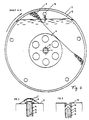
- FIG. 1 shows a longitudinal section through an electrolysis apparatus according to the invention, which has a cell housing consisting of two cell covers 1, 2 and a jacket tube 3; on an externally driven shaft 4, four cathode drums 13, which serve to receive the cathode particles 9, with anodes 10 arranged between them.
- Adjacent cathode drums are connected to one another by channels 16 in such a way that the catholyte, the cathode gas and the particles are exchanged through them.
- the connecting channels are designed so that, for a given direction of rotation, the large particles inevitably accumulating in the outer part of the drum (maximum radius) towards the side of the electrolyte inlet and the small particles collecting in the inner part of the drum (minimum radius) towards the side of the electrolyte outlet are transported.
- Possible embodiments of these connecting channels are on the outer surface of the drum at an angle to the axis of rotation diagonally attached nozzle 8, which in pairs by z. B. tubes 7 are connected to each other (Fig. 2) or attached between the side walls 14 of the cathode drums (Fig. 3).
- the transport through these channels takes place through a curved course in the longitudinal direction in such a way that the distance between the channel axis and the axis of rotation takes a maximum at a point between two drums and / or the direct line connecting the openings of a channel in both cathode drums with the axis of rotation at an angle forms.
- the channels With each drum rotation, the channels are filled once and emptied again. Different filling and emptying times result in the directed transport of the particles.
- the inside of the walls of the cathode drums consist of a diaphragm and / or an ion exchange membrane 15 and to achieve a high stability with a low electrolyte resistance between the anode and cathode bed on the outside of a coarse perforated plate 14.
- the wall of the outer on the electrolyte outlet side Cathode drum contains a porous layer 17, which allows electrolyte and cathode gas to flow through.
- the cathode drum located on the electrolyte inlet side is open towards the cell cover 1.
- the metal particles are kept both on the inner and on the outer part of the drum by low-wear seals, in the exemplary embodiment consisting of fixed glass rings 21 and resilient, rotating rings 22, from seals 20 (round or radial shaft seals) attached behind them.
- the remaining particle cathodes 9 are electrically connected to one another via the arranged therein Disks 6 cathodically polarized. With a direct cathodic connection of the disks in the cathode drums, the fixed contact plate is omitted. This has the advantage in the presence of high depolarizer concentrations, in which metallic deposits on the contact plate can disrupt long-term operation.
- the anodes are attached to anode rings 11, via the they are electrically connected to the shaft 4.
- the current is transferred to the shaft without a slip ring.
- Completely maintenance-free, closed mercury rotary transformers have proven successful as contact devices.
- the use of multi-channel rotary transformers is possible, or the power is connected from both sides of the shaft, in which case a hollow shaft must be used.
- the following table shows parameters and measured values of an exemplary embodiment: Number of cathode drums 5 Diameter of the cathode drums 250mm Width of the cathode drums 60mm Particle diameter 3mm Degree of drum filling 2/3 Drum speed 2min -1 electrolyte CuSo 4 / H z SO 4 Throughput l / h Current A Cu concentration inlet mg / l Cu concentration outlet mg / l 12.5 50 4800 1150 57.1 25th 1800 1325 15.4 50 1650 10th 24.6 20th 910 1 56.2 50 435 ⁇ 0.1 60.0 20th 135 ⁇ 0.1
Landscapes
- Chemical & Material Sciences (AREA)
- Organic Chemistry (AREA)
- Electrochemistry (AREA)
- Engineering & Computer Science (AREA)
- Chemical Kinetics & Catalysis (AREA)
- General Chemical & Material Sciences (AREA)
- Life Sciences & Earth Sciences (AREA)
- Hydrology & Water Resources (AREA)
- Environmental & Geological Engineering (AREA)
- Water Supply & Treatment (AREA)
- Materials Engineering (AREA)
- Metallurgy (AREA)
- Electrolytic Production Of Metals (AREA)
- Physical Or Chemical Processes And Apparatus (AREA)
Applications Claiming Priority (2)
| Application Number | Priority Date | Filing Date | Title |
|---|---|---|---|
| DE4210917A DE4210917C1 (enExample) | 1992-03-30 | 1992-03-30 | |
| DE4210917 | 1992-03-30 |
Publications (3)
| Publication Number | Publication Date |
|---|---|
| EP0566907A2 EP0566907A2 (de) | 1993-10-27 |
| EP0566907A3 EP0566907A3 (en) | 1993-12-22 |
| EP0566907B1 true EP0566907B1 (de) | 1996-06-05 |
Family
ID=6455772
Family Applications (1)
| Application Number | Title | Priority Date | Filing Date |
|---|---|---|---|
| EP93105299A Expired - Lifetime EP0566907B1 (de) | 1992-03-30 | 1993-03-30 | Elektrolyseapparat mit Partikelkathoden |
Country Status (3)
| Country | Link |
|---|---|
| EP (1) | EP0566907B1 (enExample) |
| AT (1) | ATE138982T1 (enExample) |
| DE (2) | DE4210917C1 (enExample) |
Family Cites Families (5)
| Publication number | Priority date | Publication date | Assignee | Title |
|---|---|---|---|---|
| DD204274A1 (de) * | 1982-03-16 | 1983-11-23 | Mansfeld Komb W Pieck Forschun | Durchflusselektrolysezelle mit rotierend bewegten schuettgutelektroden |
| DD215098A1 (de) * | 1983-04-22 | 1984-10-31 | Mansfeld Komb Wilhelm Pieck Fo | Kontinuierlich arbeitende durchflusselektrolysezelle mit bewegter schuettgutelektrode |
| DE3891439T1 (de) * | 1988-11-21 | 1990-11-22 | Uk I Inzh Vodnogo Khoz | Elektrolysenzelle fuer die wasserreinigung von fluorhaltigen fremdbestandteilen |
| US5057202A (en) * | 1990-07-09 | 1991-10-15 | Maitino Phillip M | Electrolytic recovery unit |
| DE4037041A1 (de) * | 1990-11-22 | 1992-08-27 | Cal Apparatebau Leibzig Gmbh | Elektrolyseur mit bewegtem partikelbett |
-
1992
- 1992-03-30 DE DE4210917A patent/DE4210917C1/de not_active Expired - Fee Related
-
1993
- 1993-03-30 AT AT93105299T patent/ATE138982T1/de not_active IP Right Cessation
- 1993-03-30 EP EP93105299A patent/EP0566907B1/de not_active Expired - Lifetime
- 1993-03-30 DE DE59302793T patent/DE59302793D1/de not_active Expired - Fee Related
Also Published As
| Publication number | Publication date |
|---|---|
| EP0566907A2 (de) | 1993-10-27 |
| DE59302793D1 (de) | 1996-07-11 |
| DE4210917C1 (enExample) | 1993-01-28 |
| ATE138982T1 (de) | 1996-06-15 |
| EP0566907A3 (en) | 1993-12-22 |
Similar Documents
| Publication | Publication Date | Title |
|---|---|---|
| DE3140347C2 (enExample) | ||
| DE2262173C3 (enExample) | ||
| DE2514132B2 (de) | Bipolare Chlor-Alkali-EIektrolysier-Vorrichtung | |
| DE69800773T2 (de) | Elektrolysezelle für Chlorid-Salzschmelzen | |
| CH647266A5 (de) | Elektrolyse-zelle vom filterpressentyp. | |
| EP0393192A1 (de) | Einrichtung zur elektrochemischen behandlung von erzeugnissen | |
| EP0566907B1 (de) | Elektrolyseapparat mit Partikelkathoden | |
| DE2507492C3 (de) | Verfahren und Vorrichtung zum elektrolytischen Entfernen von Metallionen aus einer Lösung | |
| DE2212099C3 (de) | Vorrichtung zur Ruckgewinnung von Metall aus einer Ionen dieses Metalls enthaltenden Flüssigkeit | |
| DE2753885A1 (de) | Elektrolytische zelle | |
| EP1036769B1 (de) | Vorrichtung zur elektrolytischen Behandlung von Wasser bzw. wässrigen Lösungen | |
| EP0377411B1 (de) | Verfahren und Vorrichtung zum Entmineralisieren von Frischwasser mittels Elektrolyse | |
| DE2940121A1 (de) | Vorrichtung zur verteilung des elektrolyten auf die einzelnen elemente von bipolaren plattenzellen und zur abfuhr der elektrolyseprodukte | |
| EP0553398A1 (de) | Elektrochemische Zelle mit Entgasungsvorrichtung | |
| DE4037664C2 (enExample) | ||
| DE2030610B2 (de) | Alkalielektrolyse-diaphragmazelle | |
| DE4343077C2 (de) | Elektrolysegerät mit Partikelbett-Elektrode(n) | |
| DE1093337B (de) | Vorrichtung zur Elektrolyse von Alkalisalzloesungen nach dem Amalgamverfahren mit horizontal umlaufenden Quecksilberkathoden | |
| DE2119423A1 (de) | Elektrolysezelle | |
| DE2158259C3 (de) | Elektrolysezelle zur Herstellung von Chloraten | |
| DE2035791C3 (de) | Elektrolytische Zelle | |
| EP0225315A1 (de) | Galvanisches Element | |
| DE7630941U1 (de) | Vorrichtung zur reinigung von abwaessern | |
| DE2901850A1 (de) | Elektrolyseanlage, insbesondere zur abwasserreinigung | |
| DE2751601C2 (de) | Abgedichtete elektrolytische Zelle |
Legal Events
| Date | Code | Title | Description |
|---|---|---|---|
| PUAI | Public reference made under article 153(3) epc to a published international application that has entered the european phase |
Free format text: ORIGINAL CODE: 0009012 |
|
| AK | Designated contracting states |
Kind code of ref document: A2 Designated state(s): AT BE CH DE DK ES FR GB GR IE IT LI LU MC NL PT SE |
|
| PUAL | Search report despatched |
Free format text: ORIGINAL CODE: 0009013 |
|
| AK | Designated contracting states |
Kind code of ref document: A3 Designated state(s): AT BE CH DE DK ES FR GB GR IE IT LI LU MC NL PT SE |
|
| 17P | Request for examination filed |
Effective date: 19940405 |
|
| RBV | Designated contracting states (corrected) |
Designated state(s): AT CH DE GB LI |
|
| 17Q | First examination report despatched |
Effective date: 19950516 |
|
| GRAH | Despatch of communication of intention to grant a patent |
Free format text: ORIGINAL CODE: EPIDOS IGRA |
|
| GRAA | (expected) grant |
Free format text: ORIGINAL CODE: 0009210 |
|
| AK | Designated contracting states |
Kind code of ref document: B1 Designated state(s): AT CH DE GB LI |
|
| REF | Corresponds to: |
Ref document number: 138982 Country of ref document: AT Date of ref document: 19960615 Kind code of ref document: T |
|
| REF | Corresponds to: |
Ref document number: 59302793 Country of ref document: DE Date of ref document: 19960711 |
|
| REG | Reference to a national code |
Ref country code: CH Ref legal event code: NV Representative=s name: PATENTANWAELTE GEORG ROEMPLER UND ALDO ROEMPLER |
|
| GBT | Gb: translation of ep patent filed (gb section 77(6)(a)/1977) |
Effective date: 19960813 |
|
| PLBE | No opposition filed within time limit |
Free format text: ORIGINAL CODE: 0009261 |
|
| 26N | No opposition filed | ||
| REG | Reference to a national code |
Ref country code: GB Ref legal event code: IF02 |
|
| PGFP | Annual fee paid to national office [announced via postgrant information from national office to epo] |
Ref country code: GB Payment date: 20020326 Year of fee payment: 10 |
|
| PGFP | Annual fee paid to national office [announced via postgrant information from national office to epo] |
Ref country code: AT Payment date: 20020327 Year of fee payment: 10 |
|
| PGFP | Annual fee paid to national office [announced via postgrant information from national office to epo] |
Ref country code: CH Payment date: 20020620 Year of fee payment: 10 |
|
| PGFP | Annual fee paid to national office [announced via postgrant information from national office to epo] |
Ref country code: DE Payment date: 20020717 Year of fee payment: 10 |
|
| PG25 | Lapsed in a contracting state [announced via postgrant information from national office to epo] |
Ref country code: GB Free format text: LAPSE BECAUSE OF NON-PAYMENT OF DUE FEES Effective date: 20030330 Ref country code: AT Free format text: LAPSE BECAUSE OF NON-PAYMENT OF DUE FEES Effective date: 20030330 |
|
| PG25 | Lapsed in a contracting state [announced via postgrant information from national office to epo] |
Ref country code: LI Free format text: LAPSE BECAUSE OF NON-PAYMENT OF DUE FEES Effective date: 20030331 Ref country code: CH Free format text: LAPSE BECAUSE OF NON-PAYMENT OF DUE FEES Effective date: 20030331 |
|
| PG25 | Lapsed in a contracting state [announced via postgrant information from national office to epo] |
Ref country code: DE Free format text: LAPSE BECAUSE OF NON-PAYMENT OF DUE FEES Effective date: 20031001 |
|
| REG | Reference to a national code |
Ref country code: CH Ref legal event code: PL |
|
| GBPC | Gb: european patent ceased through non-payment of renewal fee |
Effective date: 20030330 |