EP0565443A1 - Scheibenwischanlage mit Windableiter - Google Patents
Scheibenwischanlage mit Windableiter Download PDFInfo
- Publication number
- EP0565443A1 EP0565443A1 EP93400910A EP93400910A EP0565443A1 EP 0565443 A1 EP0565443 A1 EP 0565443A1 EP 93400910 A EP93400910 A EP 93400910A EP 93400910 A EP93400910 A EP 93400910A EP 0565443 A1 EP0565443 A1 EP 0565443A1
- Authority
- EP
- European Patent Office
- Prior art keywords
- deflector
- wiper device
- frame
- retaining element
- cutout
- Prior art date
- Legal status (The legal status is an assumption and is not a legal conclusion. Google has not performed a legal analysis and makes no representation as to the accuracy of the status listed.)
- Granted
Links
Images


Classifications
-
- B—PERFORMING OPERATIONS; TRANSPORTING
- B60—VEHICLES IN GENERAL
- B60S—SERVICING, CLEANING, REPAIRING, SUPPORTING, LIFTING, OR MANOEUVRING OF VEHICLES, NOT OTHERWISE PROVIDED FOR
- B60S1/00—Cleaning of vehicles
- B60S1/02—Cleaning windscreens, windows or optical devices
- B60S1/04—Wipers or the like, e.g. scrapers
- B60S1/0408—Means for influencing the aerodynamic quality of wipers, e.g. clip-on wind deflectors
-
- B—PERFORMING OPERATIONS; TRANSPORTING
- B60—VEHICLES IN GENERAL
- B60S—SERVICING, CLEANING, REPAIRING, SUPPORTING, LIFTING, OR MANOEUVRING OF VEHICLES, NOT OTHERWISE PROVIDED FOR
- B60S1/00—Cleaning of vehicles
- B60S1/02—Cleaning windscreens, windows or optical devices
- B60S1/04—Wipers or the like, e.g. scrapers
- B60S1/32—Wipers or the like, e.g. scrapers characterised by constructional features of wiper blade arms or blades
- B60S1/38—Wiper blades
- B60S1/3806—Means, or measures taken, for influencing the aerodynamic quality of the wiper blades
Definitions
- the present invention relates to the field of wipers, intended in particular for wiping a windshield of a motor vehicle.
- Such deflectors are often mounted for this purpose on an armature or wiper blade frame and include a profile which creates an aerodynamic force tending to apply the blade against the surface to be wiped.
- a known deflector is described for example in document FR-A-2 621 288.
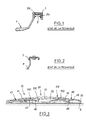
- This document describes a deflector having a profile P, provided with mounting means 1 on a brush frame 3, as can be seen in FIG. 1.
- the mounting means comprise clamps 1 suitable for snapping onto the frame 3, said clamps 1 having an inverted U section, so as to cover the frame 3 of similar shape and to be clipped onto the two wings 2a and 2b thereof.
- the present invention relates to an improved wiper device and deflector, in particular remedying the aforementioned drawbacks.
- the invention therefore provides a wiper device comprising an arm and a wiper blade, this device being able to be equipped with a deflector comprising a profile for deflecting air flows, capable of be removably mounted on an armature of the arm or of the wiper blade, the armature being in the form of a stirrup comprising two wings.
- the wiper device is characterized in that the deflector comprises a flange applied against a wing of the frame and thus held by means of a retaining element engaged in a cutout opening onto a free edge of said flange , said retaining element being integral with the frame.
- the edge of the deflector comprises abutment means capable of holding the retaining element engaged in said cutout, said abutment means being able to deform elastically in order to allow the element to be released. retained outside the cut.
- the retainer is a head rivet.
- the edge of the deflector extends longitudinally over the entire length of the profile, and has the general shape of an elongated flat plate comprising at its upper end a bent part, connected to the internal surface of the profile.
- the cut has the shape of a "U”, comprising an opening bordered by two rectilinear edges connected to a semi-circular bottom, capable of coming to bear with said retaining element.
- the stop means comprise at least one flexible tongue substantially coplanar with said flat plate and the free end of which extends beyond said flat plate to form a projecting shoulder adapted to come into abutment with a free edge of the frame.
- the flat plate comprises at its upper part elastic means capable of exerting a restoring torque tending to hold the shoulders of said flexible tongues in abutment against the free edge of the frame.
- These elastic means preferably comprise at least one tongue connected by an edge to the flat plate, at rest making an angle relative to the latter, capable of being folded elastically towards the flat plate by pressing on the wing.
- the invention also relates to a wiper deflector intended to equip an arm or a wiper blade to form a wiper device according to the invention.
- a wiper device comprising an arm and a wiper blade provided with a squeegee intended to be applied against a surface to be wiped, the blade being shown in the figure. 3.
- a wiper blade 10 intended to be equipped with a deflector according to the invention.
- This brush has a frame 20, of elongated shape and having a cross section in the shape of an inverted "U", comprising two lateral wings connected at right angles to a back 212. The wings terminate at their free end opposite to the back 212 by a free edge 215 plane, parallel to the back 212.
- the frame 20 is intended to be carried, in known manner, by a wiper arm not shown.
- the back 212 is generally perforated in a central region 22 of the frame 20, and the frame 20 has at this level a transverse pin 25 extending between the wings.
- This pin 25 is intended to be received in a housing provided at the end of the wiper arm, to ensure an articulated connection between the arm and the frame 20.
- the brush 10 further comprises a squeegee 30, generally made of elastomeric material, in contact with a surface to be wiped S.
- This squeegee 30 is carried by a system of spreaders 40, mounted on articulations 41, 42 provided at the ends of the frame 20.
- the spreader system 40 comprises an intermediate spreader 45 carrying, at each end, articulated, two secondary spreaders 46.
- the brush 10 is intended to support a deflector according to the invention. To do this, provision is made for retaining means 250 of the deflector on the frame 20, which will be described in detail below.
- FIGS. 4 and 4 A deflector 100 according to the invention, suitable for being mounted on a brush frame 20, equipped with retaining means 250.
- This deflector comprises a profile 110 of a type known in itself having an external surface suitable for deflecting the air flows in order to exert an aerodynamic force of plating the brush 10 on the surface to be wiped S.
- the profile 110 is elongated in the direction of a longitudinal axis and has a concave surface 111 facing the direction of incidence of the air flows, shown diagrammatically by the arrow in FIG. 5, substantially parallel to the plane of the surface to be wiped S.
- the profile 110 has a convex surface 112 facing the part to be wiped.
- the concave 111 and convex 112 surfaces are connected on a front edge 120, rounded, convex towards the outside.
- the surface 112 comprises a first zone 1110 extending from the front edge 120 towards the rear, that is to say towards the squeegee of the brush, not shown in FIG. 4.
- the first zone 1110 is extended towards the high relative to the first, that is to say away from the surface to be wiped, by a rounded region 1125 convex towards the outside, connecting to a second zone 1130, substantially planar and extending in one direction making an angle close to 90 ° with the part of the first zone 1110 adjacent to the front edge 120.
- the profile 110 is preferably made of a rigid material and will advantageously be provided at its front edge 120 with one or more rubber beads capable of being interposed between the profile and the surface to be wiped at high vehicle speeds.
- the length of the deflector is such that it shelters the scraper of the incident air flows as much as possible; advantageously, the length of the deflector is substantially equal to the length of the squeegee.
- FIGS. 4 and 5 The means used, in accordance with the invention, for mounting the deflector 100 on the frame 20 will be described with reference to FIGS. 4 and 5.
- the wings of the frame are referenced 210 and 211.
- the deflector 100 has a flange 140 intended to be applied by a face 1400 on the external face 2100 of the wing 210 of the frame.
- the rim 140 has the shape of a flat plate elongated in the direction of the axis X, of substantially rectangular section, connected at its upper end by a bent part 142 on the second zone 1130 of the profile 110, preferably at right angles. , so that the rim 140 extends parallel to the plane of the second zone 1130.
- the rim 140 according to the invention is provided with at least one cutout 150 opening onto its free edge 144, parallel to the axis X.
- the rim 140 comprises two cutouts 150, arranged symmetrically on either side of 'a middle zone of the deflector 100.
- Each cutout 150 preferably has the shape of a "U”, comprising two parallel edges 151, 152, which connect at right angles to the free edge 144 connected by a bottom 153 in the form of a semicircle, the concavity of which is facing the opening of the cutout 150.
- Each cutout 150 is intended to receive a retaining element 250 secured to the frame 20.
- This retaining element 250 can be the subject of various alternative embodiments.
- the retaining element 250 is a head rivet.
- This rivet 250 comprises a trunk of cylindrical section 251 extending along an axis Y, engaged at one end 252 in a bore 214 provided on the wing 210 and connected to the opposite end on an enlarged head 254.
- the rivet 250 and the arma ture 20 are metallic, and the rivet 250 is electro-welded to the frame 20.
- the axis Y of the trunk 251 extends perpendicular to the plane of the face 2100 of the wing 210.
- the enlarged head 254 comprises at its junction with the trunk 251 a base 253 perpendicular to the axis Y, therefore parallel to the plane of the face 2100.
- the cutout 150 and the retaining element 250 are adapted to cooperate with each other; for this purpose, the distance between the edges 151, 152 is substantially equal to the diameter of the trunk 251, while the diameter of the base 253 is significantly greater than this distance, so as to immobilize axially in the direction of the axis Y the deflector 100 with respect to the frame 20.
- the retaining element keeps the faces 1400 and 2100 pressed against each other.
- heads 254 can be used, but it should be noted that the distance between the base 253 of the head 254 and the face 2100 must correspond to the thickness of the rim 140 measured at the level of the cutout 150.
- the base 253 is supported on the face 1401 of the rim 140 opposite the bearing face 1400, and keeps the face 1400 of the rim 140 pressed against the side 2100 of wing 210.
- the cylindrical surface of the trunk 251 of the rivet 250 rests against the semi-circular free edge 153 of the cutout 150.
- abutment means are provided for holding the retaining element 250 in the cutout 150.
- These abutment means preferably consist of tongues 160 formed on the flange 140.
- each tongue 160 is bordered by two rectilinear recesses 161, 162 extending perpendicular to the axis X from the free edge 144 over part of the width of the rim 140.
- These recesses 161, 162 extend over a width such that they give the tongue 160 sufficient flexibility to flex out of the plane of the face 1400, as will be explained below.
- two tongues 160 are provided arranged on each side of a cutout 150.
- the tongues 160 have a face 1600coplanar with the face 1400 of the rim.
- the tongues 160 extend beyond the free edge 144 to form openings 165, projecting perpendicularly on the face 1600, away from the profile 110.
- the openings 165 form a shoulder 166 connecting at right angles to the face 1600 of the tongues, with a view to cooperating with the flat face of the free edge 215 of the wing 210.
- the thickness of a tongue 160 measured perpendicular to a face 1600 is preferably less than the thickness of the flange 140, in order to give more flexibility to the tongue.
- the thickness of a tongue 160 and the length of the rectilinear recesses 161, 162 is chosen as a function of the nature of the material constituting the deflector, and of the required mechanical characteristics.
- the flange 140 further comprises elastic means 180 bearing on the upper part of the face 2100, close to the back 212, in order to exert a torque tending to press the flange of the adjacent tongues at the shoulder 166 against the free edge 215 of the wing 210.
- the elastic means 180 are advantageously formed by flexible tongues 180 extending out of the plane of the face 1400 of the rim 140.
- Each flexible tongue 180 forms an angle with the plane of the face 1400 between 10 and 50 °, and is connected to its base on an edge of a window 181 opening onto the upper part of the rim 140. In the bent position, the tongues 180 are liable to fold down in the plane of the face 1400.
- each flexible tongue 180 is arranged in the extension of a tongue 160, in a direction perpendicular to the axis X.
- FIGS. 6A to 6C The different stages of mounting the deflector 100 on the frame 20 are illustrated in FIGS. 6A to 6C.
- the deflector is positioned axially with respect to the frame in order to place opposite the openings of the cutouts 150 and the trunks of the rivets 250.
- the face 1400 of the rim 140 is applied against the face 2100 of the wing 210.
- the openings 165 are supported on the face 2100 and the tongues 160 flex in the direction of the profile 110.
- the rim 140 is inserted in the direction of the arrow F in FIG. 6B between the base 253 of the head 254 of the rivet 250 and the face 2100.
- the cylindrical surface of the trunk 252 of the rivet 250 comes to bear on the semi-circular free edge 153 of the cutout 150, while the shoulders 166 of the tongues reach the free edge 215.
- the tongues 160 resume their rest position, faces 1400 and 1600 coplanar.
- the shoulders 166 abut against the edge 215, in accordance with FIG. 6C, and block the retaining element 250 in the cutout 150.
- the flexible tongues 180 have folded down in the plane of the face 1400 and exert a restoring torque in the counterclockwise direction of FIGS. 6A to 6C tending to keep the edge d pressed against each other.
- a wiper blade fitted with a deflector according to the invention proves to be particularly advantageous, in particular because it allows easy dismantling of the deflector, without risk of damage to the latter.
- the rim 140 can be attached to the profile 110 or come from formation by molding. In all cases, the structure of the deflector is simple and inexpensive to produce.
Applications Claiming Priority (2)
| Application Number | Priority Date | Filing Date | Title |
|---|---|---|---|
| FR9204295A FR2689837B1 (fr) | 1992-04-08 | 1992-04-08 | Dispositif d'essuie-glace incorporant un deflecteur. |
| FR9204295 | 1992-04-08 |
Publications (2)
| Publication Number | Publication Date |
|---|---|
| EP0565443A1 true EP0565443A1 (de) | 1993-10-13 |
| EP0565443B1 EP0565443B1 (de) | 1996-06-12 |
Family
ID=9428631
Family Applications (1)
| Application Number | Title | Priority Date | Filing Date |
|---|---|---|---|
| EP93400910A Expired - Lifetime EP0565443B1 (de) | 1992-04-08 | 1993-04-07 | Scheibenwischanlage mit Windableiter |
Country Status (3)
| Country | Link |
|---|---|
| EP (1) | EP0565443B1 (de) |
| DE (1) | DE69303107T2 (de) |
| FR (1) | FR2689837B1 (de) |
Cited By (10)
| Publication number | Priority date | Publication date | Assignee | Title |
|---|---|---|---|---|
| EP0599637A1 (de) * | 1992-11-25 | 1994-06-01 | Trico Limited | Windleitfläche für Scheibenwischer |
| EP0664247A1 (de) * | 1994-01-25 | 1995-07-26 | Valeo Systemes D'essuyage | Kraftfahrzeugscheibenwischer mit aerodynamischem Windabweiser |
| EP0684171A1 (de) * | 1994-05-26 | 1995-11-29 | Valeo Systemes D'essuyage | Mit einer Scheibenwaschschiene versehener Scheibenwischer für Kraftfahrzeuge |
| EP0723899A1 (de) * | 1995-01-24 | 1996-07-31 | Cooper Industries, Inc. | Scheibenwischer |
| FR2743039A1 (fr) * | 1995-12-27 | 1997-07-04 | Valeo Systemes Dessuyage | Deflecteur pour essuie-glace de vehicule automobile muni de moyens perfectionnes d'accrochage et essuie-glace muni d'un tel deflecteur |
| EP0783999A1 (de) * | 1996-01-15 | 1997-07-16 | Société Noiséenne Outillage de Presse S.N.O.P. SA | Herstellungsverfahren für Scheibenwischer mit Windableiter |
| US5722107A (en) * | 1995-01-19 | 1998-03-03 | Valeo Systemes D'essuyage | Motor vehicle windscreen wiper comprising an improved spray line |
| GB2332853A (en) * | 1997-12-31 | 1999-07-07 | Acdtridon Europ Ltd | Wiper with aerofoil assembly |
| US6067687A (en) * | 1998-07-06 | 2000-05-30 | Lain Chuan Rubber Co., Ltd. | Windshield wiper blade assembly |
| US20120066857A1 (en) * | 2010-09-22 | 2012-03-22 | Webert Christopher A | Beam blade windshield wiper assembly having a fluid manifold mounting system |
Citations (4)
| Publication number | Priority date | Publication date | Assignee | Title |
|---|---|---|---|---|
| US3685086A (en) * | 1969-09-29 | 1972-08-22 | Karl Frohlich | Pressure intensifier for windshield wipers |
| EP0234286A1 (de) * | 1986-01-24 | 1987-09-02 | Paul Journee S.A. | Wischarm für Scheibenwischer |
| EP0410854A1 (de) * | 1989-07-26 | 1991-01-30 | Valeo Systemes D'essuyage | Beweglicher Luftableiter für Scheibenwischerblatt, insbesondere für Kraftfahrzeug |
| WO1991018772A1 (de) * | 1990-05-26 | 1991-12-12 | Robert Bosch Gmbh | Wischblatt für scheiben von kraftfahrzeugen |
-
1992
- 1992-04-08 FR FR9204295A patent/FR2689837B1/fr not_active Expired - Fee Related
-
1993
- 1993-04-07 EP EP93400910A patent/EP0565443B1/de not_active Expired - Lifetime
- 1993-04-07 DE DE69303107T patent/DE69303107T2/de not_active Expired - Fee Related
Patent Citations (4)
| Publication number | Priority date | Publication date | Assignee | Title |
|---|---|---|---|---|
| US3685086A (en) * | 1969-09-29 | 1972-08-22 | Karl Frohlich | Pressure intensifier for windshield wipers |
| EP0234286A1 (de) * | 1986-01-24 | 1987-09-02 | Paul Journee S.A. | Wischarm für Scheibenwischer |
| EP0410854A1 (de) * | 1989-07-26 | 1991-01-30 | Valeo Systemes D'essuyage | Beweglicher Luftableiter für Scheibenwischerblatt, insbesondere für Kraftfahrzeug |
| WO1991018772A1 (de) * | 1990-05-26 | 1991-12-12 | Robert Bosch Gmbh | Wischblatt für scheiben von kraftfahrzeugen |
Cited By (16)
| Publication number | Priority date | Publication date | Assignee | Title |
|---|---|---|---|---|
| EP0599637A1 (de) * | 1992-11-25 | 1994-06-01 | Trico Limited | Windleitfläche für Scheibenwischer |
| EP0664247A1 (de) * | 1994-01-25 | 1995-07-26 | Valeo Systemes D'essuyage | Kraftfahrzeugscheibenwischer mit aerodynamischem Windabweiser |
| FR2715367A1 (fr) * | 1994-01-25 | 1995-07-28 | Valeo Systemes Dessuyage | Essuie-glace pour véhicule automobile équipé d'un déflecteur aérodynamique. |
| EP0684171A1 (de) * | 1994-05-26 | 1995-11-29 | Valeo Systemes D'essuyage | Mit einer Scheibenwaschschiene versehener Scheibenwischer für Kraftfahrzeuge |
| FR2720355A1 (fr) * | 1994-05-26 | 1995-12-01 | Valeo Systemes Dessuyage | Essuie-glace pour véhicule automobile équipé d'une rampe de lave-glace. |
| US5722107A (en) * | 1995-01-19 | 1998-03-03 | Valeo Systemes D'essuyage | Motor vehicle windscreen wiper comprising an improved spray line |
| EP0723899A1 (de) * | 1995-01-24 | 1996-07-31 | Cooper Industries, Inc. | Scheibenwischer |
| FR2743039A1 (fr) * | 1995-12-27 | 1997-07-04 | Valeo Systemes Dessuyage | Deflecteur pour essuie-glace de vehicule automobile muni de moyens perfectionnes d'accrochage et essuie-glace muni d'un tel deflecteur |
| FR2743536A1 (fr) * | 1996-01-15 | 1997-07-18 | Noiseenne Outillage De Presse | Procede pour la fabrication de balais d'essuie-glaces a deflecteur |
| EP0783999A1 (de) * | 1996-01-15 | 1997-07-16 | Société Noiséenne Outillage de Presse S.N.O.P. SA | Herstellungsverfahren für Scheibenwischer mit Windableiter |
| GB2332853A (en) * | 1997-12-31 | 1999-07-07 | Acdtridon Europ Ltd | Wiper with aerofoil assembly |
| GB2332853B (en) * | 1997-12-31 | 2001-09-12 | Acdtridon Europ Ltd | Wiper blade and aerofoil assembly |
| US6067687A (en) * | 1998-07-06 | 2000-05-30 | Lain Chuan Rubber Co., Ltd. | Windshield wiper blade assembly |
| US20120066857A1 (en) * | 2010-09-22 | 2012-03-22 | Webert Christopher A | Beam blade windshield wiper assembly having a fluid manifold mounting system |
| US9045114B2 (en) * | 2010-09-22 | 2015-06-02 | Trico Products Corporation | Beam blade windshield wiper assembly having a fluid manifold mounting system |
| GB2498277B (en) * | 2010-09-22 | 2016-08-31 | Trico Products Corp | Beam blade windshield wiper assembly having a fluid manifold mounting system |
Also Published As
| Publication number | Publication date |
|---|---|
| FR2689837A1 (fr) | 1993-10-15 |
| DE69303107D1 (de) | 1996-07-18 |
| FR2689837B1 (fr) | 1994-07-08 |
| DE69303107T2 (de) | 1996-12-12 |
| EP0565443B1 (de) | 1996-06-12 |
Similar Documents
| Publication | Publication Date | Title |
|---|---|---|
| EP1937524B1 (de) | Verbinder zum montieren und verbinden eines wischblattes mit einem antriebsarmende | |
| EP0410854B1 (de) | Beweglicher Luftableiter für Scheibenwischerblatt, insbesondere für Kraftfahrzeug | |
| EP1098797B1 (de) | Kraftfahrzeugscheibenwischer mit schwenkbarem riegel | |
| EP0429334B1 (de) | Scheibenwischer mit Windableiter, insbesondere für Kraftfahrzeug | |
| EP0455520B1 (de) | Verbindungsstück zum Verbinden eines Scheibenwischerblattes mit einem Scheibenwischerarm | |
| FR2629030A1 (fr) | Porte-balais d'essuie-glace comportant un verrou | |
| FR3048935A1 (fr) | Dispositif d'essuie-glace comportant un adaptateur de bras d'essuie-glace | |
| EP0565443B1 (de) | Scheibenwischanlage mit Windableiter | |
| EP3251905B1 (de) | Anschlussadapter des freien endabschnitts eines scheibenwischerarms, und anordnung, die einen solchen adapter und einen scheibenwischerarm umfasst | |
| WO1999055994A1 (fr) | Dispositif de support d'une vitre sur un leve-vitre de porte de vehicule | |
| EP0565437B1 (de) | Windableiter für Scheibenwischvorrichtung mit abnehmbarer weicher Kante | |
| WO1984000523A1 (fr) | Balai d'essuie-glace | |
| FR2696393A1 (fr) | Essuie-glace de véhicule automobile, tête d'entraînement pour un tel essuie-glace, et coiffe de protection de la tête d'entraînement. | |
| EP0433169B1 (de) | Luftleitvorrichtung für Scheibenwischerblatt | |
| EP0329515A1 (de) | Verbindungsstück, um einen Scheibenwischerblattbügel und einen Arm mit U-förmig gekrümmtem Ende zu verbinden | |
| WO2022017806A1 (fr) | Dispositif de connexion d'un balai d'essuyage à un bras d'essuie-glace | |
| EP0623496B1 (de) | Scheibenwischer mit einem Montagekeil | |
| EP3248848B1 (de) | Befestigungsvorrichtung für die montage eines scheibenwischerblatts auf einem scheibenwischerarm, und entsprechendes scheibenwischsystem | |
| EP0567389B1 (de) | Wischarm mit wenigstens einer Anpressdruckfeder | |
| FR2534206A1 (fr) | Essuie-glace comportant une fixation simplifiee du bras par rapport a sa chape d'entrainement | |
| FR2730687A1 (fr) | Balai d'essuie-glace comportant une coiffe d'arret de la raclette d'essuyage montee sur une griffe de maintien de la raclette | |
| FR3063950A1 (fr) | Capot, dispositif de connexion pour le montage d’un balai d’essuie-glace sur un bras d’essuie-glace et systeme d’essuyage correspondants | |
| FR2703643A1 (fr) | Essuie-glace de véhicule automobile comportant une cale de montage. | |
| WO2007071671A1 (fr) | Agencement d'un bras d'essuie-glace de vehicule automobile sur une tete d'entrainement | |
| FR2761321A1 (fr) | Essuie-glace de vehicule automobile comportant une cale de rattrapage de jeu |
Legal Events
| Date | Code | Title | Description |
|---|---|---|---|
| PUAI | Public reference made under article 153(3) epc to a published international application that has entered the european phase |
Free format text: ORIGINAL CODE: 0009012 |
|
| AK | Designated contracting states |
Kind code of ref document: A1 Designated state(s): DE ES GB IT |
|
| 17P | Request for examination filed |
Effective date: 19940221 |
|
| 17Q | First examination report despatched |
Effective date: 19941229 |
|
| GRAH | Despatch of communication of intention to grant a patent |
Free format text: ORIGINAL CODE: EPIDOS IGRA |
|
| RAP1 | Party data changed (applicant data changed or rights of an application transferred) |
Owner name: VALEO SYSTEMES D'ESSUYAGE |
|
| GRAA | (expected) grant |
Free format text: ORIGINAL CODE: 0009210 |
|
| AK | Designated contracting states |
Kind code of ref document: B1 Designated state(s): DE ES GB IT |
|
| PG25 | Lapsed in a contracting state [announced via postgrant information from national office to epo] |
Ref country code: IT Free format text: LAPSE BECAUSE OF FAILURE TO SUBMIT A TRANSLATION OF THE DESCRIPTION OR TO PAY THE FEE WITHIN THE PRE;WARNING: LAPSES OF ITALIAN PATENTS WITH EFFECTIVE DATE BEFORE 2007 MAY HAVE OCCURRED AT ANY TIME BEFORE 2007. THE CORRECT EFFECTIVE DATE MAY BE DIFFERENT FROM THE ONE RECORDED.SCRIBED TIME-LIMIT Effective date: 19960612 Ref country code: ES Free format text: THE PATENT HAS BEEN ANNULLED BY A DECISION OF A NATIONAL AUTHORITY Effective date: 19960612 |
|
| REF | Corresponds to: |
Ref document number: 69303107 Country of ref document: DE Date of ref document: 19960718 |
|
| GBT | Gb: translation of ep patent filed (gb section 77(6)(a)/1977) |
Effective date: 19960801 |
|
| PLBE | No opposition filed within time limit |
Free format text: ORIGINAL CODE: 0009261 |
|
| STAA | Information on the status of an ep patent application or granted ep patent |
Free format text: STATUS: NO OPPOSITION FILED WITHIN TIME LIMIT |
|
| 26N | No opposition filed | ||
| REG | Reference to a national code |
Ref country code: GB Ref legal event code: IF02 |
|
| PGFP | Annual fee paid to national office [announced via postgrant information from national office to epo] |
Ref country code: GB Payment date: 20020402 Year of fee payment: 10 |
|
| PGFP | Annual fee paid to national office [announced via postgrant information from national office to epo] |
Ref country code: DE Payment date: 20020410 Year of fee payment: 10 |
|
| PG25 | Lapsed in a contracting state [announced via postgrant information from national office to epo] |
Ref country code: GB Free format text: LAPSE BECAUSE OF NON-PAYMENT OF DUE FEES Effective date: 20030407 |
|
| PG25 | Lapsed in a contracting state [announced via postgrant information from national office to epo] |
Ref country code: DE Free format text: LAPSE BECAUSE OF NON-PAYMENT OF DUE FEES Effective date: 20031101 |
|
| GBPC | Gb: european patent ceased through non-payment of renewal fee |
Effective date: 20030407 |