EP3248848B1 - Befestigungsvorrichtung für die montage eines scheibenwischerblatts auf einem scheibenwischerarm, und entsprechendes scheibenwischsystem - Google Patents
Befestigungsvorrichtung für die montage eines scheibenwischerblatts auf einem scheibenwischerarm, und entsprechendes scheibenwischsystem Download PDFInfo
- Publication number
- EP3248848B1 EP3248848B1 EP17170969.4A EP17170969A EP3248848B1 EP 3248848 B1 EP3248848 B1 EP 3248848B1 EP 17170969 A EP17170969 A EP 17170969A EP 3248848 B1 EP3248848 B1 EP 3248848B1
- Authority
- EP
- European Patent Office
- Prior art keywords
- connector
- cover
- securing device
- sliding
- locking
- Prior art date
- Legal status (The legal status is an assumption and is not a legal conclusion. Google has not performed a legal analysis and makes no representation as to the accuracy of the status listed.)
- Active
Links
Images


Classifications
-
- B—PERFORMING OPERATIONS; TRANSPORTING
- B60—VEHICLES IN GENERAL
- B60S—SERVICING, CLEANING, REPAIRING, SUPPORTING, LIFTING, OR MANOEUVRING OF VEHICLES, NOT OTHERWISE PROVIDED FOR
- B60S1/00—Cleaning of vehicles
- B60S1/02—Cleaning windscreens, windows or optical devices
- B60S1/04—Wipers or the like, e.g. scrapers
- B60S1/32—Wipers or the like, e.g. scrapers characterised by constructional features of wiper blade arms or blades
- B60S1/40—Connections between blades and arms
- B60S1/4038—Connections between blades and arms for arms provided with a channel-shaped end
- B60S1/4045—Connections between blades and arms for arms provided with a channel-shaped end comprising a detachable intermediate element mounted on the channel-shaped end
-
- B—PERFORMING OPERATIONS; TRANSPORTING
- B60—VEHICLES IN GENERAL
- B60S—SERVICING, CLEANING, REPAIRING, SUPPORTING, LIFTING, OR MANOEUVRING OF VEHICLES, NOT OTHERWISE PROVIDED FOR
- B60S1/00—Cleaning of vehicles
- B60S1/02—Cleaning windscreens, windows or optical devices
- B60S1/04—Wipers or the like, e.g. scrapers
- B60S1/32—Wipers or the like, e.g. scrapers characterised by constructional features of wiper blade arms or blades
- B60S1/38—Wiper blades
- B60S1/3848—Flat-type wiper blade, i.e. without harness
- B60S1/3849—Connectors therefor; Connection to wiper arm; Attached to blade
-
- B—PERFORMING OPERATIONS; TRANSPORTING
- B60—VEHICLES IN GENERAL
- B60S—SERVICING, CLEANING, REPAIRING, SUPPORTING, LIFTING, OR MANOEUVRING OF VEHICLES, NOT OTHERWISE PROVIDED FOR
- B60S1/00—Cleaning of vehicles
- B60S1/02—Cleaning windscreens, windows or optical devices
- B60S1/04—Wipers or the like, e.g. scrapers
- B60S1/32—Wipers or the like, e.g. scrapers characterised by constructional features of wiper blade arms or blades
- B60S1/38—Wiper blades
- B60S1/3848—Flat-type wiper blade, i.e. without harness
- B60S1/3849—Connectors therefor; Connection to wiper arm; Attached to blade
- B60S1/3851—Mounting of connector to blade assembly
- B60S1/3856—Gripping the blade
-
- B—PERFORMING OPERATIONS; TRANSPORTING
- B60—VEHICLES IN GENERAL
- B60S—SERVICING, CLEANING, REPAIRING, SUPPORTING, LIFTING, OR MANOEUVRING OF VEHICLES, NOT OTHERWISE PROVIDED FOR
- B60S1/00—Cleaning of vehicles
- B60S1/02—Cleaning windscreens, windows or optical devices
- B60S1/04—Wipers or the like, e.g. scrapers
- B60S1/32—Wipers or the like, e.g. scrapers characterised by constructional features of wiper blade arms or blades
- B60S1/40—Connections between blades and arms
- B60S1/4038—Connections between blades and arms for arms provided with a channel-shaped end
- B60S1/4041—Connections between blades and arms for arms provided with a channel-shaped end the channel-shaped end comprising a pivot pin mounted between the side walls
-
- B—PERFORMING OPERATIONS; TRANSPORTING
- B60—VEHICLES IN GENERAL
- B60S—SERVICING, CLEANING, REPAIRING, SUPPORTING, LIFTING, OR MANOEUVRING OF VEHICLES, NOT OTHERWISE PROVIDED FOR
- B60S1/00—Cleaning of vehicles
- B60S1/02—Cleaning windscreens, windows or optical devices
- B60S1/04—Wipers or the like, e.g. scrapers
- B60S1/32—Wipers or the like, e.g. scrapers characterised by constructional features of wiper blade arms or blades
- B60S1/38—Wiper blades
- B60S2001/3812—Means of supporting or holding the squeegee or blade rubber
- B60S2001/3822—Means of supporting or holding the squeegee or blade rubber characterised by additional means to prevent longitudinal sliding of squeegee in support, e.g. clips
-
- B—PERFORMING OPERATIONS; TRANSPORTING
- B60—VEHICLES IN GENERAL
- B60S—SERVICING, CLEANING, REPAIRING, SUPPORTING, LIFTING, OR MANOEUVRING OF VEHICLES, NOT OTHERWISE PROVIDED FOR
- B60S1/00—Cleaning of vehicles
- B60S1/02—Cleaning windscreens, windows or optical devices
- B60S1/04—Wipers or the like, e.g. scrapers
- B60S1/32—Wipers or the like, e.g. scrapers characterised by constructional features of wiper blade arms or blades
- B60S1/40—Connections between blades and arms
- B60S1/4038—Connections between blades and arms for arms provided with a channel-shaped end
- B60S2001/4058—Connections between blades and arms for arms provided with a channel-shaped end comprising a separate locking element, e.g. in addition to an intermediate element
Definitions
- the present invention relates to a fastening device for assembling a wiper blade to a driving arm of a motor vehicle.
- the invention also relates to a wiper system comprising a wiper blade, a drive arm and such a fixing device.
- the fasteners allow the connection of wiper blades to appropriate drive arms.
- the fasteners comprise, on the one hand, a connector assembled to the wiper blade and the drive arm, and on the other hand, a cover intended to be assembled and locked on the connector.
- the fixing device comprises means for connecting the drive arm to the connector mounted on the wiper blade, either directly or indirectly via an adapter, and assembly means and locking the cover on the connector.
- arms known from the state of the art such as hook arms, lateral pivot axis arms, longitudinal clipping arms, and the like.
- fasteners depending on the style of the arm and directions to the right or left of the vehicle.
- document is known DE10122764 a windscreen wiper blade equipped with a metal connector crimped on metal stiffening vertebrae of the blade and on which a hood, comprising a metal blade, locks the driving arm, in particular by preventing the vertical withdrawal of the adapter received in the connector.
- this metal connection can cause difficulties in assembly and disassembly.
- oxidation may appear on the various parts causing a difficulty of locking the wiper blade to the drive arm through the cover and the connector, so that the wiper blade can be lost in operation.
- the document DE 101 22 764 discloses a fixing device for mounting a windscreen wiper blade of a motor vehicle wiper system on a drive arm according to the prior art.
- One of the aims of the present invention is to at least partially overcome these problems of the state of the art by proposing a cheaper alternative facilitating the mounting and disassembling the attachment device on the wiper blade to connect and lock the drive arm to the wiper blade, which can be standardized.
- the cover, the connector and the first and second sliding and locking means they carry respectively can be made simply and cheaply.
- the separate location for the one or more sliding means and the locking means or means, at least on the hood side makes the locking more reliable.
- the fastening device thus allows assembly and disassembly of the wiper blade on the improved arm.
- the invention also relates to a motor vehicle wiper system comprising at least one wiper blade, at least one drive arm of the wiper blade, and a fixing device as described above. , fixing the wiper blade to the drive arm.
- the wiper system 1 comprises at least one windscreen wiper blade 3, at least one drive arm 5 and a fastening device 7 for assembling the windscreen wiper blade 3 to the driving arm 5.
- the wiper blade 3 extends longitudinally in a direction L.
- the longitudinal, vertical and transverse directions indicated on the drawing will be adopted without limitation.
- the terms upper / lower, above / below are designated with reference to the arrangement of the elements in the figures in the vertical direction V.
- the wiper blade 3 comprises a deflector 9 substantially shaped fin (or spoiler in English) and a wiper blade 11.
- the deflector 9 and the wiper blade 11 are of flexible material. They can be obtained by molding or extrusion of one or more materials.
- the wiper blade 3 generally comprises at least one stiffening vertebra (called "spline" in English) not visible in the figures.
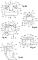
- the deflector 9 may have a housing 13 visible on the figure 2 , for example here a cut form of the deflector 9, to receive an element of the fastening device 7.
- the fixing device 7 allows the assembly and articulation of the wiper blade 3 on the free end of the drive arm 5. It comprises for this purpose a connector 15a or 15b and a cover 17.
- a fixing device 7 which can comprise two types of connectors 15a and 15b whose differences will be explained later.
- the connector 15a or 15b serves as an interface with the wiper blade 3 and the drive arm 5, while the cover 17 allows the locking of the assembly.
- the connector 15a or 15b thus cooperates with the cover 17 to hold and fix the wiper blade 3 on the drive arm 5.
- the fixing device 7 comprises one or more first sliding means 19 carried by the connector 15a or 15b and one or more second sliding means 21 carried by the cover 17 and complementary to the first sliding means 19, so as to allow the assembly of the connector 15a or 15b and the cover 17.
- the first and second sliding means 19, 21 complementary comprise at least one tongue 211 and at least one groove 191 associated in which the tongue 211 is configured to slide, as will be described later.
- the cover 17 and the connector 15a or 15b are configured to slide relative to one another along a sliding axis A ( figure 1 ).
- the sliding is done by longitudinal translation, substantially parallel to the longitudinal direction L.
- the first and second sliding means 19, 21 complementary are advantageously shaped so as to prevent tearing of the cover 17 and / or the connector 15a or 15b in a direction perpendicular to the sliding axis A, here in the vertical direction V.
- the fixing device 7 comprises one or more first locking means 23 carried by the connector 15a or 15b, and one or more second locking means 25 carried by the cover 17 and complementary to the first locking means 23, for locking the cover 17 and the connector 15a or 15b in a final assembled position, as is better visible on the Figures 3a to 3c .
- the first and second locking means 23, 25 are configured to block the longitudinal movement of the connector 15a or 15b relative to the cover 17.
- the first and second locking means 23, 25 described in more detail below may be means by form cooperation.
- it is a locking means 23, 25 for reversibly locking the cover 17 and the connector 15a or 15b.
- the first and second complementary locking means 23, 25 comprise at least one hook 251 ( figure 3c ) and at least one opening 231 ( Figures 3a, 3b ) associated in which the hook 251 is configured to engage.
- the cover 17 and the second sliding means 21 and locking 25 carried by the cover 17 are preferably made in one piece. On the side of the cover 17, the second sliding means 21 are distinct from the second locking means 25.
- the connector 15a or 15b and the first sliding means 19 and locking 23 carried by the connector 15a or 15b are preferably made of a single piece.
- the first sliding means 19 are also distinct from the first locking means 23.
- the fixing device 7 advantageously allows the connector 15a or 15b to be assembled to the cover 17 in a so-called delivery position, also called an open position or a pre-assembled position, visible on the figure 3d .
- the cover 17 and the connector 15a or 15b are assembled to each other without cooperation of the first and second locking means 23, 25.
- This delivery position allows the fixing device 7 to be mounted on the wiper blade 3 and the driving arm 5 before fixing and locking by cooperation of the first and second locking means 23, 25.
- the fixing device 7 comprises at least a first holding means 27 ( figure 2 ) carried by the connector 15a or 15b and at least one second holding means 29 ( figure 3b ) carried by the cover 17 and complementary to a respective first holding 27.
- first (s) and second (s) holding means 27, 29 are configured to hold the cover 17 and the connector 15a or 15b in the delivery position.
- the first (s) and second (s) holding means 27, 29 comprise at least one stop 271 ( figure 2 ) and at least one plate 291 ( figure 3b ) associated and shaped so as to bear against the stop 271 in the delivery position ( figure 3d ).
- first holding means 27 provided on the connector 15a or 15b can also be made in one piece with the latter.
- second retaining means 29 provided on the cover 17 can be made in one piece with the latter.
- the connector 15a or 15b configured to be connected to the cover 17 but also to the windscreen wiper blade 3 and to the drive arm 5 is described in more detail.
- the connector 15a or 15b has a longitudinal main extension shape, in other words, it extends in the longitudinal direction L.
- the connector 15a or 15b has a lower face 150 configured to be connected to the wiper blade 3 and an opposite upper face 151 configured to cooperate with the cover 17.
- the lower faces 150 and upper 151 are connected. by two opposite end faces 152 and 153, and two opposite lateral faces 154 and 155.
- the end faces 152 and 153 extend here in a plane parallel to the plane V, T and the opposite lateral faces 154 and 155 s extend here according to a plane parallel to the plane L, V.
- the first sliding means 19 are carried by the upper face 151 of the connector 15a or 15b.
- the first locking means 23 are carried by the opposite side faces 154 and 155 of the connector 15a or 15b.
- the connector 15a or 15b is mounted at the housing 13 on the deflector 9 of the wiper blade 3.
- the lower face 150 of the connector 15a or 15b has a retaining channel 30 of the wiper blade 11.
- the fixing device 7 may comprise an axis 31, in this example a transverse axis, mounted in the connector 15a or 15b and held by the cover 17 in the assembled state.
- the transverse axis 31 In the assembled state, the transverse axis 31 extends in the transverse direction T, perpendicular to the longitudinal direction L.
- This transverse axis 31 is configured to be connected, directly or via an adapter 33 to the arm training 5.
- the connector 15a or 15b may comprise for this purpose a housing 34 for receiving the adapter 33.
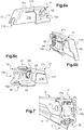
- Figures 6a to 6c illustrate the adapter 33 once mounted in the connector 15a according to a first embodiment described in more detail later and the figure 7 illustrates this connector 15a fixed on the end of the drive arm 5.
- the adapter 33 is mounted in the same way in the connector 15b according to a second embodiment described below.
- Means or fasteners, such as washers 35 can be provided for fixing the transverse axis 31 on the adapter 33.
- the housing 34 has a shape complementary to the shape of the adapter 33.
- this housing 34 is for example defined by two side walls 340, 341 interconnected at their lower ends by a bottom wall 342, on the opposite side to the upper face 151.
- the walls 340, 341, 342 are for example substantially flat.
- the side walls 340, 341 are, in the examples illustrated, inclined with respect to the plane defined by the bottom wall 342. In this example, the side walls 340, 341 are not parallel and converge towards the bottom wall 342, so that the housing 34 has a section substantially shaped "U" flared or isosceles trapezoidal shape of which one of the bases has been removed.
- the housing 34 is for example formed substantially in the center of the connector 15a or 15b in the longitudinal direction L, opening on both sides of the side faces 154 and 155.
- the wall of bottom 342 of the housing 34 faces an opening made on the upper face 151 of the connector 15a separating the upper face 151 into two parts.
- the connector 15a is symmetrical with respect to a plane P, called the median plane, extending in the transverse directions T and vertical V and passing through the center of the connector 15a (see figure 4a ).
- the symmetrical connector 15a can be assembled in any direction on the wiper blade 3.
- the first sliding means 19 are arranged on an upper part of the connector 15a intended to cooperate with the cover 17. More precisely, here the first sliding means 19 of the connector 15a are formed on an upper part of each lateral face 154, 155 of the connector 15a.
- the connector 15a comprises at least two grooves 191 per side face 154, 155 respectively associated and complementary to a tab 211 of the cover 17, so that the assembly of the cover 17 to the connector 15a, the tabs 211 of the cover 17 slide by longitudinal translation in the grooves 191 of the connector 15a.
- the first sliding means 19 are arranged symmetrically with respect to the plane P. As a result, the first sliding means 19 are provided on the side faces 154, 155 on either side of the housing 34.
- four distinct grooves 191 are formed on the upper parts of the side faces 154 and 155, two grooves being disposed on each side face 154, 155.
- the connector 15a has shapes 192 delimiting respectively a groove 191. These shapes 192 are called counterforms in relation to their complementarity of shapes with respect to the tabs 211 of the cover 17 detailed below. These counterforms 192 are substantially “L”, more precisely “L” inverted with respect to the vertical direction V on the Figures 4a to 4c .
- the connector 15a has as many counterforms 192 as grooves 191. According to the first embodiment, the connector 15a has four counterforms 192, two counterforms 192 being disposed on each lateral face 154, 155, in "L". Inverted on the upper part of the lateral faces 154 and 155 and which are symmetrical with respect to the plane P.
- the complementarity of shapes between the counterforms 192 and the tongues 211 of the cover 17 makes it possible to limit the relative displacement, here vertical, between the connector 15a and the cover 17.
- first locking means 23 of the connector 15a can also be made on each lateral face 154, 155 of the connector 15a.
- the first locking means 23 may be arranged on an upper part of the lateral faces 154, 155 below the first sliding means 19.
- the first sliding means 19 and the first locking means 23 are in this example provided in separate locations. of the connector 15a while being made in one piece with the connector 15a.
- the connector 15a has at least two openings 231 respectively associated and complementary to a hook 251 of the cover 17, so that when the cover 17 is connected to the connector 15a, the hooks 251 are configured to engage respectively openings 231 to block the longitudinal movement of the connector relative to the hood.
- the openings 231 are arranged on the lateral faces 154, 155 of the connector 15a.
- the first locking means 23 are arranged symmetrically with respect to the plane P. It follows that the first locking means 23 are provided on the side faces 154, 155 on either side of the housing 34.
- the first embodiment illustrated four openings 231 are formed on the upper part of the side faces 154 and 155, two openings 231 per side face 154 and 155.
- Each opening 231 is formed below a groove 191.
- the openings 231 may be of rectangular section.
- the first holding means 27 of the connector 15a may comprise at least one stop 271 (better visible on the figure 4e ) arranged at the junction between the upper face 151 and each end face 152, 153 of the connector 15a.
- the connector 15a therefore comprises at least two stops 271 arranged symmetrically with respect to the plane P.
- each stop 271 is arranged substantially centrally in the transverse direction T.
- each abutment 271 is arranged between two counterforms 192 substantially in "L" inverted delimiting respectively a groove 191 (see Figures 4b, 4c and 4e ).
- the connector 15b is asymmetrical with respect to the plane P, said median plane, extending in the transverse directions T and vertical V, and passing through the center of the connector 15b (see figure 5a ).
- This asymmetric connector 15b makes it possible to optimize the consumption of material.
- the asymmetrical connector 15b can be assigned to either a left or right direction.
- the first sliding means 19 of the connector 15b according to the second embodiment are not arranged symmetrically on the lateral faces 154, 155 on either side of the housing 34.
- Grooves 191, 191 ' can be arranged on the upper part of the lateral faces 154 and 155, but these grooves 191, 191 'are of different lengths on either side of the housing 34.
- the grooves 191 are longer on a first side to the left of housing 34 with reference to the orientation of the elements on the figure 5a , and the grooves 191 'are shorter on the other side of the housing 34, on the right with reference to the orientation on the figure 5a .
- the first locking means 23 are no longer arranged symmetrically with respect to the plane P.
- the first locking means 23 may be provided on each lateral face 154, 155 but only on one side, to the left with reference to the orientation of the figure 5a relative to the housing 34.
- the first locking means 23 comprise two openings 231 each being formed on a respective lateral face 154 or 155 of the connector 15b, on one side only with respect to the housing 34.
- the openings 231 are respectively arranged in below a groove 191 longer.
- the first holding means 27 is for example made by at least one stop 271 provided on one side of the connector 15b.
- the or each abutment 271 is for example arranged at the junction between the upper face 151 and only one end face 152 or 153, here the end face 152 which is on the side where the first sliding means 19 and the first locking means 23 are provided.
- the cover 17 is made of a plastic material.
- the cover 17 is intended to be fixed on the connector 15a or 15b on the opposite side to the assembled side on the wiper blade 11 having in particular the housing 30.
- the cover 17 has a longitudinal main extension shape, and therefore extends in the longitudinal direction L.
- the cover 17 has for example an open form with an upper wall 171 connecting an opposite front wall 172 and a rear wall 173, and two opposite side walls 174, 175.
- the front walls 172 and 173 rear here extend in a plane parallel to the plane V
- T and the side walls 174, 175 here extend in a plane parallel to the plane L, V.
- no wall is arranged facing the upper wall 171, conferring the "open form", that is to say that is not closed on all sides.
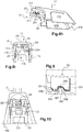
- the front wall 172 is for example shaped to allow mounting on the wiper blade 3 and more specifically comprises a cutout 176 for the passage of the deflector 9 (see Figures 1 and 2 ).
- the cutout 176 is better visible on the figure 8c .
- This cutout 176 is formed substantially centrally on the front wall 172 in the transverse direction T.
- the cutout 176 is provided sufficiently wide to overcome the direction of the deflector 9 (or spoiler) in the direction to the right or left.
- the cutout 176 may for example have a width of the order of half of the total width of the front wall 172. Such a cutout 176 contributes to standardize the cover 17 which can adapt to different vehicles in terms of the style of brushes and arms as the type of direction.
- the rear wall 173 is in turn configured to be arranged on the side of the drive arm 5 (see Figures 1 and 2 ).
- the upper wall 171 is arranged facing the upper face 151 of the connector 15a or 15b
- the front wall 172 is arranged facing an end wall.
- the rear wall 173 is arranged facing the other end wall 153 of the connector 15a or 15b
- each side wall 174, 175 of the cover 17 is arranged facing a side face 154 , 155 of the connector 15a or 15b.
- the second sliding means 21 of the cover 17 are in this example carried by an upper part of the cover 17, here by the upper wall 171. More specifically, the second sliding means 21 are arranged on the upper wall 171 of the inner side of the hood 17, that is to say on the side of the upper wall 171 from which extend the side walls 174, 175, the inner side being intended to face the connector 15a or 15b assembly.
- the second sliding means 21 comprise at least one tongue 211 extending for example substantially longitudinally.
- the second sliding means 21 of the cover 17 comprise two longitudinal tongues 211, better visible on the Figures 8d to 8f , configured to cooperate with both the grooves 191 of the symmetrical connector 15a and the grooves 191, 191 'of the asymmetric connector 15b.
- each tab 211 extend here from the upper wall 171, on the inside of the cover 17 and protruding from the rear wall 173.
- each tab 211 has a substantially "L" shaped section.
- the cover 17 has two tabs 211 which come into the grooves 191; 191 'present on the connector 15a or 15b while passing over the adapter 33.
- the drive arm 5 attached to the adapter 33 is thus held in tear in the vertical direction V by the cover 17 and in particular its tabs 211, which lock the adapter 33 by preventing it from coming out from above.
- the cover 17 therefore exerts a resistance to a vertical force due to the presence of two tongues 211 taken in the grooves 191; 191 'present on the connector 15a or 15b.
- the cover 17 comprises at least one flexible or flexible element.
- the side walls 174, 175 of the cover 17 are at least partially flexible.
- the cover 17 then forms a gripping member configured to deform in a reversible manner, under the action of an external force, here when a user presses on the side walls 174, 175 of the cover 17.
- the second locking means 25 are carried by the two opposite side walls 174, 175 of the cover 17, more precisely here on an upper part of the walls. 174, 175 and below the second sliding means 21.
- the second sliding means 21 and the second locking means 25 are therefore provided at separate locations of the cover 17 while being made in one piece with the cover 17.
- the at least partially flexible sidewalls 174, 175 and which carry the second locking means 25 are configured to deform so as to allow the locking or unlocking of the cover 17 and the connector 15a or 15b.
- the connector 15a or 15b comprises such a flexible element carrying the first locking means 23.
- the cover 17 comprises at least one attachment tab 252, here at least two attachment tabs 252, each protruding from a side wall 174, 175.
- Each attachment tab 252 extends from the side wall 174 , respectively 175, inside the cover 17 and in a direction substantially perpendicular to the side face 174, respectively 175.
- Each hooking lug 252 is bent so as to form at its free end a hook 251 configured to fit in an opening 231 complementary to the connector 15a or 15b.
- Each hook 251 is arranged substantially at the height of the corresponding opening 231 to hook on the connector 15a or 15b in the assembled state. Once the hooks 251 engaged in the openings 231 associated, it allows to limit the relative longitudinal displacement between the connector 15a or 15b and the cover 17, and thus to prevent longitudinal tearing.
- the cover 17 comprises two flexible walls, here the side walls 174, 175, which support inside two hooks 251 which are fixed, once the cover 17 and the connector 15a or 15 assembled, in the openings 231 of the connector 15a or 15b provided for this purpose.
- the second holding means 29 carried by the cover 17 are arranged on the upper wall 171 of the cover 17, on the inside of the cover 17 intended to face the connector 15a or 15b.
- the cover 17 comprises at least one plate 291 forming a second holding means 29, extending substantially perpendicular to the upper wall 171 towards the inside of the cover 17.
- the cover 17 comprises minus two plates 291 parallel to each other, three in the illustrated example.
- the or each plate 291 is shaped to cooperate with one or more stops 271 of the connector 15a or 15b.
- the or each plate 291 has a notch 292.
- This notch 292 here confers on the wafer 291 a shape substantially "U", with a first branch 293 and a second branch 294 connected by a base 295.
- the stop or stops 271 are located at the notch 292, between the two branches 293, 294 of the plates 291.
- the displacement of the connector 15a or 15b with respect to the cover 17 is limited by the two branches 293, 294 of the one or more plates 291 along the axis of sliding A, here in the longitudinal direction L.
- the size of the notch 292, or in other words the spacing between the two branches 293, 294 can be provided so that, in the delivery position, there is clearance between an abutment 271 and the branches 293 and 294.
- the first branch 293 has a leading edge 296 configured to be the first edge in contact with at least one stop 271 when the assembly of the cover 17 to the connector ur 15a or 15b.
- This leading edge 296 may be a bevel to facilitate the passage of the stop 271 to the notch 292 between the two branches 293 and 294.
- the first leg 293 may have a substantially straight trailing edge 297.
- the second branch 294 can in turn have a leading edge 298 inclined relative to the base 295, for example here with the same inclination as the bevel 296 of the first branch 293 to facilitate the continuation of the sliding movement of the or stops 271 out of the notch 292.
- the second or the second holding means 29 may additionally be configured to cooperate with the adapter 33, coming here to press the adapter 33, in the final assembled position of the cover 17 and the connector 15a or 15b, so as to immobilize the adapter 33 in one direction substantially perpendicular to the sliding axis A, here in the vertical direction V.
- the tongues 291 then provide two functions. The first is to maintain the cover 17 on the connector 15a or 15b in the open position, so that the end consumer has a windshield wiper 3 ready to mount without any room to add. The second is to come and press the adapter 33 and put it in constraint to hold it in the connector 15a or 15b.
- the tabs 211 of the cover 17 can be inserted into the corresponding grooves 191 of the connector 15a or 15b to the delivery position, that is to say when the first and second holding means 27, 29 cooperate.
- the end user can then use the fixing device 7 fixed on the wiper blade 3, connect it to the drive arm 5, in particular via the adapter 33 and continue the sliding movement.
- the hooks 251 of the cover 17 fit into the openings 231 on the lateral faces 154, 155 of the connector 15a or 15b thus limiting the relative longitudinal displacement between the connector 15a or 15b and the cover 17.
- the tabs 211 of the cover 17 are moved to above the adapter 33 thus preventing vertical tearing and in addition the pads 291 of the cover 17 advantageously press the adapter 33.
- the fixing device 7 is advantageously all plastic and can be made simply at a lower cost while ensuring a connection and a reliable and robust locking.
- the second sliding means 21 and locking 25, or even retaining 29, are made in one piece plastic with the cover 17 while being in different parts of the cover 17. It thus facilitates the realization of the piece and this improves the assembly and disassembly on the connector 15a or 15b.
- the cover 17 is suitable for both left and right steering vehicles, which reduces the number of covers at the production stage.
- the first sliding means 19 and locking 23, or even holding 27, are made in one piece plastic with the connector 15a or 15b while being in different locations of the connector 15a or 15b.
Claims (16)
- Befestigungsvorrichtung (7) für die Montage eines Scheibenwischerblatts (3) eines Wischsystems (1) für Kraftfahrzeug auf einem Scheibenwischerarm (5), wobei die Befestigungsvorrichtung (7) Folgendes umfasst:- einen Steckverbinder (15a; 15b), der eine Längshauptausdehnungsform aufweist und konfiguriert ist, um mit dem Scheibenwischerblatt (3) einerseits und dem Scheibenwischerarm (5) andererseits verbunden zu sein und Folgendes umfasst:• mindestens ein erstes Gleitmittel (19) durch Längsverschiebung und• mindestens ein erstes Verriegelungsmittel (23), und- eine Haube (17), die eine Längshauptausdehnungsform aufweist und konfiguriert ist, um mit dem Steckverbinder (15a; 15b) derart zusammenzuwirken, dass das Scheibenwischerblatt (3) an dem Scheibenwischerarm (5) befestigt ist, und Folgendes umfasst:dadurch gekennzeichnet, dass:• mindestens ein zweites Gleitmittel (21) durch Längsverschiebung, das zu dem mindestens einen ersten Gleitmittel (19) komplementär ist, und• mindestens ein zweites Verriegelungsmittel (25), das zu dem mindestens einen ersten Verriegelungsmittel (23) komplementär ist,- die ersten Gleitmittel (19) und Verriegelungsmittel (23) aus einem einzigen Stück mit dem Steckverbinder (15a; 15b) hergestellt sind, und dass- die zweiten Gleitmittel (21) und Verriegelungsmittel (25) aus einem einzigen Stück mit der Haube (17) hergestellt sind, und dass- das mindestens eine zweite Gleitmittel (21) von dem mindestens einen zweiten Verriegelungsmittel (25) getrennt ist.
- Befestigungsvorrichtung (7) nach dem vorstehenden Anspruch, wobei der Steckverbinder (15a; 15b) und die Haube (17) aus Kunststoffen hergestellt sind.
- Befestigungsvorrichtung (7) nach einem der vorstehenden Ansprüche, wobei:- das erste und das zweite komplementäre Gleitmittel (19, 21) jeweils von einem oberen Teil des Steckverbinders (15a; 15b) und von einem oberen Teil der Haube (17) getragen werden, und wobei- das erste und das zweite komplementäre Verriegelungsmittel (23, 25) jeweils von entgegengesetzten Seitenflächen (154, 155) des Steckverbinders (15a; 15b) und von zwei entgegengesetzten Seitenwänden (174, 175) der Haube (17) getragen werden, indem sie sich in dem Inneren der Haube (17) erstrecken.
- Befestigungsvorrichtung (7) nach einem der vorstehenden Ansprüche, wobei das erste und das zweite komplementäre Befestigungsmittel (23, 25) mindestens einen Haken (251) und mindestens eine dazugehörende Öffnung (231), in die sich der Haken (251) konfigurationsgemäß einfügt, umfassen.
- Befestigungsvorrichtung (7) nach dem vorstehenden Anspruch, wobei:- die Haube (17) mindestens zwei Aufhängpratzen (252) umfasst, die sich längs erstrecken und jeweils in einem Haken (251) enden, und- der Steckverbinder (15a; 15b) mindestens zwei Öffnungen (231) aufweist, in die die Haken (251) konfigurationsgemäß für das Verriegeln der Haube (17) an dem Steckverbinder (15a; 15b) eingreifen.
- Befestigungsvorrichtung (7) nach einem der vorstehenden Ansprüche, wobei die Haube (17) mindestens ein biegsames Element umfasst, das das mindestens eine zweite Verriegelungsmittel (23; 25) trägt und konfiguriert ist, um sich derart zu verformen, dass das Verriegeln oder das Entriegeln der Haube (17) und des Steckverbinders (15a; 15b) erlaubt wird.
- Befestigungsvorrichtung (7) nach einem der vorstehenden Ansprüche, wobei die Haube (17) und der Steckverbinder (15a; 15b) konfiguriert sind, um zueinander entlang einer Gleitachse (A) zu gleiten, und wobei die ersten und zweiten komplementären Gleitmittel (19, 21) derart ausgestaltet sind, dass sie ein Abreißen der Haube (17) und/oder des Steckverbinders (15a; 15b) entlang einer Richtung senkrecht zu der Gleitachse (A) verhindern.
- Befestigungsvorrichtung (7) nach einem der vorstehenden Ansprüche, wobei das erste und das zweite komplementäre Gleitmittel (19, 21) mindestens eine Lasche (211) und mindestens eine dazugehörende Nut (191), in der die Lasche (211) konfigurationsgemäß gleitet, umfassen.
- Befestigungsvorrichtung (7) nach dem vorstehenden Anspruch, wobei:- die Haube (17) mindestens zwei Laschen (211) umfasst, die sich längs erstrecken, und- der Steckverbinder (15a; 15b) mindestens zwei dazugehörende Nuten (191) umfasst, so dass beim Zusammenfügen die Laschen (211) der Haube (17) durch Längsverschiebung in den Nuten (191) des Steckverbinders (15a; 15b) gleiten.
- Befestigungsvorrichtung (7) nach einem der vorstehenden Ansprüche, wobei die Haube (17) einen Ausschnitt (176) für das Durchgehen des Scheibenwischerblatts (3) umfasst, wobei der Ausschnitt bevorzugt eine Breite größer als 6 mm, insbesondere in der Größenordnung von 9 mm besitzt.
- Befestigungsvorrichtung (7) nach einem der vorstehenden Ansprüche,- die mindestens ein erstes (27) und mindestens ein zweites (29) komplementäres Haltemittel umfasst, die jeweils von dem Steckverbinder (15a; 15b) und von der Haube (17) getragen werden,- wobei das erste und zweite Haltemittel (27, 29) konfiguriert sind, um die Haube (17) und den Steckverbinder (15a; 15b) in einer Lieferposition ohne Zusammenwirken des ersten und zweiten Verriegelungsmittels (23, 25) zu halten.
- Befestigungsvorrichtung (7) nach dem vorstehenden Anspruch, wobei das erste und das zweite Haltemittel (27, 29) mindestens einen Anschlag (271) und mindestens eine dazugehörende Platte (291) umfassen.
- Befestigungsvorrichtung (7) nach dem vorstehenden Anspruch, wobei- sich die mindestens eine Platte (291) von einer oberen Wand (171) der Haube (17) zu dem Inneren der Haube (17) erstreckt, und wobei- der mindestens eine Anschlag (271) an der Verbindung zwischen einer oberen Fläche (151) und einer Endfläche (152, 153) des Steckverbinders (15a; 15b) eingerichtet ist.
- Befestigungsvorrichtung (7) nach einem der Ansprüche 12 oder 13, wobei die mindestens eine Platte (291) im Wesentlichen eine "U"-Form aufweist, die zwei Schenkel (293, 294) umfasst, zwischen welchen der Anschlag (271) in der Lieferposition eingerichtet ist, so dass die Verlagerung des Steckverbinders (15a; 15b) bezüglich der Haube (17) entlang der Gleitachse (A) zwischen den zwei Schenkeln (293, 294) des "U" der mindestens einen Platte (291) beschränkt ist.
- Befestigungsvorrichtung (7) nach einem der vorstehenden Ansprüche 11 bis 14,- die einen Adapter (33) für die Befestigung an dem Scheibenwischerarm (5) umfasst,- wobei der Steckverbinder (15a; 15b) eine Aufnahme (34) zum Aufnehmen des Adapters (33) umfasst, und- wobei das mindestens eine zweite Haltemittel (29), das von der Haube (17) getragen wird, konfiguriert ist, um den Adapter (33) entlang einer Richtung, die im Wesentlichen zu der Gleitachse (A) in der verriegelten Position der Haube (17) und des Steckverbinders (15a; 15b) senkrecht ist, stillgestellt ist.
- Kraftfahrzeug-Wischsystem, das mindestens ein Scheibenwischerblatt (3) und mindestens einen Scheibenwischerarm (5) des Scheibenwischerblatts (3) umfasst, dadurch gekennzeichnet, dass es außerdem eine Befestigungsvorrichtung (7) nach einem der vorstehenden Ansprüche umfasst, die das Scheibenwischerblatt (3) an dem Scheibenwischerarm (5) befestigt.
Applications Claiming Priority (1)
| Application Number | Priority Date | Filing Date | Title |
|---|---|---|---|
| FR1654769A FR3051749B1 (fr) | 2016-05-27 | 2016-05-27 | Dispositif de fixation pour le montage d'un balai d'essuie-glace sur un bras d'entrainement, et systeme d'essuyage correspondant |
Publications (2)
| Publication Number | Publication Date |
|---|---|
| EP3248848A1 EP3248848A1 (de) | 2017-11-29 |
| EP3248848B1 true EP3248848B1 (de) | 2019-08-21 |
Family
ID=56802613
Family Applications (1)
| Application Number | Title | Priority Date | Filing Date |
|---|---|---|---|
| EP17170969.4A Active EP3248848B1 (de) | 2016-05-27 | 2017-05-15 | Befestigungsvorrichtung für die montage eines scheibenwischerblatts auf einem scheibenwischerarm, und entsprechendes scheibenwischsystem |
Country Status (3)
| Country | Link |
|---|---|
| EP (1) | EP3248848B1 (de) |
| CN (1) | CN107433931B (de) |
| FR (1) | FR3051749B1 (de) |
Family Cites Families (4)
| Publication number | Priority date | Publication date | Assignee | Title |
|---|---|---|---|---|
| DE10122764B4 (de) * | 2001-05-10 | 2016-08-25 | Valeo Auto-Electric Wischer Und Motoren Gmbh | Wischvorrichtung |
| DE102010052315B4 (de) * | 2010-11-16 | 2016-01-21 | Daimler Ag | Verbindungsanordnung und Verfahren zum Verbinden eines Wischblatts mit einem Wischarm für eine Scheibenwischanlage eines Fahrzeug |
| CN202255438U (zh) * | 2011-10-10 | 2012-05-30 | 郑州日产汽车有限公司 | 汽车前风挡玻璃固定装置 |
| FR3025768A1 (fr) * | 2014-09-15 | 2016-03-18 | Valeo Systemes Dessuyage | Organe pour un systeme de connexion d'un balai a un bras d'essuie-glace |
-
2016
- 2016-05-27 FR FR1654769A patent/FR3051749B1/fr not_active Expired - Fee Related
-
2017
- 2017-05-15 EP EP17170969.4A patent/EP3248848B1/de active Active
- 2017-05-27 CN CN201710388647.XA patent/CN107433931B/zh active Active
Non-Patent Citations (1)
| Title |
|---|
| None * |
Also Published As
| Publication number | Publication date |
|---|---|
| CN107433931B (zh) | 2020-06-02 |
| EP3248848A1 (de) | 2017-11-29 |
| FR3051749B1 (fr) | 2018-06-15 |
| FR3051749A1 (fr) | 2017-12-01 |
| CN107433931A (zh) | 2017-12-05 |
Similar Documents
| Publication | Publication Date | Title |
|---|---|---|
| EP1833708B1 (de) | Anpassbarer windschutzscheiben-flachwischer und zugehöriges lösbares verbindungsteil | |
| EP1140592B1 (de) | Kraftfahzeugscheibenwischer mit einer verbesserten gelenkverbindung zwischen dem wischerblatt und dem wischerarm | |
| EP1924470B1 (de) | Arretierung zwischen einem wischblatt und scheibenwischerarm | |
| EP1098797B1 (de) | Kraftfahrzeugscheibenwischer mit schwenkbarem riegel | |
| EP1937524B1 (de) | Verbinder zum montieren und verbinden eines wischblattes mit einem antriebsarmende | |
| EP3118070B1 (de) | Organ für ein verbindungssystem eines wischerblatts | |
| EP3112223B1 (de) | Organ für ein verbindungssystem eines wischerblatts an mehrere scheibenwischerarme | |
| EP3251905B1 (de) | Anschlussadapter des freien endabschnitts eines scheibenwischerarms, und anordnung, die einen solchen adapter und einen scheibenwischerarm umfasst | |
| EP3112227B1 (de) | Adapter zum verbinden eines scheibenwischers mit einem antriebsarm | |
| EP3081439B1 (de) | Endstück für scheibenwischer | |
| EP3251904A1 (de) | Anschlussadapter des freien endabschnitts eines scheibenwischerarms, und anordnung, die einen solchen adapter und einen scheibenwischerarm umfasst | |
| EP3248848B1 (de) | Befestigungsvorrichtung für die montage eines scheibenwischerblatts auf einem scheibenwischerarm, und entsprechendes scheibenwischsystem | |
| EP3112224A1 (de) | Adapter zum verbinden eines scheibenwischers mit einem antriebsarm | |
| FR2689837A1 (fr) | Dispositif d'essuie-glace incorporant un déflecteur. | |
| WO2022017806A1 (fr) | Dispositif de connexion d'un balai d'essuyage à un bras d'essuie-glace | |
| EP3375675B1 (de) | Abdeckung, verbindungsvorrichtung für die montage eines scheibenwischerblatts auf einem entsprechenden scheibenwischerarm, und entsprechendes scheibenwischsystem | |
| EP1729019B1 (de) | Anordnung der Halterung einer Befestigungsmutter einer Komponente wie etwa ein Fahrzeugsitz | |
| EP3902721A1 (de) | Adapter für ein wischerblatt eines kraftfahrzeugs | |
| EP3112228B1 (de) | Organ für ein verbindungssystem eines wischerblatts an einen scheibenwischerarm | |
| EP3112226B1 (de) | Organ für ein verbindungssystem eines wischerblatts an einen scheibenwischerarm | |
| EP3366532A1 (de) | Anpassbares endstück für scheibenwischer | |
| FR2801551A1 (fr) | Essuie-glace de vehicule automobile comportant un verrou pivotant et des moyens perfectionnes de retenue du connecteur d'articulation du balai | |
| FR3091228A1 (fr) | système d'essuyage pour véhicule automobile | |
| FR3110205A1 (fr) | Dispositif de fixation modulaire pour une paroi, notamment une paroi intérieure de véhicule automobile | |
| EP3902719A1 (de) | Adapter für scheibenwischerblatt eines kraftfahrzeugs |
Legal Events
| Date | Code | Title | Description |
|---|---|---|---|
| PUAI | Public reference made under article 153(3) epc to a published international application that has entered the european phase |
Free format text: ORIGINAL CODE: 0009012 |
|
| STAA | Information on the status of an ep patent application or granted ep patent |
Free format text: STATUS: REQUEST FOR EXAMINATION WAS MADE |
|
| 17P | Request for examination filed |
Effective date: 20170515 |
|
| AK | Designated contracting states |
Kind code of ref document: A1 Designated state(s): AL AT BE BG CH CY CZ DE DK EE ES FI FR GB GR HR HU IE IS IT LI LT LU LV MC MK MT NL NO PL PT RO RS SE SI SK SM TR |
|
| AX | Request for extension of the european patent |
Extension state: BA ME |
|
| STAA | Information on the status of an ep patent application or granted ep patent |
Free format text: STATUS: EXAMINATION IS IN PROGRESS |
|
| 17Q | First examination report despatched |
Effective date: 20180823 |
|
| GRAP | Despatch of communication of intention to grant a patent |
Free format text: ORIGINAL CODE: EPIDOSNIGR1 |
|
| STAA | Information on the status of an ep patent application or granted ep patent |
Free format text: STATUS: GRANT OF PATENT IS INTENDED |
|
| INTG | Intention to grant announced |
Effective date: 20190326 |
|
| GRAS | Grant fee paid |
Free format text: ORIGINAL CODE: EPIDOSNIGR3 |
|
| GRAA | (expected) grant |
Free format text: ORIGINAL CODE: 0009210 |
|
| STAA | Information on the status of an ep patent application or granted ep patent |
Free format text: STATUS: THE PATENT HAS BEEN GRANTED |
|
| AK | Designated contracting states |
Kind code of ref document: B1 Designated state(s): AL AT BE BG CH CY CZ DE DK EE ES FI FR GB GR HR HU IE IS IT LI LT LU LV MC MK MT NL NO PL PT RO RS SE SI SK SM TR |
|
| REG | Reference to a national code |
Ref country code: GB Ref legal event code: FG4D Free format text: NOT ENGLISH |
|
| REG | Reference to a national code |
Ref country code: CH Ref legal event code: EP |
|
| REG | Reference to a national code |
Ref country code: DE Ref legal event code: R096 Ref document number: 602017006258 Country of ref document: DE |
|
| REG | Reference to a national code |
Ref country code: AT Ref legal event code: REF Ref document number: 1169377 Country of ref document: AT Kind code of ref document: T Effective date: 20190915 |
|
| REG | Reference to a national code |
Ref country code: IE Ref legal event code: FG4D Free format text: LANGUAGE OF EP DOCUMENT: FRENCH |
|
| REG | Reference to a national code |
Ref country code: LT Ref legal event code: MG4D |
|
| REG | Reference to a national code |
Ref country code: NL Ref legal event code: MP Effective date: 20190821 |
|
| PG25 | Lapsed in a contracting state [announced via postgrant information from national office to epo] |
Ref country code: LT Free format text: LAPSE BECAUSE OF FAILURE TO SUBMIT A TRANSLATION OF THE DESCRIPTION OR TO PAY THE FEE WITHIN THE PRESCRIBED TIME-LIMIT Effective date: 20190821 Ref country code: FI Free format text: LAPSE BECAUSE OF FAILURE TO SUBMIT A TRANSLATION OF THE DESCRIPTION OR TO PAY THE FEE WITHIN THE PRESCRIBED TIME-LIMIT Effective date: 20190821 Ref country code: NL Free format text: LAPSE BECAUSE OF FAILURE TO SUBMIT A TRANSLATION OF THE DESCRIPTION OR TO PAY THE FEE WITHIN THE PRESCRIBED TIME-LIMIT Effective date: 20190821 Ref country code: BG Free format text: LAPSE BECAUSE OF FAILURE TO SUBMIT A TRANSLATION OF THE DESCRIPTION OR TO PAY THE FEE WITHIN THE PRESCRIBED TIME-LIMIT Effective date: 20191121 Ref country code: SE Free format text: LAPSE BECAUSE OF FAILURE TO SUBMIT A TRANSLATION OF THE DESCRIPTION OR TO PAY THE FEE WITHIN THE PRESCRIBED TIME-LIMIT Effective date: 20190821 Ref country code: HR Free format text: LAPSE BECAUSE OF FAILURE TO SUBMIT A TRANSLATION OF THE DESCRIPTION OR TO PAY THE FEE WITHIN THE PRESCRIBED TIME-LIMIT Effective date: 20190821 Ref country code: PT Free format text: LAPSE BECAUSE OF FAILURE TO SUBMIT A TRANSLATION OF THE DESCRIPTION OR TO PAY THE FEE WITHIN THE PRESCRIBED TIME-LIMIT Effective date: 20191223 Ref country code: NO Free format text: LAPSE BECAUSE OF FAILURE TO SUBMIT A TRANSLATION OF THE DESCRIPTION OR TO PAY THE FEE WITHIN THE PRESCRIBED TIME-LIMIT Effective date: 20191121 |
|
| PG25 | Lapsed in a contracting state [announced via postgrant information from national office to epo] |
Ref country code: RS Free format text: LAPSE BECAUSE OF FAILURE TO SUBMIT A TRANSLATION OF THE DESCRIPTION OR TO PAY THE FEE WITHIN THE PRESCRIBED TIME-LIMIT Effective date: 20190821 Ref country code: IS Free format text: LAPSE BECAUSE OF FAILURE TO SUBMIT A TRANSLATION OF THE DESCRIPTION OR TO PAY THE FEE WITHIN THE PRESCRIBED TIME-LIMIT Effective date: 20191221 Ref country code: ES Free format text: LAPSE BECAUSE OF FAILURE TO SUBMIT A TRANSLATION OF THE DESCRIPTION OR TO PAY THE FEE WITHIN THE PRESCRIBED TIME-LIMIT Effective date: 20190821 Ref country code: GR Free format text: LAPSE BECAUSE OF FAILURE TO SUBMIT A TRANSLATION OF THE DESCRIPTION OR TO PAY THE FEE WITHIN THE PRESCRIBED TIME-LIMIT Effective date: 20191122 Ref country code: LV Free format text: LAPSE BECAUSE OF FAILURE TO SUBMIT A TRANSLATION OF THE DESCRIPTION OR TO PAY THE FEE WITHIN THE PRESCRIBED TIME-LIMIT Effective date: 20190821 Ref country code: AL Free format text: LAPSE BECAUSE OF FAILURE TO SUBMIT A TRANSLATION OF THE DESCRIPTION OR TO PAY THE FEE WITHIN THE PRESCRIBED TIME-LIMIT Effective date: 20190821 |
|
| REG | Reference to a national code |
Ref country code: AT Ref legal event code: MK05 Ref document number: 1169377 Country of ref document: AT Kind code of ref document: T Effective date: 20190821 |
|
| PG25 | Lapsed in a contracting state [announced via postgrant information from national office to epo] |
Ref country code: TR Free format text: LAPSE BECAUSE OF FAILURE TO SUBMIT A TRANSLATION OF THE DESCRIPTION OR TO PAY THE FEE WITHIN THE PRESCRIBED TIME-LIMIT Effective date: 20190821 |
|
| PG25 | Lapsed in a contracting state [announced via postgrant information from national office to epo] |
Ref country code: AT Free format text: LAPSE BECAUSE OF FAILURE TO SUBMIT A TRANSLATION OF THE DESCRIPTION OR TO PAY THE FEE WITHIN THE PRESCRIBED TIME-LIMIT Effective date: 20190821 Ref country code: EE Free format text: LAPSE BECAUSE OF FAILURE TO SUBMIT A TRANSLATION OF THE DESCRIPTION OR TO PAY THE FEE WITHIN THE PRESCRIBED TIME-LIMIT Effective date: 20190821 Ref country code: PL Free format text: LAPSE BECAUSE OF FAILURE TO SUBMIT A TRANSLATION OF THE DESCRIPTION OR TO PAY THE FEE WITHIN THE PRESCRIBED TIME-LIMIT Effective date: 20190821 Ref country code: DK Free format text: LAPSE BECAUSE OF FAILURE TO SUBMIT A TRANSLATION OF THE DESCRIPTION OR TO PAY THE FEE WITHIN THE PRESCRIBED TIME-LIMIT Effective date: 20190821 Ref country code: RO Free format text: LAPSE BECAUSE OF FAILURE TO SUBMIT A TRANSLATION OF THE DESCRIPTION OR TO PAY THE FEE WITHIN THE PRESCRIBED TIME-LIMIT Effective date: 20190821 Ref country code: IT Free format text: LAPSE BECAUSE OF FAILURE TO SUBMIT A TRANSLATION OF THE DESCRIPTION OR TO PAY THE FEE WITHIN THE PRESCRIBED TIME-LIMIT Effective date: 20190821 |
|
| PG25 | Lapsed in a contracting state [announced via postgrant information from national office to epo] |
Ref country code: SM Free format text: LAPSE BECAUSE OF FAILURE TO SUBMIT A TRANSLATION OF THE DESCRIPTION OR TO PAY THE FEE WITHIN THE PRESCRIBED TIME-LIMIT Effective date: 20190821 Ref country code: SK Free format text: LAPSE BECAUSE OF FAILURE TO SUBMIT A TRANSLATION OF THE DESCRIPTION OR TO PAY THE FEE WITHIN THE PRESCRIBED TIME-LIMIT Effective date: 20190821 Ref country code: IS Free format text: LAPSE BECAUSE OF FAILURE TO SUBMIT A TRANSLATION OF THE DESCRIPTION OR TO PAY THE FEE WITHIN THE PRESCRIBED TIME-LIMIT Effective date: 20200224 Ref country code: CZ Free format text: LAPSE BECAUSE OF FAILURE TO SUBMIT A TRANSLATION OF THE DESCRIPTION OR TO PAY THE FEE WITHIN THE PRESCRIBED TIME-LIMIT Effective date: 20190821 |
|
| REG | Reference to a national code |
Ref country code: DE Ref legal event code: R097 Ref document number: 602017006258 Country of ref document: DE |
|
| PLBE | No opposition filed within time limit |
Free format text: ORIGINAL CODE: 0009261 |
|
| STAA | Information on the status of an ep patent application or granted ep patent |
Free format text: STATUS: NO OPPOSITION FILED WITHIN TIME LIMIT |
|
| PG2D | Information on lapse in contracting state deleted |
Ref country code: IS |
|
| 26N | No opposition filed |
Effective date: 20200603 |
|
| PG25 | Lapsed in a contracting state [announced via postgrant information from national office to epo] |
Ref country code: SI Free format text: LAPSE BECAUSE OF FAILURE TO SUBMIT A TRANSLATION OF THE DESCRIPTION OR TO PAY THE FEE WITHIN THE PRESCRIBED TIME-LIMIT Effective date: 20190821 |
|
| PG25 | Lapsed in a contracting state [announced via postgrant information from national office to epo] |
Ref country code: LI Free format text: LAPSE BECAUSE OF NON-PAYMENT OF DUE FEES Effective date: 20200531 Ref country code: MC Free format text: LAPSE BECAUSE OF FAILURE TO SUBMIT A TRANSLATION OF THE DESCRIPTION OR TO PAY THE FEE WITHIN THE PRESCRIBED TIME-LIMIT Effective date: 20190821 Ref country code: CH Free format text: LAPSE BECAUSE OF NON-PAYMENT OF DUE FEES Effective date: 20200531 |
|
| PG25 | Lapsed in a contracting state [announced via postgrant information from national office to epo] |
Ref country code: LU Free format text: LAPSE BECAUSE OF NON-PAYMENT OF DUE FEES Effective date: 20200515 |
|
| PG25 | Lapsed in a contracting state [announced via postgrant information from national office to epo] |
Ref country code: IE Free format text: LAPSE BECAUSE OF NON-PAYMENT OF DUE FEES Effective date: 20200515 |
|
| PG25 | Lapsed in a contracting state [announced via postgrant information from national office to epo] |
Ref country code: MT Free format text: LAPSE BECAUSE OF FAILURE TO SUBMIT A TRANSLATION OF THE DESCRIPTION OR TO PAY THE FEE WITHIN THE PRESCRIBED TIME-LIMIT Effective date: 20190821 Ref country code: CY Free format text: LAPSE BECAUSE OF FAILURE TO SUBMIT A TRANSLATION OF THE DESCRIPTION OR TO PAY THE FEE WITHIN THE PRESCRIBED TIME-LIMIT Effective date: 20190821 |
|
| PG25 | Lapsed in a contracting state [announced via postgrant information from national office to epo] |
Ref country code: MK Free format text: LAPSE BECAUSE OF FAILURE TO SUBMIT A TRANSLATION OF THE DESCRIPTION OR TO PAY THE FEE WITHIN THE PRESCRIBED TIME-LIMIT Effective date: 20190821 |
|
| P01 | Opt-out of the competence of the unified patent court (upc) registered |
Effective date: 20230528 |
|
| PGFP | Annual fee paid to national office [announced via postgrant information from national office to epo] |
Ref country code: FR Payment date: 20230523 Year of fee payment: 7 Ref country code: DE Payment date: 20230510 Year of fee payment: 7 |
|
| PGFP | Annual fee paid to national office [announced via postgrant information from national office to epo] |
Ref country code: BE Payment date: 20230515 Year of fee payment: 7 |
|
| PGFP | Annual fee paid to national office [announced via postgrant information from national office to epo] |
Ref country code: GB Payment date: 20230519 Year of fee payment: 7 |