EP3112224A1 - Adapter zum verbinden eines scheibenwischers mit einem antriebsarm - Google Patents
Adapter zum verbinden eines scheibenwischers mit einem antriebsarm Download PDFInfo
- Publication number
- EP3112224A1 EP3112224A1 EP16176399.0A EP16176399A EP3112224A1 EP 3112224 A1 EP3112224 A1 EP 3112224A1 EP 16176399 A EP16176399 A EP 16176399A EP 3112224 A1 EP3112224 A1 EP 3112224A1
- Authority
- EP
- European Patent Office
- Prior art keywords
- adapter
- arm
- strips
- wiper blade
- longitudinal
- Prior art date
- Legal status (The legal status is an assumption and is not a legal conclusion. Google has not performed a legal analysis and makes no representation as to the accuracy of the status listed.)
- Withdrawn
Links
Images


Classifications
-
- B—PERFORMING OPERATIONS; TRANSPORTING
- B60—VEHICLES IN GENERAL
- B60S—SERVICING, CLEANING, REPAIRING, SUPPORTING, LIFTING, OR MANOEUVRING OF VEHICLES, NOT OTHERWISE PROVIDED FOR
- B60S1/00—Cleaning of vehicles
- B60S1/02—Cleaning windscreens, windows or optical devices
- B60S1/04—Wipers or the like, e.g. scrapers
- B60S1/32—Wipers or the like, e.g. scrapers characterised by constructional features of wiper blade arms or blades
- B60S1/40—Connections between blades and arms
- B60S1/4038—Connections between blades and arms for arms provided with a channel-shaped end
- B60S1/4041—Connections between blades and arms for arms provided with a channel-shaped end the channel-shaped end comprising a pivot pin mounted between the side walls
-
- B—PERFORMING OPERATIONS; TRANSPORTING
- B60—VEHICLES IN GENERAL
- B60S—SERVICING, CLEANING, REPAIRING, SUPPORTING, LIFTING, OR MANOEUVRING OF VEHICLES, NOT OTHERWISE PROVIDED FOR
- B60S1/00—Cleaning of vehicles
- B60S1/02—Cleaning windscreens, windows or optical devices
- B60S1/04—Wipers or the like, e.g. scrapers
- B60S1/32—Wipers or the like, e.g. scrapers characterised by constructional features of wiper blade arms or blades
- B60S1/38—Wiper blades
- B60S1/3806—Means, or measures taken, for influencing the aerodynamic quality of the wiper blades
-
- B—PERFORMING OPERATIONS; TRANSPORTING
- B60—VEHICLES IN GENERAL
- B60S—SERVICING, CLEANING, REPAIRING, SUPPORTING, LIFTING, OR MANOEUVRING OF VEHICLES, NOT OTHERWISE PROVIDED FOR
- B60S1/00—Cleaning of vehicles
- B60S1/02—Cleaning windscreens, windows or optical devices
- B60S1/04—Wipers or the like, e.g. scrapers
- B60S1/32—Wipers or the like, e.g. scrapers characterised by constructional features of wiper blade arms or blades
- B60S1/38—Wiper blades
- B60S1/3848—Flat-type wiper blade, i.e. without harness
- B60S1/3849—Connectors therefor; Connection to wiper arm; Attached to blade
- B60S1/3851—Mounting of connector to blade assembly
- B60S1/3853—Snap-fit, e.g. elastic connection
-
- B—PERFORMING OPERATIONS; TRANSPORTING
- B60—VEHICLES IN GENERAL
- B60S—SERVICING, CLEANING, REPAIRING, SUPPORTING, LIFTING, OR MANOEUVRING OF VEHICLES, NOT OTHERWISE PROVIDED FOR
- B60S1/00—Cleaning of vehicles
- B60S1/02—Cleaning windscreens, windows or optical devices
- B60S1/04—Wipers or the like, e.g. scrapers
- B60S1/32—Wipers or the like, e.g. scrapers characterised by constructional features of wiper blade arms or blades
- B60S1/38—Wiper blades
- B60S1/3848—Flat-type wiper blade, i.e. without harness
- B60S1/3874—Flat-type wiper blade, i.e. without harness with a reinforcing vertebra
-
- B—PERFORMING OPERATIONS; TRANSPORTING
- B60—VEHICLES IN GENERAL
- B60S—SERVICING, CLEANING, REPAIRING, SUPPORTING, LIFTING, OR MANOEUVRING OF VEHICLES, NOT OTHERWISE PROVIDED FOR
- B60S1/00—Cleaning of vehicles
- B60S1/02—Cleaning windscreens, windows or optical devices
- B60S1/04—Wipers or the like, e.g. scrapers
- B60S1/32—Wipers or the like, e.g. scrapers characterised by constructional features of wiper blade arms or blades
- B60S1/38—Wiper blades
- B60S1/3848—Flat-type wiper blade, i.e. without harness
- B60S1/3886—End caps
- B60S1/3887—Mounting of end caps
-
- B—PERFORMING OPERATIONS; TRANSPORTING
- B60—VEHICLES IN GENERAL
- B60S—SERVICING, CLEANING, REPAIRING, SUPPORTING, LIFTING, OR MANOEUVRING OF VEHICLES, NOT OTHERWISE PROVIDED FOR
- B60S1/00—Cleaning of vehicles
- B60S1/02—Cleaning windscreens, windows or optical devices
- B60S1/04—Wipers or the like, e.g. scrapers
- B60S1/32—Wipers or the like, e.g. scrapers characterised by constructional features of wiper blade arms or blades
- B60S1/40—Connections between blades and arms
- B60S1/4003—Multi-purpose connections for two or more kinds of arm ends
-
- B—PERFORMING OPERATIONS; TRANSPORTING
- B60—VEHICLES IN GENERAL
- B60S—SERVICING, CLEANING, REPAIRING, SUPPORTING, LIFTING, OR MANOEUVRING OF VEHICLES, NOT OTHERWISE PROVIDED FOR
- B60S1/00—Cleaning of vehicles
- B60S1/02—Cleaning windscreens, windows or optical devices
- B60S1/04—Wipers or the like, e.g. scrapers
- B60S1/32—Wipers or the like, e.g. scrapers characterised by constructional features of wiper blade arms or blades
- B60S1/40—Connections between blades and arms
- B60S1/4038—Connections between blades and arms for arms provided with a channel-shaped end
- B60S1/4045—Connections between blades and arms for arms provided with a channel-shaped end comprising a detachable intermediate element mounted on the channel-shaped end
- B60S1/4048—Connections between blades and arms for arms provided with a channel-shaped end comprising a detachable intermediate element mounted on the channel-shaped end the element being provided with retention means co-operating with the channel-shaped end of the arm
-
- B—PERFORMING OPERATIONS; TRANSPORTING
- B60—VEHICLES IN GENERAL
- B60S—SERVICING, CLEANING, REPAIRING, SUPPORTING, LIFTING, OR MANOEUVRING OF VEHICLES, NOT OTHERWISE PROVIDED FOR
- B60S1/00—Cleaning of vehicles
- B60S1/02—Cleaning windscreens, windows or optical devices
- B60S1/04—Wipers or the like, e.g. scrapers
- B60S1/32—Wipers or the like, e.g. scrapers characterised by constructional features of wiper blade arms or blades
- B60S1/40—Connections between blades and arms
- B60S1/4067—Connections between blades and arms for arms provided with a side pin
- B60S1/407—Connections between blades and arms for arms provided with a side pin with means provided on the arm for locking the side pin
Definitions
- the present invention relates in particular to an adapter for connecting a wiper blade to a drive arm, in particular a motor vehicle.
- a car is conventionally equipped with windshield wipers to wash the windshield and to prevent the driver's vision from being disturbed.
- These wipers generally comprise a drive arm, performing an angular reciprocating movement, and elongate brushes, themselves carrying scraper blades made of an elastic material. These blades rub against the windshield and evacuate the water by bringing it out of the driver's field of vision.
- the brooms are made in the form, or, in a conventional version, articulated stirrups that hold the scraper blade in several discrete places by giving it a bend allowing it to marry the eventual curvature of the windshield, or, in a newer version called " flat blade” (for "flat blade”), a semi-rigid assembly that keeps the scraper blade along its length thanks to one or bending vertebrae to apply the broom on the bumper -brise without having to use stirrups.
- the blade is attached to the drive arm by a connector system including a connector and an adapter.
- the connector is a piece which is secured to the blade and which is usually attached directly to the scraper blade or the flat broom, while the adapter is secured to the arm.
- the adapter is an intermediate piece that allows the connection and attachment of the connector on the drive arm. It is generally configured to be engaged in a head or end piece in the form of a clevis and U-shaped cross section of the drive arm.
- the connector and the adapter each comprise hinge means configured to cooperate with means complementary to the other member, to define at least one transverse pivot axis of the connector vis-à-vis the adapter, which is a swiveling axis of the blade vis-à-vis the arm.
- one of the members, such as the connector generally comprises a substantially cylindrical physical axis which defines the axis of articulation and which is received in a housing of complementary shape to the other member.
- the adapter generally comprises a body configured to be engaged in the end piece of the arm so that the body extends at least partially between two substantially parallel lateral legs of the end piece.
- the body of the adapter is connected at one end to a head, on which the free end of the end piece abuts.
- the body of the adapter generally comprises an actuating button which is engaged by elastic latching in an orifice of the end piece, when the latter is in abutment on the head, to lock the adapter vis-à- screw the end piece in this position.
- An adapter allows to associate a broom to a particular type of end piece or arm.
- end pieces U section for example, there are several varieties. These varieties are very similar in appearance but differ from each other in size and in particular in their lateral widths or dimensions, the width of an end piece being defined by the distance between the lateral legs of the end piece and more precisely by the distance between the external faces of these lateral legs. They also vary by the positions of the orifices intended to cooperate with the push buttons of the adapter.
- the adapter can accidentally disassemble the connector due to a game at the axis of articulation of the adapter vis-à-vis the connector.
- the invention proposes an improvement to the prior art.
- the invention proposes for this purpose an adapter for connecting a wiper blade to a drive arm, the adapter comprising two longitudinal side walls spaced from each other so as to form between them at least one configured housing for at least partly receiving a connector of the wiper blade, at least one of the side walls comprising at least one orifice, said side wall further comprising a bearing means projecting from an outer face of the side wall , characterized in that the support means is traversed by at least one orifice, said support means being derived material with the outer face of the side wall.
- the adapter according to the invention can be used as universal adapter, as will be described in detail in the following, that is to say an adapter for at least two different drive arms, such as for example at minus one end arm or U-shaped end piece, at least one stem arm (generally without end piece), at least one side-lock arm, etc.
- the adapter according to the invention overcomes the problem of the prior art of accidental disassembly of the adapter.
- the projecting projection means allow a better maintenance, in particular lateral or transverse, of the adapter on the connector. They are configured to cooperate by support with complementary means of another element to prevent or limit deformation of the adapter. They can also be configured to stiffen the side walls of the adapter and reduce their flexibility.
- the invention also covers a first assembly comprising an adapter according to any one of the features presented above and a connector integral with the wiper blade.
- the invention also relates to a second assembly comprising an adapter as above and said connecting rod arm member which is configured to cover at least part of said adapter, wherein said connecting member comprises two longitudinal side walls for s extend substantially parallel to the side walls of the adapter, and having on their inner faces projecting means which are configured to abut in the transverse direction on the support means of the side walls of the adapter.
- the invention covers a wiper blade or drive arm, characterized in that it comprises or carries a adapter according to one of the features listed above, or a first or second set as evoked also.
- the invention covers a third assembly comprising a drive arm and an adapter as presented above, or a first and / or second assembly shown above, the drive arm comprising a transverse pin received in at least one adapter ports, and an L-shaped latch extending transversely along the spindle.
- the longitudinal or lateral names refer to the orientation of the wiper blade or the drive arm according to the invention.
- the longitudinal direction corresponds to the main axis of the wiper blade or the arm in which it extends
- the lateral orientations correspond to intersecting lines, that is to say which cross the longitudinal direction, in particular perpendicular to the longitudinal axis of the wiper blade or the arm in its plane of rotation.
- the names outside (or front) or inside (or back) are appreciated relative to the point of attachment of the wiper blade on the arm, the inner name corresponding to the part where the arm and a half broom extend, or relative to the attachment point of the arm to the vehicle.
- the directions referenced as higher or lower correspond to orientations perpendicular to the plane of rotation of the wiper blade, the lower denomination containing the plane of the windshield.
- a wiper 10 including a wiper blade 12 and a drive arm 14 of the wiper blade 12.
- the drive arm forms a wiper arm.
- the wiper blade 12 is preferably of the flat blade type and comprises a longitudinal body 16, a wiper blade 18, generally of rubber, and at least one vertebra which stiffens the blade and promotes its application on a windshield of vehicle.
- the body 16 of the wiper blade 12 may include an upper aerodynamic deflector 20 for improving the operation of the wiper system, the purpose of this deflector being to improve the wiper blade plating on the windshield and therefore the aerodynamic performance of the windshield wiper.
- the wiper blade 12 may further comprise end tips 22 or hooking staples of the blade 18 and the vertebra on the body 16, these ends 22 being located at each of the longitudinal ends of the body 16.
- the wiper blade 12 comprises substantially in its middle an intermediate connector 24.
- An adapter 26 secured to the arm 14 is mounted on the connector 24 so as to maintain a degree of freedom in pivoting about an axis of articulation or pivoting Y which is a transverse axis substantially perpendicular to the longitudinal axis of the broom. 12. This degree of freedom allows pivoting of the wiper blade 12 vis-à-vis the arm 14 and thus allows the wiper blade to follow the curvature of the windshield during its movements.
- the adapter 26 can be detached from the arm 14 by pressing an actuation button, here a push button 27, carried by the adapter.
- the arm 14 is intended to be driven by a motor to follow a reciprocating angular movement to evacuate the water and possibly other undesirable elements covering the windshield.
- the adapter 26 connects the wiper blade 12 to the arm 14 and in particular to a head or end piece 28 of the arm which can be formed integrally with the arm or attached and fixed thereto.
- the end piece 28 of the arm forms a yoke with a substantially U-shaped cross-section.
- the end piece 28 has an elongate shape whose elongation axis A is generally substantially parallel to the axis of elongation or longitudinal wiper blade 12. This is the longitudinal direction of the adapter.
- the end piece 28 comprises a connecting portion 30 to the rest of the arm 14, for example by crimping.
- This portion 30 has a generally elongate shape and extends along an axis B substantially parallel to the longitudinal axis A and at a distance from this axis, as can be seen at Figures 1 and 2 .
- the portion 30 is connected to a rear or inner end of the remainder of the end piece 28.
- the adapter 26 is of the "universal" type and is intended to be mounted indifferently on end pieces 28 of different arms, or even on arms not equipped with end pieces, as will be described in greater detail in the following with reference to the Figures 10 to 20 .
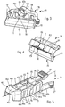
- FIGS. 2 to 9 show an embodiment of the adapter 26 according to the invention as well as the connector 24 intended to cooperate with this adapter, the adapter and the connector together forming a connection system of the wiper blade 12 to the arm 14 or a arm 14 among several types of arms.
- the adapter 24 is generally elongated along the longitudinal axis A, otherwise known as the longitudinal direction. It comprises a body having two lateral walls 42a, 42b for example substantially parallel to each other and to the longitudinal axis A, and at a distance from one another. These walls 42a, 42b are interconnected at their upper ends by an upper transverse wall 44 substantially perpendicular to the side walls 42a, 42b.
- the walls 42a, 42b, 44 here have an elongated shape in the longitudinal direction.
- These side walls 42a and 42b are both delimited by an internal face turned towards a housing 45 and an external face referenced 75.
- This outer face 75 is bordered by a lower longitudinal edge 77 and an upper longitudinal edge 79 opposite the longitudinal edge. lower 77.
- the walls 42a, 42b, 44 of the adapter 26 define between them a longitudinal space, otherwise called housing, 45 in which is intended to be mounted a portion of the connector 24.
- the walls 42a, 42b are here of the double skin type and each comprise two skins, respectively internal and external, parallel and at a distance transverse to one another. The skins are connected together by transverse rectilinear ribs.
- the body of the adapter 26 is connected at a first of its longitudinal ends to a fairing or cowling, also called cap or head 46.
- This head 46 has a lateral dimension greater than that of the body of the adapter and a height also greater than that of the body.
- the lateral walls 42a, 42b of the body of the adapter are thus recessed or offset relative to external lateral faces 46a of the head, and its upper wall 44 is set back or offset with respect to an external upper face 46b of the head.
- the lateral faces 46a of the head 46 are connected to the lateral walls 42a, 42b of the body by lateral rear faces 48a, respectively, which extend substantially perpendicularly to the longitudinal axis A.
- the upper face 46c of the cap 46 is connected at the upper wall 44 of the body by another upper rear face 48b which also extends substantially perpendicular to the longitudinal axis A.
- the rear faces 48a, 48b of the head 46 form bearing faces of the outer end or front of the end piece 28. More precisely, in the mounted position of the adapter in the end piece 28, the free edges before the lateral legs of the end piece are intended to bear on the faces 48a, and the free edge before the transverse wall of the end piece is intended to bear on the face 48b.
- the upper wall 44 of the body of the adapter 26 comprises, substantially in the middle, a window 49.
- the upper wall 44 comprises at its longitudinal end opposite the head 46 longitudinal slots parallel to each other and to the longitudinal axis A and spaced from each other, so as to define between them at least a portion of a longitudinal tongue 50.
- the tongue 50 extends longitudinally on the opposite side to the head 46, in the extension of the upper wall 44. It is elastically deformable and is connected to its outer free end or front to the aforementioned upper push button 27, which projects from the tongue 50. In the free state without constraint, each tongue 50 is such that the push button 27 is located above a plane passing through the upper wall 44.
- the elastic deformations of the tongues here take place in a longitudinal plane median substantially vertical, that is to say substantially perpendicular to the upper wall 44.
- the adapter 26 is thus equipped with an upper push button 27.
- the push button 27 When mounting the adapter 26 in the end piece 28, the push button 27 is intended to engage resiliently snap into the opening 38 to lock the adapter vis-à-vis the end piece.
- the adapter 26 further comprises an upper orifice 51 for engaging a tab of an end piece of arm.
- This orifice 51 is here formed partly in the head 46, at the rear end thereof, and partly in the upper wall 44, at the front end thereof.
- the orifice 51 has a generally square or rectangular shape.
- the lateral walls 42a, 42b of the body extend longitudinally inwardly by longitudinal tabs 52a, 52b that are elastically deformable.
- Each wall 42a, 42b is connected to a tab 52a, 52b, these tabs 52a, 52b being substantially parallel and symmetrical with respect to a median longitudinal plane, substantially vertical, that is to say perpendicular to the upper wall 44 of the 'adapter.
- Each tab 52a, 52b thus carries a push button 27.
- the elastic deformations of the tabs 52a, 52b here take place in a substantially horizontal longitudinal plane, that is to say substantially parallel to the upper wall 44.
- the tabs 52a, 52b can be brought closer to each other by elastic deformation
- the push buttons 27 “are shaped to cooperate with notches of the end piece 28, as will be described in more detail in the following.
- the side walls 42a, 42b each comprise a through orifice 56.
- the orifices 56 of the side walls 42a, 42b are substantially coaxial and here define the axis Y of pivoting of the adapter 24 on the connector 24, and thus of the wiper blade vis-à-vis the arm.
- the orifices 56 are for example circular in section and each comprise a substantially cylindrical inner surface 56a.
- the orifices 56 open at their outer lateral ends on the outer faces 75 of the walls 42a, 42b, respectively, and at their inner lateral ends in the housing 45.
- the internal lateral faces facing the lateral walls 42a, 42b comprise protuberances 60.
- Each lateral wall 42a, 42b comprises a protuberance 60, the protuberances being here facing one another and extending substantially one towards the other. the other.
- the protuberances 60 are symmetrical with respect to a median longitudinal plane of the adapter, perpendicular to the upper wall 44.
- Each protuberance 60 also has a plane of symmetry passing through the pivot axis Y and perpendicular to the long axis.
- Each protuberance 60 is perforated and comprises a through hole. This hole is here formed by one of the aforementioned orifices 56. Each protuberance 60 is thus located on the inner face of the side wall 42a or 42b so as to be traversed by the orifice 56 of this wall.
- Each protuberance 60 has a generally cylindrical shape and here tubular due to the orifice 56 which passes through it.
- the axis of each orifice 56 which coincides with the pivot axis Y, is also coincident with the axis of the corresponding cylindrical protuberance 60, so that the orifice is centered with respect to the protuberance.
- Each protuberance 60 thus forms an annular bead of material around the orifice 56, having substantially a radial thickness relative to the pivot axis Y substantially constant.
- Each protrusion 60 has an axial dimension along the pivot axis Y which represents about 10 to 20% of the axial dimension or width of the housing 45 along the pivot axis Y.
- Each protrusion 60 has an outer diameter which is about 60 to 80% of the height of the corresponding side wall 42a, 42b, measured in a direction substantially perpendicular to the pivot axis Y.
- each protrusion 60 comprises a portion, here below, truncated or chamfered.
- Each truncated or chamfered portion defines a ramp 62 which extends in a plane inclined relative to the side walls 42a, 42b.
- Each ramp 62 defines a sliding surface intended to cooperate with the connector 24.
- the ramps 62 of the protuberances 60 are inclined so that they move away from each other from top to bottom. Their lower ends, located on the side opposite to the upper wall 44, are spaced from each other by a distance L along the pivot axis Y ( figure 6 ).
- each ramp 60 extends at a short distance, along the pivot axis Y, of the inner face of the corresponding side wall 42a, 42b and can be directly connected to this inner face.
- the distance L is substantially equal to the distance between the internal faces of the walls 42a, 42b or the width of the housing 45.
- Each ramp 62 extends over a circumference around the pivot axis Y, representing an angle of between 30 and 150 °, and preferably between 90 and 120 °.
- the side walls 42a, 42b of the body of the adapter 26 further comprise on their outer faces 75 or one of the support means 54, 54a projecting from the outer face 75 which carries them.
- This support means 54, 54a defines bearing faces in the transverse direction, that is to say perpendicularly to the longitudinal direction A passing through the lateral faces 42a and 42b.
- protruding support means 54a are located at the orifices 56, and are traversed by these orifices 56. There is thus a geometrical interference between the external perimeter of the orifice 56 and the support means 54a. .
- the bearing means 54, 54a projecting here comprise strips of material 54, 54a projecting on the outer faces 75 of the side walls 42a, 42b.
- the strips of material have an elongated shape and extend transversely to the longitudinal direction A between the longitudinal edges lower 77 and upper 79 side walls 42a, 42b, the upper longitudinal edge being common to the upper wall 44.
- the strips of material 54, 54a define parallel bearing faces, or substantially parallel, between them. These bearing faces are also here parallel, or substantially parallel, to the outer faces 75 of the side walls 42a, 42b. A plane passing through the bearing face of one or more strips of materials is thus parallel to a plane passing through the outer face 75. A line passing through these bearing faces is also parallel, or substantially parallel, to the longitudinal axis A of the adapter 26.
- each side wall comprises four of said strips of material 54, 54a.
- the strips of material of one of the side walls are symmetrical with respect to the strips of material of the other of the side walls, with respect to a median longitudinal plane of the adapter substantially perpendicular to its upper wall 44.
- the strips of material 54, 54a have substantially all the same thickness measured along the axis of pivoting Y or dimension in the transverse direction.
- the strips of material 54a traversed by the orifices 56 have a width or dimension in the longitudinal direction, measured along the longitudinal direction A, smaller than that of the other strips of material 54, and for example also smaller than the diameter of said orifices 56.
- the median transverse plane perpendicular to the upper wall 44 of the adapter 26 and passing through the pivot axis Y passes through the material strips 54a substantially in their middle and may for example form a plane of symmetry of these bands.
- the material strips 54a are in particular substantially centered on the pivot axis Y and the orifices 56.
- the adapter 26 described above is advantageously unitary, that is to say constituted by the same synthetic material. It can thus be manufactured during a single molding operation, in particular by injection.
- the adapter 26 is fixed to the connector 24 by means of the protuberances 60 which form means for fixing the adapter to the connector and which can furthermore form means for pivoting the adapter with respect to the connector.
- the fastening means are of the elastic snap-fastening type, the protuberances 60 of the adapter 26 being intended to cooperate by elastic snap-fastening with complementary means of the connector 24.
- the connector 24, better visible to Figures 3 and 4 is arranged to be secured, for example by crimping, the wiper blade 12.
- the connector 24 provides a so-called mechanical connection complete with the wiper blade 12, in that there is no degree of freedom.
- the connector 24 can also provide a function for transporting and dispensing a washing liquid from the windshield of the vehicle.
- the connector 24 comprises a base 70 which extends longitudinally and transversely.
- This base 70 comprises a securing zone 72 on the wiper blade 12, and more particularly on at least one vertebra 74 of this wiper blade.
- This securing zone 72 takes for example the form of a groove formed in the base 70, this groove being bordered by two hooks adapted to engage on the wiper blade.
- the wiper blade 12 comprises two parallel and coplanar vertebrae 74 which are spaced from each other to define a housing space of the wiper blade 18 or the body 16 of the wiper blade. wiping.
- Each vertebra comprises a longitudinal edge, opposite the blade 18, which is received in the groove of the connector 24.
- the base 70 is surmounted by a flank 76, for example, made of material with the base.
- This flank 76 has a transverse dimension less than that of the base and a longitudinal dimension substantially equal to that of the base.
- the flank 76 is for example centered on the base 70, along the pivot axis Y.
- the flank 4 may have a plurality of ribs 78 which provide a mechanical reinforcement of the sidewall.
- the connector 24 and the adapter 26 are mechanically connected by a pivot connection.
- this pivot connection is implemented by a cavity 80 made in the sidewall 76.
- This cavity 80 extends along the pivot axis Y and has a circular section. It traverses the flank 76.
- the cavity 80 has a central axis centered on the pivot axis Y.
- the connector 24 described above is advantageously unitary, that is to say constituted by the same synthetic material. This connector can thus be manufactured during a single molding operation, in particular by injection.
- the adapter 26 is mounted on the connector 24 by elastic snapping of its protuberances 60 in the cavity 80 of the connector.
- the ramps 62 of the protuberances 60 of the adapter 26 cooperate with the connector to facilitate this mounting.
- the connector also comprises means facilitating insertion of the protuberances 60 of the adapter 26 into its cavity 10.
- flank 76 of the connector 24 This is grooves 82 formed in the side faces defining the sidewall 76, and the right of which the cavity 80 ends. It will be understood that each groove 82 and the cavity 80 are in intersection with each other, the groove 82 thus extending from an edge 84 of the sidewall 76 to the hole forming the cavity 80.
- the flank 76 has a thickness E1 less than a thickness E2 of a portion of the flank 76 bordering said groove 82. These thicknesses E1, E2 are measured in a direction parallel to the pivot axis Y.
- this groove 82 is delimited by a bottom 82a and by two slices 82b which connect the bottom 82a to the corresponding side face of the sidewall.
- the bottoms 82a of the grooves 82 are parallel or inclined with respect to each other. In the latter case, they are inclined so that their upper ends, located on the opposite side to the cavity 80, are closer than their lower ends.
- the assembly of the adapter 26 on the connector 24 is made only by a vertical translation along an axis perpendicular to the upper wall 44 of the adapter.
- the protuberances 60 of the adapter 26 engage in the grooves 82 of the connector and cooperate with their slices 82b to center the adapter on the connector.
- the ramps 62 have guide surfaces that slide cooperatively with the bottoms 82a of the grooves.
- the distance L above is preferably greater than the thickness E1.
- the distance between protuberances 60, measured along the pivot axis Y is less than the width of the cavity 80 and the thickness E2.
- the ramps 62 rest on the bottoms of the grooves and the downward translation of the adapter is continued so that the side walls 42a, 42 of the adapter are constrained. to deform by moving away from each other due to the slippage of the ramps on the bottoms of the grooves. This operation is continued until the protuberances 60 engage snap or elastic return into the cavity 80 of the connector.
- the adapter is then attached to the connector and may further pivoted about it about the pivot axis Y, by cooperation of its protuberances with the inner cylindrical surface 80a of the cavity.
- the cavity 80 has an internal diameter substantially equal to or slightly greater than that of the protuberances 60.
- the adapter 26 is of the universal type because it is adapted to be attached to several types of arms, whether end piece arm or without end piece.
- FIGS 10 to 20 show several types of arms that can be equipped with the adapter 26 according to the invention.
- Figures 10 and 11 respectively represent two end pieces 28, 28 'of different drive arms.
- Each end piece 28, 28 comprises two lateral legs 32a, 32b whose upper longitudinal edges are interconnected by an upper transverse wall 34.
- the legs 32a, 32b and the wall 34 delimit between them a housing space of the adapter 26.
- the legs 32a, 32b may comprise at their lower longitudinal edges means 36, such as hooks, retaining the adapter 26 in the aforementioned space.
- the upper wall 34 comprises a through opening 38, 38 'intended to receive the upper push button 27.
- the push button 27 is housed in this opening 38 and can pass through the latter so as to project on the face upper wall 34.
- the mounting of the push button 27 in the opening 38 is by simple engagement or interlocking, preferably by snap elastic.
- the side walls 32a, 32b may each comprise a notch 40 of complementary shape of a lateral push button 27 '.
- the lateral push buttons 27 ' are housed in these notches 40 and can pass through so as to project on the outer faces of the walls 32a, 32b. Mounting the push buttons 27 "in the notches 40 is by simple engagement or interlocking, preferably by snap elastic.
- the end pieces 28, 28 ' are different. They have generally the same shape but differ from each other in particular by size and the shape and size of their openings 38, 38 'or notches 40.
- the end pieces 28, 28 ' have substantially the same external width. Furthermore, the ribs 54 of the outer faces of the side walls of the body of the adapter 26 may be spaced from one wall to the other by a transverse distance substantially equal to the internal width of the crosspiece 28, 28 ', so that the end piece is wedged in transverse direction by cooperation of its legs with the side walls of the body of the adapter.
- the adapter 26 is engaged in the end piece 28, 28 'by first tilting the axis of the adapter vis-à-vis the A of the end piece 28 and then engaging the tab 41 of the end piece in the hole 51 of the adapter. During this engagement, the legs of the end piece begin to slide on the support means 54 of the adapter. In addition, the front end edge of the upper wall of the end piece bears on the face 48b of the head 46 of the adapter. The rear end of the adapter is then brought closer to the end piece until the lateral push buttons 27 'engage by snap elastically in the notches 40 of the end piece 28, 28'. The front end edges of the lateral legs 32a, 32b of the end piece bear against the faces 48a of the head 46 of the adapter. The longitudinal axes of the adapter and the end piece 28 are then substantially parallel.
- This connecting member 88 is mounted on the adapter 26 and covers it integrally in the example shown. It has a longitudinal shape and includes an inner housing in which is mounted and retained the adapter. It comprises at its rear end lateral notches intended to receive by snap elastic push buttons 27 ', respectively.
- Side walls 85, 86 of the member 88 comprise on their inner faces 87, 89 projecting means 100, 100a which define bearing faces in the transverse direction, and which are configured to cooperate with the bearing means projection 54, 54a of the adapter 26.
- the projecting means 100, 100a of the member 88 here comprise strips of material 100, 100a projecting on the inner faces 87 and 89 of the side walls 85, 86 of the member 88.
- the strips of material have an elongated shape and extend longitudinally between the lower and upper longitudinal edges of these walls.
- the strips of material 100, 100a define substantially parallel bearing surfaces. These bearing surfaces here are substantially parallel to the inner faces 87, 89 of the side walls and to the longitudinal axis A of the member 88.
- each side wall comprises three of said strips of material.
- the strips of material of one of the side walls are symmetrical with respect to the strips of material of the other of the side walls, with respect to a median longitudinal plane of the member perpendicular to its upper wall.
- the strips of material have substantially all the same thickness or dimension in the transverse direction, measured along the pivot axis Y.
- the median material strips 100a have a width or dimension in the longitudinal direction, measured along the longitudinal direction A less than that of the other strips of material.
- the outer faces 75 of the side walls 42a of the adapter 26 are spaced apart by a distance H in the transverse direction, that is to say along the pivot axis Y, from the internal faces 89 of the connecting member. 88, due to the mutual cooperation of their material bands 54, 54a, 100, 100a.
- the rod arm 14 ' comprises an end engaged in the connecting member 88, over substantially its entire length, from the rear longitudinal end of the member 88.
- the rod arm 14' is secured to the member 88 by means appropriate and can be removed from the body by the actuation of push buttons 92 carried by the member and intended to cooperate with the end of the rod arm 14 '.
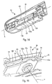
- the figure 16 shows a second connecting member 94 which can be used to connect the adapter 26 to two other types of arms, respectively shown in FIGS. Figures 17 and 18 .
- the connecting member 94 is similar to the adapter and is intended to be mounted on the adapter to cover it at least in part. It is used in particular to be able to equip a 14 "arm with a terminal piece 28" wide with the adapter 26.
- the end piece 28 "of the arm 14" of the figure 17 differs from those Figures 10 and 11 in particular in that it has a larger width.
- the connecting member 94 is configured to make up the clearances between the adapter 26 and the end piece 28 ", and to match the shapes of the latter by being sandwiched between them.
- the end piece 28" is similar to those of the Figures 10 and 11 .
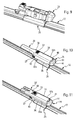
- the arm 14 "'of the figure 18 is a lateral locking arm (English side-lock) whose end piece 28 '' comprises firstly a cylindrical pin 96 extending transversely on one side of the end piece, and a latch 98 in L-shape which extends transversely on the same side as the pin 96, and parallel and at a distance from the latter.
- the pin 96 is intended to pass through the lateral orifices of the member 94, which are aligned on the pivot axis Y and thus aligned with the orifices 56 of the adapter 26 and the cavity 80 of the connector 24.
- the pin 96 is engaged in these orifices and cavities until its transverse part 28 '"bears on an external lateral face 99a of the member 94
- the transverse part 28 '" can slide cooperatively with the external lateral face 99a during the pivoting of the wiper blade with respect to the arm 14"'.
- the latch 98 in L comprises a hook at its free end which is intended to cooperate by sliding with an opposite side face 99b of the member 94 during the pivoting of the wiper blade vis-à-vis the arm 14 "', and prevents accidental disconnection of the wiper blade from the operating arm.
- the 14 "arm Figures 19 and 20 is another lateral locking arm whose end piece 28 '"also comprises a cylindrical pin 96 extending transversely on one side of the end piece, as well as an L-shaped lock 98 which extends transversely on the same side than the pin 96, and parallel and at a distance from the latter.
- the arm 14 "" here cooperates directly with the adapter 26 according to the invention without interposition of a part.
- the pin 96 is intended to pass through the orifices 56 of the adapter 26 and the cavity 80 of the connector.
- the pin 96 is engaged in these orifices and the cavity until its transverse part 28 "" bears on the bearing face of one of the material strips 54a traversed by the orifice 56.
- the crosspiece 28 "" can cooperate by sliding with this bearing face during pivoting of the wiper blade vis-à-vis the arm.
- the L-shaped latch 98 comprises a hook at its free end which is intended to cooperate by sliding with the bearing face of one of the material strips 54 on the other side of the adapter 26, and prevents accidental disconnection. wiper blade vis-à-vis the operating arm.
- the material strips 54, 54a on which the arm 14 "" is supported and can slide in operation are respectively located on both sides of the adapter 26. The strips of material 54, 54a and allow to catch the transverse clearances of the prior art, between the adapter and the end piece of the arm 14 "".
- the adapter 26 "universal" according to the invention can thus be associated with several types of drive arm.
Landscapes
- Engineering & Computer Science (AREA)
- Mechanical Engineering (AREA)
- Physics & Mathematics (AREA)
- Fluid Mechanics (AREA)
- Quality & Reliability (AREA)
- Cleaning Implements For Floors, Carpets, Furniture, Walls, And The Like (AREA)
- Connector Housings Or Holding Contact Members (AREA)
- Pivots And Pivotal Connections (AREA)
- Ink Jet (AREA)
Applications Claiming Priority (1)
| Application Number | Priority Date | Filing Date | Title |
|---|---|---|---|
| FR1556028A FR3037902B1 (fr) | 2015-06-29 | 2015-06-29 | Adaptateur pour relier un balai d'essuyage a un bras d'entrainement |
Publications (1)
| Publication Number | Publication Date |
|---|---|
| EP3112224A1 true EP3112224A1 (de) | 2017-01-04 |
Family
ID=54608647
Family Applications (1)
| Application Number | Title | Priority Date | Filing Date |
|---|---|---|---|
| EP16176399.0A Withdrawn EP3112224A1 (de) | 2015-06-29 | 2016-06-27 | Adapter zum verbinden eines scheibenwischers mit einem antriebsarm |
Country Status (4)
| Country | Link |
|---|---|
| US (1) | US10369971B2 (de) |
| EP (1) | EP3112224A1 (de) |
| CN (1) | CN106335472B (de) |
| FR (1) | FR3037902B1 (de) |
Cited By (1)
| Publication number | Priority date | Publication date | Assignee | Title |
|---|---|---|---|---|
| FR3084315A1 (fr) * | 2018-07-27 | 2020-01-31 | Valeo Systemes D'essuyage | Adaptateur constitutif d'un systeme d'essuyage |
Families Citing this family (2)
| Publication number | Priority date | Publication date | Assignee | Title |
|---|---|---|---|---|
| USD842213S1 (en) * | 2016-01-26 | 2019-03-05 | Cap Corporation | Adapter of windscreen wiper |
| BR112020016882A2 (pt) * | 2018-02-19 | 2020-12-15 | Trico Products Corporation | Adaptador, acoplador e montagem de braço de limpador de para-brisa |
Citations (4)
| Publication number | Priority date | Publication date | Assignee | Title |
|---|---|---|---|---|
| DE102005019389A1 (de) * | 2005-04-28 | 2006-11-02 | Robert Bosch Gmbh | Wischblatt |
| US20120060316A1 (en) * | 2010-09-15 | 2012-03-15 | Valentin Avasiloaie | Universal coupler for a beam blade windshield wiper assembly |
| DE102012209956A1 (de) * | 2012-06-14 | 2013-12-19 | Robert Bosch Gmbh | Wischblattadaptersystem |
| US20140338143A1 (en) * | 2011-07-27 | 2014-11-20 | Valeo Systèmes d'Essuyage | Windscreen wiper adapter with safety position |
Family Cites Families (7)
| Publication number | Priority date | Publication date | Assignee | Title |
|---|---|---|---|---|
| DE10257988A1 (de) * | 2002-04-04 | 2004-02-05 | Robert Bosch Gmbh | Wischhebel mit einem Wischerarm und einem an diesem angelenkten Wischblatt |
| IT217072Z2 (it) * | 1989-05-23 | 1991-10-29 | Fister Spa | Dispositivo tergicristallo per un autoveicolo provvisto di mezzi di collegamento della spazzola al braccio di tipo perfezionato |
| WO2002034594A1 (de) * | 2000-10-28 | 2002-05-02 | Robert Bosch Gmbh | Vorrichtung zum verbinden eines wischerarms mit einem wischblatt, sowie ein wischblatt beziehungsweise ein wischerarm |
| DE102011001687A1 (de) * | 2011-03-31 | 2012-10-04 | Valeo Systèmes d'Essuyage | Wischblatt zum Reinigen von Fahrzeugscheiben sowie Wischarm |
| DE102011079470A1 (de) * | 2011-07-20 | 2013-01-24 | Robert Bosch Gmbh | Wischblattadaptersystem |
| DE102011089922A1 (de) * | 2011-12-27 | 2013-06-27 | Robert Bosch Gmbh | Wischblattvorrichtung |
| KR101350277B1 (ko) * | 2012-01-27 | 2014-01-14 | 케이씨더블류 주식회사 | 플랫 와이퍼 블레이드 및 플랫 와이퍼 블레이드 조립체 |
-
2015
- 2015-06-29 FR FR1556028A patent/FR3037902B1/fr active Active
-
2016
- 2016-06-27 EP EP16176399.0A patent/EP3112224A1/de not_active Withdrawn
- 2016-06-28 US US15/195,163 patent/US10369971B2/en active Active
- 2016-06-29 CN CN201610808651.2A patent/CN106335472B/zh active Active
Patent Citations (4)
| Publication number | Priority date | Publication date | Assignee | Title |
|---|---|---|---|---|
| DE102005019389A1 (de) * | 2005-04-28 | 2006-11-02 | Robert Bosch Gmbh | Wischblatt |
| US20120060316A1 (en) * | 2010-09-15 | 2012-03-15 | Valentin Avasiloaie | Universal coupler for a beam blade windshield wiper assembly |
| US20140338143A1 (en) * | 2011-07-27 | 2014-11-20 | Valeo Systèmes d'Essuyage | Windscreen wiper adapter with safety position |
| DE102012209956A1 (de) * | 2012-06-14 | 2013-12-19 | Robert Bosch Gmbh | Wischblattadaptersystem |
Cited By (1)
| Publication number | Priority date | Publication date | Assignee | Title |
|---|---|---|---|---|
| FR3084315A1 (fr) * | 2018-07-27 | 2020-01-31 | Valeo Systemes D'essuyage | Adaptateur constitutif d'un systeme d'essuyage |
Also Published As
| Publication number | Publication date |
|---|---|
| FR3037902B1 (fr) | 2019-05-10 |
| US10369971B2 (en) | 2019-08-06 |
| US20160375873A1 (en) | 2016-12-29 |
| FR3037902A1 (fr) | 2016-12-30 |
| CN106335472B (zh) | 2020-03-24 |
| CN106335472A (zh) | 2017-01-18 |
Similar Documents
| Publication | Publication Date | Title |
|---|---|---|
| EP3118070B1 (de) | Organ für ein verbindungssystem eines wischerblatts | |
| EP1590214B1 (de) | Einen wischerarm mit einem wischblatt verbindender verbinder | |
| EP3168092B1 (de) | Organ für ein verbindungssystem eines wischerblatts an einen scheibenwischerarm | |
| EP3473503B1 (de) | Adapter für einen scheibenwischer eines kraftfahrzeugs, und scheibenwischer, der einen solchen adapter umfasst | |
| FR2879986A1 (fr) | Balai d'essuie-glace plat universel et connecteur amovible associe | |
| FR3056510A1 (fr) | Adaptateur pour la connexion d'un balai d'essuyage a un bras d'entrainement d'un systeme d'essuyage pour vehicule automobile | |
| EP3168093B1 (de) | Adapter für ein kraftfahrzeugwischerblatt | |
| EP2755874B1 (de) | Verbindungsanordnung für eine scheibenwischanlage eines kraftfahrzeugs | |
| EP3112227B1 (de) | Adapter zum verbinden eines scheibenwischers mit einem antriebsarm | |
| EP3112223B1 (de) | Organ für ein verbindungssystem eines wischerblatts an mehrere scheibenwischerarme | |
| FR3072629A1 (fr) | Adaptateur pour un essuie-glace de vehicule automobile et ensemble comportant un tel adaptateur | |
| FR3043040A1 (fr) | Adaptateur pour un essuie-glace de vehicule automobile | |
| EP3112224A1 (de) | Adapter zum verbinden eines scheibenwischers mit einem antriebsarm | |
| EP3251905B1 (de) | Anschlussadapter des freien endabschnitts eines scheibenwischerarms, und anordnung, die einen solchen adapter und einen scheibenwischerarm umfasst | |
| WO2016005103A1 (fr) | Adaptateur de liaison d'un balai d'essuie-glace à un bras d'entraînement de ce balai | |
| EP3165417B1 (de) | Adapter für ein kraftfahrzeugwischerblatt | |
| EP3112225A1 (de) | Organ für ein verbindungssystem eines wischerblatts an mehrere scheibenwischerarme | |
| EP3112226B1 (de) | Organ für ein verbindungssystem eines wischerblatts an einen scheibenwischerarm | |
| FR3051751A1 (fr) | Adaptateur de raccordement de l’extremite libre d’un bras d’essuie-glace, ensemble comportant un tel adaptateur et un bras d’essuie-glace | |
| EP3112228B1 (de) | Organ für ein verbindungssystem eines wischerblatts an einen scheibenwischerarm | |
| FR3043043A1 (fr) | Adaptateur pour balai d’essuyage de vitre, et dispositif de raccordement correspondant entre un balai et un bras d’entrainement | |
| FR3091226A1 (fr) | Adaptateur pour balai d’essuie-glace de véhicule automobile | |
| EP3248848B1 (de) | Befestigungsvorrichtung für die montage eines scheibenwischerblatts auf einem scheibenwischerarm, und entsprechendes scheibenwischsystem | |
| EP4124521A1 (de) | Verbindungsvorrichtung zwischen wischblatt und antriebsarm | |
| FR3043614A1 (fr) | Adaptateur pour un essuie-glace de vehicule automobile |
Legal Events
| Date | Code | Title | Description |
|---|---|---|---|
| PUAI | Public reference made under article 153(3) epc to a published international application that has entered the european phase |
Free format text: ORIGINAL CODE: 0009012 |
|
| 17P | Request for examination filed |
Effective date: 20160627 |
|
| AK | Designated contracting states |
Kind code of ref document: A1 Designated state(s): AL AT BE BG CH CY CZ DE DK EE ES FI FR GB GR HR HU IE IS IT LI LT LU LV MC MK MT NL NO PL PT RO RS SE SI SK SM TR |
|
| AX | Request for extension of the european patent |
Extension state: BA ME |
|
| 17Q | First examination report despatched |
Effective date: 20180604 |
|
| GRAP | Despatch of communication of intention to grant a patent |
Free format text: ORIGINAL CODE: EPIDOSNIGR1 |
|
| INTG | Intention to grant announced |
Effective date: 20190718 |
|
| STAA | Information on the status of an ep patent application or granted ep patent |
Free format text: STATUS: THE APPLICATION IS DEEMED TO BE WITHDRAWN |
|
| 18D | Application deemed to be withdrawn |
Effective date: 20191129 |