EP3375675B1 - Abdeckung, verbindungsvorrichtung für die montage eines scheibenwischerblatts auf einem entsprechenden scheibenwischerarm, und entsprechendes scheibenwischsystem - Google Patents
Abdeckung, verbindungsvorrichtung für die montage eines scheibenwischerblatts auf einem entsprechenden scheibenwischerarm, und entsprechendes scheibenwischsystem Download PDFInfo
- Publication number
- EP3375675B1 EP3375675B1 EP18161105.4A EP18161105A EP3375675B1 EP 3375675 B1 EP3375675 B1 EP 3375675B1 EP 18161105 A EP18161105 A EP 18161105A EP 3375675 B1 EP3375675 B1 EP 3375675B1
- Authority
- EP
- European Patent Office
- Prior art keywords
- cap
- cover
- wiper arm
- windscreen wiper
- terminal segment
- Prior art date
- Legal status (The legal status is an assumption and is not a legal conclusion. Google has not performed a legal analysis and makes no representation as to the accuracy of the status listed.)
- Active
Links
Images


Classifications
-
- B—PERFORMING OPERATIONS; TRANSPORTING
- B60—VEHICLES IN GENERAL
- B60S—SERVICING, CLEANING, REPAIRING, SUPPORTING, LIFTING, OR MANOEUVRING OF VEHICLES, NOT OTHERWISE PROVIDED FOR
- B60S1/00—Cleaning of vehicles
- B60S1/02—Cleaning windscreens, windows or optical devices
- B60S1/04—Wipers or the like, e.g. scrapers
- B60S1/32—Wipers or the like, e.g. scrapers characterised by constructional features of wiper blade arms or blades
- B60S1/40—Connections between blades and arms
- B60S1/4067—Connections between blades and arms for arms provided with a side pin
- B60S1/4077—Connections between blades and arms for arms provided with a side pin characterised by the connecting part of, or an intermediate element mounted on, the wiper blade
-
- B—PERFORMING OPERATIONS; TRANSPORTING
- B60—VEHICLES IN GENERAL
- B60S—SERVICING, CLEANING, REPAIRING, SUPPORTING, LIFTING, OR MANOEUVRING OF VEHICLES, NOT OTHERWISE PROVIDED FOR
- B60S1/00—Cleaning of vehicles
- B60S1/02—Cleaning windscreens, windows or optical devices
- B60S1/04—Wipers or the like, e.g. scrapers
- B60S1/32—Wipers or the like, e.g. scrapers characterised by constructional features of wiper blade arms or blades
- B60S1/40—Connections between blades and arms
- B60S1/4067—Connections between blades and arms for arms provided with a side pin
- B60S1/407—Connections between blades and arms for arms provided with a side pin with means provided on the arm for locking the side pin
-
- B—PERFORMING OPERATIONS; TRANSPORTING
- B60—VEHICLES IN GENERAL
- B60S—SERVICING, CLEANING, REPAIRING, SUPPORTING, LIFTING, OR MANOEUVRING OF VEHICLES, NOT OTHERWISE PROVIDED FOR
- B60S1/00—Cleaning of vehicles
- B60S1/02—Cleaning windscreens, windows or optical devices
- B60S1/04—Wipers or the like, e.g. scrapers
- B60S1/32—Wipers or the like, e.g. scrapers characterised by constructional features of wiper blade arms or blades
- B60S1/40—Connections between blades and arms
- B60S1/4006—Connections between blades and arms for arms provided with a hook-shaped end
- B60S1/4009—Connections between blades and arms for arms provided with a hook-shaped end comprising a detachable intermediate element mounted on the hook-shaped end
- B60S1/4016—Connections between blades and arms for arms provided with a hook-shaped end comprising a detachable intermediate element mounted on the hook-shaped end the element being provided with retention means co-operating with the hook-shaped end of the arm
- B60S1/4019—Connections between blades and arms for arms provided with a hook-shaped end comprising a detachable intermediate element mounted on the hook-shaped end the element being provided with retention means co-operating with the hook-shaped end of the arm the retention means being protrusions or holes
Definitions
- the present invention relates to the fixing of a wiper blade on a wiper arm, in particular of a motor vehicle. It relates more particularly to a cover covering the connection between the arm and the wiper blade.
- the present invention also relates to a connection device for assembling the wiper blade to the wiper arm of a motor vehicle comprising such a cover.
- the invention also relates to a corresponding wiping system.
- a motor vehicle is fitted with wipers for cleaning a glazed surface such as the windshield.
- wipers generally comprise wiper arms, performing an angular reciprocating movement, and blades, themselves carrying scraper blades. These blades rub against the glass surface to evacuate cleaning liquid by bringing it outside the driver's field of vision.
- the blade is attached to the wiper arm by a connection device.
- the invention relates more particularly to a connection device for a wiper arm of the so-called lateral pivot or lateral pivot axis type, also known under the name "side lock" in English.
- a wiper arm has a terminal segment, configured to cooperate with the connector.
- This terminal segment comprises a first elongated element or longitudinal end extending substantially in the extension of the wiper arm.
- a substantially cylindrical rod extends perpendicularly from the longitudinal end of the wiper arm and forms a transverse axis.
- the connection device comprises a connector and a cover.
- the connector is a part intended to be secured to the wiper blade.
- the connector is also intended to be crossed by the transverse axis carried by the wiper arm, in order to link the connector to the end segment of the wiper arm by a pivot connection around the transverse axis.
- the wiper blade can pivot around the transverse axis, to adapt to the glass surface during the back and forth movement of the wiper.
- the cover is intended to be assembled and locked on the connector.
- connection device comprises means allowing the connection and the locking of the cover on the connector mounted on the wiper blade.
- DE 102.59.480 discloses a cover according to the preamble of claim 1.
- One of the aims of the present invention is to at least partially overcome these problems of the prior art by proposing a lower-cost alternative facilitating the mounting and dismounting of the cover on the connector intended to be connected to the wiper blade. window on the one hand and the wiper arm on the other hand via the transverse axis.
- the lower part of the cover comprises at least one holding means made in one piece with the cover and configured to cooperate with the end segment of the wiper arm for assembling the cover to the end segment. of the wiper arm.
- Such a cover is simple to produce.
- a movement in the tool is sufficient to produce the holding means integrally formed with the cover.
- the invention also relates to a motor vehicle wiping system comprising a connection device as defined above.
- the motor vehicle wiping system comprises at least one wiper blade.
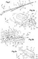
- the wiping system 1 may or may not include the wiper arm 5.
- the wiper blade 3 extends longitudinally in a direction X.
- the wiper blade 3 comprises in particular a deflector 31 (or “spoiler” in English) and a wiping blade 33.
- the deflector 31 and the wiping blade 33 are made of flexible material.
- the wiper arm 5 extends longitudinally in a direction L.
- the wiper arm 5 has a terminal segment 9, better visible on the Figures 2a, 2b , configured to be connected to wiper blade 3. More specifically, the terminal segment 9 of the wiper arm 5 can be connected to the wiper blade 3 via the connection device 7.
- the terminal segment 9 has a longitudinal end 11.
- the longitudinal end 11 carries a transverse axis 13 configured to define a pivot axis of the wiper blade 3 (not visible on the Figures 2a, 2b ).
- the wiper arm 5 is said to have a lateral pivot or “side lock” in English.
- the transverse axis 13 is of generally substantially cylindrical shape. In other words, the transverse axis 13 is generally cylindrical or similar. This transverse axis 13 extends in the transverse direction T, perpendicular to the longitudinal direction L.
- connection device 7 allows the mounting and articulation of the wiper blade 3, also referring to the figure 1 , on the wiper arm 5, more precisely on the longitudinal end 11.
- the connection device 7 comprises for this purpose a connector 15 and a cover 17.
- Connector 15 ( Figures 2a to 2c ) is configured to be connected to the wiper blade 3 on the one hand and to the wiper arm 5 on the other hand ( figure 1 ).
- the connector 15 serves as an interface with the wiper blade 3 and the wiper arm 5.
- the cover 17 is configured to cooperate with the connector 15 so as to fix the wiper blade 3 to the wiper arm 5.
- the cover 17 allows in particular the locking of the assembly.
- the transverse axis 13 (visible on the Figures 2a, 2b ) is mounted in the connector 15 and held by the cover 17.
- the connector 15 and the cover 17 therefore cooperate to hold and fix the wiper blade 3 on the wiper arm 5.
- a connection device 7 can comprise different types of connectors 15 and covers 17. The differences between several embodiments of the connector 15 and of the cover 17 are explained below.
- connection device 7 is configured to cooperate with a transverse axis 13 of the wiping arm.
- the transverse axis comprises for example a shoulder 131 visible on the figure 2d . Therefore, the transverse axis 13 has a first section 133 of first diameter and a second section 135 of second diameter, for example less than the first diameter.
- the first section 133 is configured to be assembled to the connector 15 (not visible on the figure 2d ), and the second section 135 is configured to be assembled at the longitudinal end 11 of the wiper arm 5 (not visible on the figure 2d ).
- the shoulder 131 thus serves as a bearing surface at the longitudinal end 11 of the wiper arm 5 in the assembled state of the transverse axis 13 and the longitudinal end 11 (see figure 2e ).
- the transverse axis 13 may further include an end 137 of diameter greater than the second section 135.
- the end 137 may be formed after assembly of the transverse axis 13, more precisely of the second section 135, to the wiper arm ice 5 (see also Figures 2a, 2b , 2nd ), for example by bolting, so as to secure the longitudinal end 11 and the transverse axis 13.
- the second section 135 is interposed between the first section 133 and the end 137 (see figure 2d ).
- the shape of the transverse axis 13, in particular of the second section 135, is complementary to the shape of an orifice (not visible) formed on the longitudinal end 11 of the terminal segment 9 of the wiper arm 5 (see Figures 2a and 2b ).
- connector 15 configured to be connected to the cover 17 but also to the wiper arm 5, and to the wiper blade 3, not visible on the Figures 2a to 2c .
- the connector 15 is for example directly connected to the wiper arm 5. Likewise, the connector 15 can be directly fixed to the wiper blade 3.
- the connector 15 has for example a form of longitudinal main extension.
- the connector 15 can be symmetrical with respect to a plane, called the median plane, in the transverse T and vertical V directions and passing through the center of the connector 15.
- the symmetrical connector 15 can be assembled in any direction on the brush wiper 3.
- the connector 15 has a first part 151 or part for connection to the wiper blade 3, configured to be connected to the wiper blade 3 (not visible on the Figures 2a to 2c ) and a second part 153 opposite or connecting part to the wiper arm 5 configured to cooperate with the transverse axis 13 of the end segment 9 of the wiper arm 5.
- the first part 151 of the connector 15 has for example a shape of an elongated stirrup in the longitudinal direction L and intended to enclose the wiper blade 3, not shown in the Figures 2a to 2c .
- the first part 151 of the connector 15 has a channel 155 for holding the wiper blade 3 (not visible on the Figures 2a to 2c ).
- the shape of the retaining channel 155 is for example adapted to the shape of the deflector 31 of the wiper blade 3 (see figure 1 ).
- the second part 153 of the connector 15 comprises, in this example illustrated on the Figures 2a, 2b , two side walls 157 or side flanges.
- the side walls 157 are arranged opposite and here extend along a plane parallel to the plane L, V.
- the side walls 157 have means of assembly to the transverse axis 13.
- an orifice 159 for the passage of the transverse axis 13 is formed in each side wall 157.
- the orifices 159 form the means d assembly to the transverse axis 13.
- the orifices 159 are of shape complementary to the shape of the transverse axis 13, in particular of the first section 133.
- the orifices 159 are of circular section according to the example illustrated.
- connection device 7 The flanges or side walls 157 are received in the internal space delimited by the cover 17 in the assembled state of the connection device 7 (see Figures 2a to 2c ).
- the cover 17 is intended to be fixed on the connector 15 on the side opposite to the wiper blade 33 of the wiper blade 3, also referring to the figure 1 .
- the cover 17 can be mounted on the end segment 9 of the wiper arm 5, the transverse axis 13 of which is mounted in the connector 15.
- the cover 17 has a longitudinal shape.
- the longitudinal direction L of the trihedron corresponds to the main direction of the cover 17.
- the cover 17 is configured to be assembled to the terminal segment 9 of the wiper arm 5 by translation in a direction perpendicular to the longitudinal direction of the cover 17 and also perpendicular to the transverse axis 13.
- the cover 17 is configured to be assembled to the terminal segment 9 of the wiper arm 5 by translation in the vertical direction V.
- cover 17 has for example an open shape, that is to say one which is not closed on all sides.
- the cover 17 comprises an upper part 171 and an opposite lower part 173.
- the upper part 171 is configured to cover the end segment 9 of the wiper arm 5 carrying the transverse axis 13 in the assembled state of the cover 17 to the wiper arm 5 (see figures 2c and 2nd ).
- the upper part is for example formed by an upper wall 171 of the cover 17, which can be of substantially rectangular shape, that is to say of rectangular shape or equivalent or similar.
- the cover 17 also includes two opposite side walls 175 connected by the upper wall 171.
- the side walls 175 extend from the upper wall 171.
- the side walls 175 extend in the direction of the terminal segment 9 of the wiper arm 5.
- the cover 17 also comprises according to the first illustrated embodiment, an end wall 177 connected to the upper wall 171 and to the side walls 175.
- the end wall 177 here extends along a plane parallel to the plane V
- T and the side walls 175 here extend along a plane parallel to the plane L, V.
- lower part 173 means both a lower wall arranged opposite the upper part here of the upper wall 171, and one or more lower edges of the cover 17, in particular side walls 175 and / or end 177 of the cover 17.
- the lower part 173 may comprise a portion of the side walls 175 and / or of the end 177 of the cover 17 which is on the side opposite to the upper wall 171.
- no wall is arranged opposite the upper wall 171.
- the lower part 173 is formed by the lower edges as well as the lower portions of the side walls 175 and possibly of the end wall 177.
- the lower part 173 of the cover 17 comprises at least one holding means 19 produced in one piece with the cover 17.
- FIG. 19 An example of holding means 19 according to the first embodiment is shown in the figures 2b , 2nd, 2f, 2g .
- or the holding means 19 are configured to cooperate with the terminal segment 9 of the wiper arm 5 for assembling the cover 17 to the terminal segment 9 of the wiper arm 5.
- “Holding” means means any element, or device or member participating in maintaining the terminal segment 9 of the wiper arm 5 in the cover 17, in the assembled state. Mention may be made, by way of nonlimiting example, and in a non-exhaustive manner, of one or more reliefs, hooks, one or more protuberances, tongues, lugs, ribs or any other deformation of the cover 17.
- two holding means 19 are provided on the lower part 173 of the cover 17. These holding means 19 may comprise at least one latching element or member.
- Each holding means 19 may include at least one relief 21.
- the or each relief 21 is formed on the lower part 173 of the cover 17, namely in this example formed on the lower portion of a side wall 175 of the cover 17.
- the or each relief 21 came integrally with the cover 17.
- the cover 17 may include at least two distinct reliefs 21.
- the two reliefs 21 are advantageously arranged on the same side wall 175.
- a single relief 21 or on the contrary more than two reliefs 21 can be envisaged.
- Each relief 21 projects into the side wall 175, more precisely on the lower portion or the bottom of the side wall 175, extending from the side wall 175 towards the inside of the cover 17.
- the or each relief 21 extends longitudinally in the longitudinal direction L of the cover 17.
- snap-on reliefs 21 configured to block the withdrawal of the terminal segment 9 of the wiper arm 5 after assembly with the cover 17.
- These snap-on reliefs 21 are advantageously also shaped so to facilitate the assembly of the terminal segment 9 of the wiper arm 5 with the cover 17.
- each relief 21 has an oblique face 211 and a stop face 213.
- the oblique face 211 is oblique or inclined relative to the lower part 173 of the cover 17.
- the oblique face 211 is inclined relative to the plane formed by the side wall 175 carrying the relief 21. This is here 'a plane parallel to the plane L, T.
- the oblique face 211 is configured to be in contact with the terminal segment 9 of the wiper arm 5 during assembly of the terminal segment 9 with the cover 17. More precisely, the oblique face 211 is the first face of each relief 21 to be in contact with the longitudinal end 11 of the terminal segment 9 of the wiper arm 5. This oblique face 211 acts as a leading edge.
- This oblique face 211 is configured so as to facilitate the introduction of the wiper arm 5, that is to say the sliding movement or vertical translation. To do this, provision is made, for example, for the oblique face 211 to form an ascending slope in the direction of introduction of the terminal segment 9 of the wiper arm 5 into the cover 17.
- the stop face 213, better visible on the figure 2f forms a rim against which the terminal segment 9 of the wiper arm 5 is configured to come into support after assembly.
- the stop face 213 may be substantially flat. In other words, the stop face 213 is flat or of equivalent shape.
- each relief 21 is produced in the form of a polyhedron comprising the oblique face 211, the stop face 213, and further comprising a base, and two opposite lateral faces 215.
- the base of the relief 21 coincides with the internal face of the side wall 175 of the cover 17 carrying the relief 21.
- the term “internal face” of a side wall 175 of the cover 17 is understood to mean the face arranged on the side of the connector 15 and being opposite a lateral face 157 of the connector 15 in the assembled state of the connection device 7.
- This base of the relief 21 delimits in the example illustrated a substantially rectangular shape extending longitudinally in the direction L.
- the base of the relief 21 may be of rectangular shape or the like.
- the lateral faces 215 of the relief 21 are respectively of substantially triangular shape.
- the side faces 215 are of triangular or similar shape. These lateral faces 215 join the base, the stop face 213 and the oblique face 211.
- the latching relief or reliefs 21 may have a function of guiding the terminal segment 9 of the wiper arm 5, during the assembly of the terminal segment 9 in the cover 17.
- the cover 17 to further comprise a guide for the end 137 of the transverse axis 13 during the introduction of the terminal segment 9 of the wiper arm 5 into the cover 17.
- This guide is for example made in the form of a recess 22 on the side wall 175 having the reliefs 21.
- This recess 22 is visible on the figures 2b , 2nd and 2g .
- the recess 22 is located between the two reliefs 21.
- the recess 22 is of a shape suitable for guiding the end 137 according to a vertical sliding movement, and is therefore complementary to the shape of the end 137.
- the recess 22 has for example a substantially "U” shape , as can be seen on the figure 2b . In other words, the recess 22 has a "U" shape or an equivalent shape approaching the "U" shape.
- the base of the "U” is in this example near the upper wall 171 of the cover 17 and the ends of the branches of the "U" on either side of the base are located near the reliefs 21.
- the cover 17 allows in particular the locking of the assembly.
- the cover 17 includes at least one fixing means 23 (see figures 2e, 2g, 2h ) configured to cooperate with the transverse axis 13, so as to fix and maintain in position, the transverse axis 13 to the cover 17 in the assembled state of the cover 17 to the terminal segment 9.
- the fixing means 23 can allow the fixing / the maintenance of the transverse axis by form cooperation with the transverse axis 13.
- the fixing means 23 comprises at least one orifice 25 formed on the cover 17 and configured to block the transverse axis 13 carried by the wiper arm 5 in the assembled state of the cover 17 to the terminal segment 9. According to the first embodiment, it is a blind hole 25.
- the orifice 25 is provided on the side wall 175 of the cover 17 opposite to the side wall 175 carrying the holding means 19. This orifice 25 is therefore arranged on the side opposite to the two reliefs 21 previously described.
- fastening means 23 can also have a slope 26.
- the slope 26 is formed on the internal face of the side wall 175 of the cover 17 having the orifice 25.
- This slope 26 is arranged so as to start from the lower edge of the side wall 175 of the cover 17 having the orifice 25, to end by forming a portion of the contour of the orifice 25.
- the slope 26 is inclined relative to the general plane defined by the side wall 175 of the cover 17 having the orifice 25.
- the slope 26 is inclined relative to the plane defined by this side wall 175 of an angle ⁇ of the order of 10 ° to 30 °.
- the angle ⁇ can be in a nonlimiting manner of the order of 15 °.
- the slope 26 is ascending from the bottom edge from the side wall 175 to the orifice 25.
- the fixing means 23 may further comprise at least two protrusions 27 formed on the upper part 171 of the cover 17. More specifically, the protrusions 27 are formed on the internal face of the upper wall 171 forming the upper part.
- the term “internal face” means the face of the upper wall 171 intended to be arranged opposite the connector 15 in the assembled state of the connection device 7.
- the transverse axis 13 of the terminal segment 9 of the wiper arm 5 is configured to engage between the two protrusions 27 during assembly with the cover. 17, as is better visible on the figure 2e . This allows the centering of the terminal segment 9 of the wiper arm 5 and also contributes to maintaining the transverse axis 13 in position.
- the protrusions 27 each have, substantially an eight shape, subsequently simplified by an “8” shape using the reference numeric "8".
- the protuberances have an “8” or equivalent shape, that is to say that approximates the “8” shape.
- this "8" shape is not limiting and any other shape can be considered.
- the wiper arm 5 fixed to the connector 15 and to the cover 17 by the transverse axis 13 is therefore kept torn off in the vertical direction V by the cover 17 and in particular the reliefs 21 and the blind hole 25, and possibly the protrusions 27, preventing it from coming out from below with reference to the arrangement of the elements on the Figures 1, 2a, 2c and 2 F .
- the cover 17 comprises at least one flexible or flexible element.
- at least the side wall 175 of the cover 17 carrying the relief 21 is at least partially flexible and is therefore configured to be deformed so as to allow locking or unlocking.
- the two opposite side walls 175 are at least partially flexible.
- the cover 17 then forms a gripping member configured to deform in a reversible manner, under the action of an external force.
- a user can push the cover 17 in the vertical direction V so that the reliefs 21 and the longitudinal end 11 of the wiper arm 5 slide l one over the other.
- At least the side wall 175 carrying the reliefs 21 is deformed due to the slope of the oblique face 211 of each relief 21.
- To disengage the longitudinal end 11 of the edges 213 of the reliefs 21 formed on the cover 17, see figure 2f it suffices to separate the two side walls 175 of the cover 17 to unlock the assembly. No tools are required for locking or unlocking.
- the cover 17 may also include at least one stop 29.
- at least one stop 29 In the example illustrated on the figures 2b and 2g , three stops 29 are provided. These stops 29 are arranged on the upper part 171 of the cover 17. In particular, in the example described, the stops 29 are arranged on the internal face of the upper wall 171 forming the upper part.
- the stops 29 can be made in one piece with the cover 17. These stops 29 serve for adjusting the mounting of the terminal segment 9 of the wiper arm 5 in the cover 17, with particular reference to the figure 2b .
- these stops 29 that is to say in the vertical direction V, can be adapted and be easily retouched in the injection tool. This avoids touching up the entire face, here the internal face of the upper wall 171 of the cover 17.
- the stops 29 are arranged on the side of the cover 17 intended to receive the longitudinal end 11 of the wiper arm 5.
- the stops 29 are arranged on the same side as the reliefs 21, but being offset in the direction vertical V.
- the reliefs 21 are arranged at the bottom while the stops 29 are arranged at the top.
- the holding means 19 and fixing 23 are made in one piece with the cover 17 while being provided in the example illustrated in separate places of the cover 17. This facilitates the production of the part and this improves the mounting and dismounting on the connector 15.
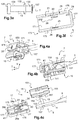
- a second embodiment is illustrated on the figures 3a to 3f . Only the different elements of the first embodiment are described below.
- connection device 7 ( figures 3a to 3d ) is configured to cooperate with a wiper arm 5 which differs from the first embodiment by the transverse axis 13.
- the transverse axis 13, better visible on the figure 3e comprises a collar 132, for example formed by two successive shoulders.
- the transverse axis 13 has a first section 133 configured to be assembled to the connector 15 (not visible on the figure 3e ) and a second section 135 configured to be assembled at the longitudinal end 11 of the wiper arm 5 (not visible on the figure 3e ).
- the collar 132 is located between the first section 133 and the second section 135.
- the first and second sections 133 and 135 of the transverse axis 13, on either side of the collar 132, can be of the same diameter.
- the collar 132 has, according to the second embodiment, a bearing surface on the longitudinal end 11, of the wiper arm 5 in the assembled state of the transverse axis 13 and of the longitudinal end 11, as this is visible on figures 3b to 3d .
- the transverse axis 13 also includes a base 136 at the free end of the first section 133.
- the first section 133 is intended to be mounted in the connector 15, so that the collar 132 and the base 136 are arranged in abutment or abutment against the external faces of the side walls 157 of the connector 15 (see 3d figure ).
- the term “external face” of a side wall 157 is understood to mean the face intended to be arranged facing the internal face of a side wall 175 of the cover 17 in the assembled state of the connection device 7.
- the transverse axis 13 may further include an end 137 of diameter greater than the second section 135, for example formed by snap-fastening.
- the second section 135 is interposed between the collar 132 and the end 137.
- the connector 15 As regards the connector 15, according to this second embodiment, it is the second part 153 or part for connecting to the wiper arm 5 differs from the first embodiment.
- the means for assembling the two lateral walls 157 to the transverse axis 13 are no longer produced in the form of an orifice 159, as in the first embodiment but in the form of notches 159 ′ (see figures 3b to 3d ).
- the notches 159 ′ and in particular their shape and their size, are suitable for the first section 133 of the transverse axis 13, but do not allow the collar 132 and the base 136 to pass inside the connector 15 , that is to say between the internal faces of the two side walls 157.
- the orifice 25 is configured to receive the base 136 of the transverse axis 13 (not visible on the figure 3f ), in the assembled state of the cover 17 to the terminal segment 9 of the wiper arm 5.
- the fixing means 23 may no longer include protuberances 27 formed on the upper wall 171 of the cover 17, previously described with reference to figures 2e, 2g of the first embodiment.
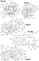
- a third embodiment is illustrated on the Figures 4a to 4h . Only the different elements of the first embodiment are described below.
- the cover 17 is configured for assembly to the connector 15 by longitudinal translation, substantially parallel to the longitudinal direction L.
- translation is understood to be substantially parallel, a translation parallel to the longitudinal direction L or in a direction approaching a direction parallel to the longitudinal direction L.
- the cover 17 may include one or more means for guiding the connector 15 and / or the terminal segment 9.
- the lower part 173 of the cover 17 comprises a holding means 19 made in one piece with the cover 17 and comprising a relief 21 '(see figures 4d, 4f, and 4h ).
- the same relief 21 ' extends over more than half of the length of the cover 17. According to the example illustrated, the relief 21' extends over almost the entire length of the cover 17.
- the relief 21 ′ protrudes over the lower or lower portion of the side wall 175, extending towards the inside of the cover 17.
- this is in particular a guide relief 21 'configured to guide the terminal segment 9 of the wiper arm 5 during the assembly of the terminal segment 9 of the wiper arm 5 to the cover 17.
- the relief 21 ′ therefore acts as a means of guiding the terminal segment 9 of the wiper arm 5.
- the relief 21 ′ may have a shape similar to that of the reliefs 21 of the first embodiment.
- the cover 17 may include at least one partition 41 forming a stop for the terminal segment 9 of the wiper arm 5.
- This partition 41 is arranged at the end of the relief 21 'opposite the end wall 177.
- This partition 41 extends towards the inside of the cover 17, in particular, along a plane parallel to the plane T, V, substantially parallel to the end wall 177. In other words, the partition 41 extends parallel to the end wall 177 or almost parallel to the end wall 177.
- the partition 41 and the relief 21 ′ can be formed without material discontinuity.
- the cover 17 includes a guide for the end 137 of the transverse axis 13 during the introduction of the terminal segment 9 of the wiper arm 5 into the cover 17, for example made in the form of a recess 22 '(see figures 4f and 4g ) on the side wall 175 having the relief 21 '.
- the recess 22 ′ has, for example, a substantially “U” shape. In other words, the recess 22 ′ has a “U” shape or equivalent.
- the shape of the "U” is suitable for longitudinal translation and no longer for vertical sliding.
- the branches of the "U” extend longitudinally in the longitudinal direction L.
- the branches of the "U” extend in parallel or almost parallel, to the relief 21 '.
- the base of the "U” is oriented towards the end wall 177 of the cover 17.
- the recess 22 ' is located above the relief 21'.
- the fixing means 23 comprises at least one orifice 25 'formed on the cover 17.
- the orifice 25 ' is provided on the side wall 175 of the cover 17 opposite the side wall 175 carrying the relief 21'.
- the transverse axis 13 is inserted into the orifice 25 'during the assembly of the terminal segment 9 of the wiper arm 5 to the cover 17. In particular, it is the free end of the first section 133 of the transverse axis 13 which is received in the orifice 25 '.
- the slope 26 ′ is arranged so as to start from the side edge, and no longer from the bottom edge, from the side wall 175 of the cover 17 having the orifice 25 ′, to end in forming a portion of the outline of the orifice 25 '.
- the side wall 175 having the slope 26 ' comprises at least one rib 43, defined by the rim of the cutout to produce the slope 26'.
- This rib 43 advantageously performs a function of guiding the connector 15 to the assembly of the connection device 7.
- a side wall 157 of the connector 15, in particular the top of this side wall 157, can slide on the rib 43.
- the fastening means 23 may no longer include protrusions 27 formed on the upper part 171 of the cover 17 previously described with reference to figures 2e, 2g of the first embodiment.
- the fixing means 23 can comprise at least one fixing wall 28a.
- at least two fixing walls 28a are provided. These fixing walls 28a extend from the upper part 171 of the cover 17 towards the inside of the cover 17, more precisely from the internal face of the upper wall 171 forming the upper part of the cover 17 according to the embodiments described.
- the fixing walls 28a extend substantially parallel to the side walls 175 of the cover 17. In other words, the fixing walls 28a extend parallel or almost parallel to the side walls 175 of the cover 17.
- the fixing walls 28a extend in this example along a plane parallel to the plane L, V.
- One of the fixing walls 28a is arranged opposite the side wall 175 of the cover 17 on which the orifice 25 'is provided.
- the other fixing wall 28a is arranged opposite the side wall 175 of the cover 17 having the recess 22 '.
- the two fixing walls 28a are arranged opposite one another.
- the fixing walls 28a respectively have a notch 281.
- this transverse axis 13 engages in the notches 281.
- the two notches 281, the orifice 25 'and the recess 22' are aligned in the transverse direction T.
- the notches 281 are of shape complementary to the shape of the transverse axis 13, in particular of the first section 133.
- the notches 281 are of substantially “U” shape according to the example illustrated. That is to say, the notches 281 are of "U” shape or of equivalent or similar shape, approaching the "U”.
- the fixing walls 28a act as attachment walls or hooks for fixing the transverse axis 13.
- An additional wall 28b can also be provided making the junction between the two fixing walls 28a.
- the junction wall 28b extends opposite the end wall 177.
- This junction wall 28b in this example extends parallel, or almost parallel, to the end wall 177.
- All of the fixing walls 28a and junction 28b have in the example illustrated a section substantially in “U”, that is to say in “U” or of a shape approaching "U”, as this is best seen on the figure 4h .
- the cover 17 may comprise, on the upper part 171 of the cover 17, a single stop 29 ', rather than several separate stops 29 as described in the first embodiment with reference to figures 2b and 2g .
- This stop 29 ' also allows the adjustment of the mounting of the terminal segment 9 of the wiper arm 5 in the cover 17.
- a user can slide the cover 17 so that the longitudinal end 11 of the wiper arm 5 slides relative to the relief 21 '.
- At least the side wall 175 having the orifice 25 ' is deformed due to the upward slope 26' which leads to the orifice 25 '.
- the cover 17 and the holding means 19 of the terminal segment 9 of the wiper arm 5, and advantageously the fixing means 23 of the transverse axis 13 carried by the cover 17, are made in one piece.
- the holding means 19 of the terminal segment 9 of the wiper arm 5, are distinct from the fixing means 23 of the transverse axis 13.
- a cover 17 and the means necessary for the simple assembly of the connection device 7 on the wiper arm 5 are thus produced in one piece.
- the locking can be do it simply by snap-fastening during assembly, without requiring any complicated additional handling.
- the holding means 19 and / or the fixing means 23 are advantageously shaped so as to prevent tearing of the cover 17 and / or of the connector 15 and / or of the wiper arm 5, in the vertical direction. V.
- the fixing means 23 are configured to longitudinally block the movement of the connector 15 in which the transverse axis 13 is mounted, relative to the cover 17.
- the holding means 19 and / or the fixing means 23 allow reversible locking of the connection device 7 on the wiper arm 5.
Claims (16)
- Abdeckung (17), die dazu konfiguriert ist, mit einem Endstück (9) eines Scheibenwischerarms (5) zusammengefügt zu werden, der dazu konfiguriert ist, mit einem Scheibenwischerblatt (3) verbunden zu werden, wobei das Endstück (19) ein Längsende (11) aufweist, das eine Querachse (13) trägt, die dazu konfiguriert ist, eine Schwenkachse des Scheibenwischerblatts (3) zu definieren, wobei die Abdeckung (17) Folgendes umfasst:- einen oberen Abschnitt (171), der dazu konfiguriert ist, das Endstück (9) des Scheibenwischerarms (5) abzudecken, wenn die Abdeckung (17) mit dem Endstück (9) zusammengefügt ist,- einen unteren Abschnitt (173), der dem oberen Abschnitt (171) gegenüberliegt, und- mindestens ein Befestigungsmittel (23), das dazu konfiguriert ist, mit der Querachse (13) zusammenzuwirken, um die Querachse (13) an der Abdeckung (17) zu befestigen,dadurch gekennzeichnet, dass der untere Abschnitt (173) der Abdeckung (17) mindestens ein Haltemittel (19) umfasst, das als ein Stück mit der Abdeckung (17) ausgebildet ist und dazu konfiguriert ist, mit dem Endstück (9) des Scheibenwischerarms (5) zusammenzuwirken, um die Abdeckung (17) mit dem Endstück (9) des Scheibenwischerarms (5) zusammenzufügen.
- Abdeckung (17) nach dem vorhergehenden Anspruch, wobei das mindestens eine Haltemittel (19) mindestens ein Relief (21; 21') umfasst, das an dem unteren Abschnitt (173) der Abdeckung (17) gebildet ist.
- Abdeckung (17) nach dem vorhergehenden Anspruch, die zwei gegenüberliegende Seitenwände (175) umfasst, die sich von dem oberen Abschnitt (171) der Abdeckung (17) erstrecken, und wobei das mindestens eine Relief (21; 21') auf einem unteren Abschnitt mindestens einer Seitenwand (175) gebildet ist.
- Abdeckung (17) nach einem der vorhergehenden Ansprüche, wobei das mindestens eine Haltemittel (19) mindestens ein Einrastrelief (21) umfasst, das dazu konfiguriert ist, das Entfernen des Endstücks (9) von dem Scheibenwischerarm (5) zu blockieren, wenn das Endstück (9) mit der Abdeckung (17) zusammengefügt ist.
- Abdeckung (17) nach einem der vorhergehenden Ansprüche, wobei das mindestens eine Haltemittel (19) mindestens ein Führungsrelief (21; 21') umfasst, das dazu konfiguriert ist, das Endstück (9) des Scheibenwischerarms (5) während des Zusammenfügens des Endstücks (9) des Scheibenwischerarms (5) mit der Abdeckung (17) zu führen.
- Abdeckung (17) nach einem der Ansprüche 2 bis 5, die eine Längsform aufweist, wobei sich das mindestens eine Relief (21; 21') entlang der Längsrichtung (L) der Abdeckung (17) erstreckt.
- Abdeckung (17) nach Anspruch 6, die ein gleiches Relief (21') beinhaltet, das sich über mehr als die Hälfte der Länge der Abdeckung (17) erstreckt.
- Abdeckung (17) nach einem der Ansprüche 2 bis 6, die mindestens zwei verschiedene Reliefs (21) beinhaltet.
- Abdeckung (17) nach einem der Ansprüche 2 bis 8, wobei das mindestens eine Relief (21; 21') Folgendes umfasst:- eine Anschlagfläche (213), die eine Kante bildet, wobei das Endstück (9) des Scheibenwischerarms (5) dazu konfiguriert ist, an dieser anzuliegen, wenn das Endstück (9) mit der Abdeckung (17) zusammengefügt ist.
- Abdeckung (17) nach einem der vorhergehenden Ansprüche, wobei das mindestens eine Befestigungsmittel (23) mindestens ein an der Abdeckung (17) gebildetes Loch (25; 25') umfasst.
- Abdeckung (17) nach Anspruch 10, wobei das Loch (25) ein Sackloch ist.
- Abdeckung (17) nach Anspruch 10, wobei das Loch (25') ein Durchgangsloch ist.
- Abdeckung (17) nach einem der vorhergehenden Ansprüche, wobei das mindestens eine Befestigungsmittel (23) mindestens zwei Vorsprünge (27) umfasst, die an dem oberen Abschnitt (171) der Abdeckung (17) gebildet sind.
- Abdeckung (17) nach einem der vorhergehenden Ansprüche, wobei das mindestens eine Befestigungsmittel (23) mindestens eine Befestigungswand (28a) oder sogar mindestens zwei Wände beinhaltet, die sich von dem oberen Abschnitt (171) der Abdeckung (17) ins Innere der Abdeckung (17) erstrecken und die jeweils eine Einkerbung (281) aufweisen, wobei die Querachse (13), die von dem Scheibenwischerarm (5) getragen wird, dazu konfiguriert ist, mit dieser in Eingriff zu kommen.
- Verbindungsvorrichtung (7) für die Montage eines Scheibenwischerblatts (3) an einem Scheibenwischerarm (5), wobei die Verbindungsvorrichtung (7) Folgendes umfasst:- ein Verbindungsstück (15), das dazu konfiguriert ist, mit dem Scheibenwischerblatt (3) einerseits und dem Scheibenwischerarm (5) andererseits verbunden zu werden, und- eine Abdeckung (17), die dazu konfiguriert ist, mit dem Verbindungsstück (15) zusammenzuwirken, um das Scheibenwischerblatt (3) an dem Scheibenwischerarm (5) zu befestigen,dadurch gekennzeichnet, dass die Abdeckung (17) einem der vorhergehenden Ansprüche entspricht.
- Scheibenwischsystem eines Kraftfahrzeugs, das mindestens ein Scheibenwischerblatt (3) umfasst, dadurch gekennzeichnet, dass es eine Verbindungsvorrichtung (7) nach dem vorhergehenden Anspruch umfasst.
Applications Claiming Priority (1)
| Application Number | Priority Date | Filing Date | Title |
|---|---|---|---|
| FR1752075A FR3063950B1 (fr) | 2017-03-14 | 2017-03-14 | Capot, dispositif de connexion pour le montage d’un balai d’essuie-glace sur un bras d’essuie-glace et systeme d’essuyage correspondants |
Publications (2)
| Publication Number | Publication Date |
|---|---|
| EP3375675A1 EP3375675A1 (de) | 2018-09-19 |
| EP3375675B1 true EP3375675B1 (de) | 2020-02-05 |
Family
ID=58993035
Family Applications (1)
| Application Number | Title | Priority Date | Filing Date |
|---|---|---|---|
| EP18161105.4A Active EP3375675B1 (de) | 2017-03-14 | 2018-03-09 | Abdeckung, verbindungsvorrichtung für die montage eines scheibenwischerblatts auf einem entsprechenden scheibenwischerarm, und entsprechendes scheibenwischsystem |
Country Status (4)
| Country | Link |
|---|---|
| US (1) | US10780863B2 (de) |
| EP (1) | EP3375675B1 (de) |
| CN (1) | CN108569252B (de) |
| FR (1) | FR3063950B1 (de) |
Families Citing this family (1)
| Publication number | Priority date | Publication date | Assignee | Title |
|---|---|---|---|---|
| FR3105768B1 (fr) * | 2019-12-27 | 2022-06-17 | Valeo Systemes Dessuyage | Système d'essuyage pour véhicule automobile |
Family Cites Families (17)
| Publication number | Priority date | Publication date | Assignee | Title |
|---|---|---|---|---|
| DE10259480A1 (de) * | 2002-06-28 | 2004-01-15 | Robert Bosch Gmbh | Wischblatt |
| DE10259477B4 (de) * | 2002-12-19 | 2020-12-10 | Robert Bosch Gmbh | Verhinderungsanordnung einer Wischvorrichtung für Scheiben von Kraftfahrzeugen |
| CN100584673C (zh) * | 2005-02-03 | 2010-01-27 | 罗伯特·博世有限公司 | 将刮水片与挡风玻璃刮水器的刮水臂铰接地连接的装置 |
| ES2403059T3 (es) * | 2008-09-13 | 2013-05-13 | Robert Bosch Gmbh | Dispositivo de conexión para la conexión articulada de una escobilla del limpiaparabrisas con un brazo del limpiaparabrisas |
| US9168897B2 (en) * | 2009-10-12 | 2015-10-27 | Federal-Mogul S.A. | Windscreen wiper device |
| TWM404153U (en) * | 2010-09-07 | 2011-05-21 | Zhi-Ming Yang | Joining structure applicable for windshield wiper |
| US9889823B2 (en) * | 2010-12-02 | 2018-02-13 | Valeo Systèmes d'Essuyage | Hydraulic connector for a windshield wiper blade having a retractable button |
| DE102011079783A1 (de) * | 2011-07-26 | 2013-01-31 | Robert Bosch Gmbh | Anschlussvorrichtung zum gelenkigen Verbinden eines Wischblatts mit einem Wischarm und ein Adapter |
| US9688251B2 (en) * | 2012-01-20 | 2017-06-27 | Dongguan Hongyi Wiper Co., Ltd. | Wiper connector and bolt-stabilizing sleeve adaptor |
| KR101369629B1 (ko) * | 2012-04-06 | 2014-03-04 | 주식회사 캐프 | 차량용 와이퍼 장치 |
| DE102012209956A1 (de) * | 2012-06-14 | 2013-12-19 | Robert Bosch Gmbh | Wischblattadaptersystem |
| DE102012210544A1 (de) * | 2012-06-21 | 2013-12-24 | Robert Bosch Gmbh | Wischadaptervorrichtung |
| US9555775B2 (en) * | 2013-03-15 | 2017-01-31 | Illinois Tool Works Inc. | Connectors and connector kit for attachment of a windshield wiper blade to multiple types of windshield wiper arms |
| FR3011211B1 (fr) * | 2013-09-30 | 2017-01-13 | Valeo Systemes Dessuyage | Connecteur ou adaptateur pour systeme d'essuyage d'un pare-brise, notamment de vehicule automobile |
| FR3031712B1 (fr) * | 2015-01-16 | 2018-10-12 | Valeo Systemes D'essuyage | Capot d’essuie-glace configure pour recouvrir une partie terminale d’un bras d’essuie-glace |
| FR3037901A1 (fr) * | 2015-06-29 | 2016-12-30 | Valeo Systemes Dessuyage | Adaptateur pour relier un balai d'essuie-glace a un bras d'entrainement |
| FR3046762B1 (fr) * | 2016-01-15 | 2018-01-26 | Valeo Systemes D'essuyage | Embout d'extremite pour un balai d'essuie-glace de vehicule |
-
2017
- 2017-03-14 FR FR1752075A patent/FR3063950B1/fr not_active Expired - Fee Related
-
2018
- 2018-03-09 EP EP18161105.4A patent/EP3375675B1/de active Active
- 2018-03-13 US US15/919,598 patent/US10780863B2/en active Active
- 2018-03-14 CN CN201810208315.3A patent/CN108569252B/zh active Active
Non-Patent Citations (1)
| Title |
|---|
| None * |
Also Published As
| Publication number | Publication date |
|---|---|
| FR3063950A1 (fr) | 2018-09-21 |
| EP3375675A1 (de) | 2018-09-19 |
| CN108569252B (zh) | 2021-07-27 |
| FR3063950B1 (fr) | 2019-04-19 |
| US20180265046A1 (en) | 2018-09-20 |
| US10780863B2 (en) | 2020-09-22 |
| CN108569252A (zh) | 2018-09-25 |
Similar Documents
| Publication | Publication Date | Title |
|---|---|---|
| WO2004024520A1 (fr) | Agencement de fixation d'un balai d'essuie glace sur un bras | |
| EP3168093B1 (de) | Adapter für ein kraftfahrzeugwischerblatt | |
| EP3135547B1 (de) | Halteelement, scheibenwischerblatt und scheibenwischer eines kraftfahrzeugs | |
| EP3231673A1 (de) | Reinigungssystem der windschutzscheibe eines fahrzeugs | |
| EP3045357B1 (de) | Abdeckung eines scheibenwischers, die für die abdeckung des endteils eines scheibenwischerarms konfiguriert ist | |
| EP2965958B1 (de) | Einheit aus einem mechanischen anschluss und einer kanüle für ein scheibenwischerblatt eines fahrzeugs | |
| EP3375675B1 (de) | Abdeckung, verbindungsvorrichtung für die montage eines scheibenwischerblatts auf einem entsprechenden scheibenwischerarm, und entsprechendes scheibenwischsystem | |
| EP3081439B1 (de) | Endstück für scheibenwischer | |
| EP2965957B1 (de) | Schwenkbares verbindungselement für ein scheibenwischerblatt eines fahrzeugs | |
| EP2803544B1 (de) | Einheit zur Umsetzung eines Scheibenwischsystems für Kraftfahrzeug, und Verbindungsvorrichtung, die eine solche Einheit umfasst | |
| EP3012163B1 (de) | Vorrichtung zum spritzen von scheibenwaschflüssigkeit für einen scheibenwischerarm des scheibenwischersystems eines fahrzeugs | |
| EP3902710B1 (de) | Adapter für eine kraftfahrzeugwischerblatthalterung | |
| EP3366531B1 (de) | Anpassbare endkappe für ein wischblatt | |
| WO2021047812A1 (fr) | Maneton, boîte à rotule et système de tringlerie d'actionnement d'essuie-glaces correspondant et son procédé d'assemblage | |
| FR2731191A1 (fr) | Essuie-glace de vehicule automobile | |
| EP3112228B1 (de) | Organ für ein verbindungssystem eines wischerblatts an einen scheibenwischerarm | |
| EP1470942B1 (de) | Anordnung für die Befestigung eines Trägers für einen Sonnenvorhang | |
| EP3434536B1 (de) | Befestigungsvorrichtung für ein gestängesystem zur betätigung von scheibenwischern | |
| WO2022171832A1 (fr) | Adaptateur d'un système d'essuyage | |
| EP3402703B1 (de) | Adapter zum anschliessen eines wischblatts an einem antriebsarm | |
| EP3248848B1 (de) | Befestigungsvorrichtung für die montage eines scheibenwischerblatts auf einem scheibenwischerarm, und entsprechendes scheibenwischsystem | |
| WO2020239709A1 (fr) | Chape pour bras d'entraînement | |
| WO2023208726A1 (fr) | Ensemble de connexion d'un système d'essuyage | |
| WO2023110974A1 (fr) | Embout d'extrémité et balai d'essuie-glace pour véhicule automobile | |
| EP4124518A1 (de) | Verbindungsvorrichtung zwischen wischblatt und antriebsarm |
Legal Events
| Date | Code | Title | Description |
|---|---|---|---|
| PUAI | Public reference made under article 153(3) epc to a published international application that has entered the european phase |
Free format text: ORIGINAL CODE: 0009012 |
|
| STAA | Information on the status of an ep patent application or granted ep patent |
Free format text: STATUS: REQUEST FOR EXAMINATION WAS MADE |
|
| 17P | Request for examination filed |
Effective date: 20180309 |
|
| AK | Designated contracting states |
Kind code of ref document: A1 Designated state(s): AL AT BE BG CH CY CZ DE DK EE ES FI FR GB GR HR HU IE IS IT LI LT LU LV MC MK MT NL NO PL PT RO RS SE SI SK SM TR |
|
| AX | Request for extension of the european patent |
Extension state: BA ME |
|
| GRAP | Despatch of communication of intention to grant a patent |
Free format text: ORIGINAL CODE: EPIDOSNIGR1 |
|
| STAA | Information on the status of an ep patent application or granted ep patent |
Free format text: STATUS: GRANT OF PATENT IS INTENDED |
|
| RIC1 | Information provided on ipc code assigned before grant |
Ipc: B60S 1/40 20060101AFI20190814BHEP |
|
| INTG | Intention to grant announced |
Effective date: 20190830 |
|
| GRAS | Grant fee paid |
Free format text: ORIGINAL CODE: EPIDOSNIGR3 |
|
| GRAA | (expected) grant |
Free format text: ORIGINAL CODE: 0009210 |
|
| STAA | Information on the status of an ep patent application or granted ep patent |
Free format text: STATUS: THE PATENT HAS BEEN GRANTED |
|
| AK | Designated contracting states |
Kind code of ref document: B1 Designated state(s): AL AT BE BG CH CY CZ DE DK EE ES FI FR GB GR HR HU IE IS IT LI LT LU LV MC MK MT NL NO PL PT RO RS SE SI SK SM TR |
|
| REG | Reference to a national code |
Ref country code: GB Ref legal event code: FG4D Free format text: NOT ENGLISH |
|
| REG | Reference to a national code |
Ref country code: AT Ref legal event code: REF Ref document number: 1229687 Country of ref document: AT Kind code of ref document: T Effective date: 20200215 |
|
| REG | Reference to a national code |
Ref country code: DE Ref legal event code: R096 Ref document number: 602018002277 Country of ref document: DE |
|
| REG | Reference to a national code |
Ref country code: IE Ref legal event code: FG4D Free format text: LANGUAGE OF EP DOCUMENT: FRENCH |
|
| REG | Reference to a national code |
Ref country code: CH Ref legal event code: EP |
|
| PGFP | Annual fee paid to national office [announced via postgrant information from national office to epo] |
Ref country code: BE Payment date: 20200330 Year of fee payment: 3 |
|
| REG | Reference to a national code |
Ref country code: NL Ref legal event code: MP Effective date: 20200205 |
|
| PG25 | Lapsed in a contracting state [announced via postgrant information from national office to epo] |
Ref country code: NO Free format text: LAPSE BECAUSE OF FAILURE TO SUBMIT A TRANSLATION OF THE DESCRIPTION OR TO PAY THE FEE WITHIN THE PRESCRIBED TIME-LIMIT Effective date: 20200505 Ref country code: RS Free format text: LAPSE BECAUSE OF FAILURE TO SUBMIT A TRANSLATION OF THE DESCRIPTION OR TO PAY THE FEE WITHIN THE PRESCRIBED TIME-LIMIT Effective date: 20200205 Ref country code: FI Free format text: LAPSE BECAUSE OF FAILURE TO SUBMIT A TRANSLATION OF THE DESCRIPTION OR TO PAY THE FEE WITHIN THE PRESCRIBED TIME-LIMIT Effective date: 20200205 Ref country code: PT Free format text: LAPSE BECAUSE OF FAILURE TO SUBMIT A TRANSLATION OF THE DESCRIPTION OR TO PAY THE FEE WITHIN THE PRESCRIBED TIME-LIMIT Effective date: 20200628 |
|
| REG | Reference to a national code |
Ref country code: LT Ref legal event code: MG4D |
|
| PG25 | Lapsed in a contracting state [announced via postgrant information from national office to epo] |
Ref country code: SE Free format text: LAPSE BECAUSE OF FAILURE TO SUBMIT A TRANSLATION OF THE DESCRIPTION OR TO PAY THE FEE WITHIN THE PRESCRIBED TIME-LIMIT Effective date: 20200205 Ref country code: LV Free format text: LAPSE BECAUSE OF FAILURE TO SUBMIT A TRANSLATION OF THE DESCRIPTION OR TO PAY THE FEE WITHIN THE PRESCRIBED TIME-LIMIT Effective date: 20200205 Ref country code: HR Free format text: LAPSE BECAUSE OF FAILURE TO SUBMIT A TRANSLATION OF THE DESCRIPTION OR TO PAY THE FEE WITHIN THE PRESCRIBED TIME-LIMIT Effective date: 20200205 Ref country code: BG Free format text: LAPSE BECAUSE OF FAILURE TO SUBMIT A TRANSLATION OF THE DESCRIPTION OR TO PAY THE FEE WITHIN THE PRESCRIBED TIME-LIMIT Effective date: 20200505 Ref country code: IS Free format text: LAPSE BECAUSE OF FAILURE TO SUBMIT A TRANSLATION OF THE DESCRIPTION OR TO PAY THE FEE WITHIN THE PRESCRIBED TIME-LIMIT Effective date: 20200605 Ref country code: GR Free format text: LAPSE BECAUSE OF FAILURE TO SUBMIT A TRANSLATION OF THE DESCRIPTION OR TO PAY THE FEE WITHIN THE PRESCRIBED TIME-LIMIT Effective date: 20200506 |
|
| PG25 | Lapsed in a contracting state [announced via postgrant information from national office to epo] |
Ref country code: NL Free format text: LAPSE BECAUSE OF FAILURE TO SUBMIT A TRANSLATION OF THE DESCRIPTION OR TO PAY THE FEE WITHIN THE PRESCRIBED TIME-LIMIT Effective date: 20200205 |
|
| PG25 | Lapsed in a contracting state [announced via postgrant information from national office to epo] |
Ref country code: RO Free format text: LAPSE BECAUSE OF FAILURE TO SUBMIT A TRANSLATION OF THE DESCRIPTION OR TO PAY THE FEE WITHIN THE PRESCRIBED TIME-LIMIT Effective date: 20200205 Ref country code: CZ Free format text: LAPSE BECAUSE OF FAILURE TO SUBMIT A TRANSLATION OF THE DESCRIPTION OR TO PAY THE FEE WITHIN THE PRESCRIBED TIME-LIMIT Effective date: 20200205 Ref country code: SK Free format text: LAPSE BECAUSE OF FAILURE TO SUBMIT A TRANSLATION OF THE DESCRIPTION OR TO PAY THE FEE WITHIN THE PRESCRIBED TIME-LIMIT Effective date: 20200205 Ref country code: LT Free format text: LAPSE BECAUSE OF FAILURE TO SUBMIT A TRANSLATION OF THE DESCRIPTION OR TO PAY THE FEE WITHIN THE PRESCRIBED TIME-LIMIT Effective date: 20200205 Ref country code: DK Free format text: LAPSE BECAUSE OF FAILURE TO SUBMIT A TRANSLATION OF THE DESCRIPTION OR TO PAY THE FEE WITHIN THE PRESCRIBED TIME-LIMIT Effective date: 20200205 Ref country code: ES Free format text: LAPSE BECAUSE OF FAILURE TO SUBMIT A TRANSLATION OF THE DESCRIPTION OR TO PAY THE FEE WITHIN THE PRESCRIBED TIME-LIMIT Effective date: 20200205 Ref country code: EE Free format text: LAPSE BECAUSE OF FAILURE TO SUBMIT A TRANSLATION OF THE DESCRIPTION OR TO PAY THE FEE WITHIN THE PRESCRIBED TIME-LIMIT Effective date: 20200205 Ref country code: SM Free format text: LAPSE BECAUSE OF FAILURE TO SUBMIT A TRANSLATION OF THE DESCRIPTION OR TO PAY THE FEE WITHIN THE PRESCRIBED TIME-LIMIT Effective date: 20200205 |
|
| REG | Reference to a national code |
Ref country code: DE Ref legal event code: R097 Ref document number: 602018002277 Country of ref document: DE |
|
| REG | Reference to a national code |
Ref country code: AT Ref legal event code: MK05 Ref document number: 1229687 Country of ref document: AT Kind code of ref document: T Effective date: 20200205 |
|
| PG25 | Lapsed in a contracting state [announced via postgrant information from national office to epo] |
Ref country code: MC Free format text: LAPSE BECAUSE OF FAILURE TO SUBMIT A TRANSLATION OF THE DESCRIPTION OR TO PAY THE FEE WITHIN THE PRESCRIBED TIME-LIMIT Effective date: 20200205 |
|
| PLBE | No opposition filed within time limit |
Free format text: ORIGINAL CODE: 0009261 |
|
| STAA | Information on the status of an ep patent application or granted ep patent |
Free format text: STATUS: NO OPPOSITION FILED WITHIN TIME LIMIT |
|
| PG25 | Lapsed in a contracting state [announced via postgrant information from national office to epo] |
Ref country code: LU Free format text: LAPSE BECAUSE OF NON-PAYMENT OF DUE FEES Effective date: 20200309 |
|
| 26N | No opposition filed |
Effective date: 20201106 |
|
| PG25 | Lapsed in a contracting state [announced via postgrant information from national office to epo] |
Ref country code: AT Free format text: LAPSE BECAUSE OF FAILURE TO SUBMIT A TRANSLATION OF THE DESCRIPTION OR TO PAY THE FEE WITHIN THE PRESCRIBED TIME-LIMIT Effective date: 20200205 Ref country code: IE Free format text: LAPSE BECAUSE OF NON-PAYMENT OF DUE FEES Effective date: 20200309 Ref country code: IT Free format text: LAPSE BECAUSE OF FAILURE TO SUBMIT A TRANSLATION OF THE DESCRIPTION OR TO PAY THE FEE WITHIN THE PRESCRIBED TIME-LIMIT Effective date: 20200205 |
|
| PG25 | Lapsed in a contracting state [announced via postgrant information from national office to epo] |
Ref country code: PL Free format text: LAPSE BECAUSE OF FAILURE TO SUBMIT A TRANSLATION OF THE DESCRIPTION OR TO PAY THE FEE WITHIN THE PRESCRIBED TIME-LIMIT Effective date: 20200205 Ref country code: SI Free format text: LAPSE BECAUSE OF FAILURE TO SUBMIT A TRANSLATION OF THE DESCRIPTION OR TO PAY THE FEE WITHIN THE PRESCRIBED TIME-LIMIT Effective date: 20200205 |
|
| REG | Reference to a national code |
Ref country code: CH Ref legal event code: PL |
|
| REG | Reference to a national code |
Ref country code: BE Ref legal event code: MM Effective date: 20210331 |
|
| PG25 | Lapsed in a contracting state [announced via postgrant information from national office to epo] |
Ref country code: LI Free format text: LAPSE BECAUSE OF NON-PAYMENT OF DUE FEES Effective date: 20210331 Ref country code: CH Free format text: LAPSE BECAUSE OF NON-PAYMENT OF DUE FEES Effective date: 20210331 |
|
| PG25 | Lapsed in a contracting state [announced via postgrant information from national office to epo] |
Ref country code: TR Free format text: LAPSE BECAUSE OF FAILURE TO SUBMIT A TRANSLATION OF THE DESCRIPTION OR TO PAY THE FEE WITHIN THE PRESCRIBED TIME-LIMIT Effective date: 20200205 Ref country code: MT Free format text: LAPSE BECAUSE OF FAILURE TO SUBMIT A TRANSLATION OF THE DESCRIPTION OR TO PAY THE FEE WITHIN THE PRESCRIBED TIME-LIMIT Effective date: 20200205 Ref country code: CY Free format text: LAPSE BECAUSE OF FAILURE TO SUBMIT A TRANSLATION OF THE DESCRIPTION OR TO PAY THE FEE WITHIN THE PRESCRIBED TIME-LIMIT Effective date: 20200205 |
|
| PG25 | Lapsed in a contracting state [announced via postgrant information from national office to epo] |
Ref country code: MK Free format text: LAPSE BECAUSE OF FAILURE TO SUBMIT A TRANSLATION OF THE DESCRIPTION OR TO PAY THE FEE WITHIN THE PRESCRIBED TIME-LIMIT Effective date: 20200205 Ref country code: AL Free format text: LAPSE BECAUSE OF FAILURE TO SUBMIT A TRANSLATION OF THE DESCRIPTION OR TO PAY THE FEE WITHIN THE PRESCRIBED TIME-LIMIT Effective date: 20200205 |
|
| PG25 | Lapsed in a contracting state [announced via postgrant information from national office to epo] |
Ref country code: BE Free format text: LAPSE BECAUSE OF NON-PAYMENT OF DUE FEES Effective date: 20210331 |
|
| GBPC | Gb: european patent ceased through non-payment of renewal fee |
Effective date: 20220309 |
|
| PG25 | Lapsed in a contracting state [announced via postgrant information from national office to epo] |
Ref country code: GB Free format text: LAPSE BECAUSE OF NON-PAYMENT OF DUE FEES Effective date: 20220309 |
|
| PGFP | Annual fee paid to national office [announced via postgrant information from national office to epo] |
Ref country code: FR Payment date: 20230320 Year of fee payment: 6 |
|
| PGFP | Annual fee paid to national office [announced via postgrant information from national office to epo] |
Ref country code: DE Payment date: 20230307 Year of fee payment: 6 |
|
| P01 | Opt-out of the competence of the unified patent court (upc) registered |
Effective date: 20230528 |