EP3375675B1 - Cap, connecting device for mounting a windscreen wiper on a corresponding windscreen wiper arm and windscreen wiping system - Google Patents
Cap, connecting device for mounting a windscreen wiper on a corresponding windscreen wiper arm and windscreen wiping system Download PDFInfo
- Publication number
- EP3375675B1 EP3375675B1 EP18161105.4A EP18161105A EP3375675B1 EP 3375675 B1 EP3375675 B1 EP 3375675B1 EP 18161105 A EP18161105 A EP 18161105A EP 3375675 B1 EP3375675 B1 EP 3375675B1
- Authority
- EP
- European Patent Office
- Prior art keywords
- cap
- cover
- wiper arm
- windscreen wiper
- terminal segment
- Prior art date
- Legal status (The legal status is an assumption and is not a legal conclusion. Google has not performed a legal analysis and makes no representation as to the accuracy of the status listed.)
- Active
Links
Images


Classifications
-
- B—PERFORMING OPERATIONS; TRANSPORTING
- B60—VEHICLES IN GENERAL
- B60S—SERVICING, CLEANING, REPAIRING, SUPPORTING, LIFTING, OR MANOEUVRING OF VEHICLES, NOT OTHERWISE PROVIDED FOR
- B60S1/00—Cleaning of vehicles
- B60S1/02—Cleaning windscreens, windows or optical devices
- B60S1/04—Wipers or the like, e.g. scrapers
- B60S1/32—Wipers or the like, e.g. scrapers characterised by constructional features of wiper blade arms or blades
- B60S1/40—Connections between blades and arms
- B60S1/4067—Connections between blades and arms for arms provided with a side pin
- B60S1/4077—Connections between blades and arms for arms provided with a side pin characterised by the connecting part of, or an intermediate element mounted on, the wiper blade
-
- B—PERFORMING OPERATIONS; TRANSPORTING
- B60—VEHICLES IN GENERAL
- B60S—SERVICING, CLEANING, REPAIRING, SUPPORTING, LIFTING, OR MANOEUVRING OF VEHICLES, NOT OTHERWISE PROVIDED FOR
- B60S1/00—Cleaning of vehicles
- B60S1/02—Cleaning windscreens, windows or optical devices
- B60S1/04—Wipers or the like, e.g. scrapers
- B60S1/32—Wipers or the like, e.g. scrapers characterised by constructional features of wiper blade arms or blades
- B60S1/40—Connections between blades and arms
- B60S1/4067—Connections between blades and arms for arms provided with a side pin
- B60S1/407—Connections between blades and arms for arms provided with a side pin with means provided on the arm for locking the side pin
-
- B—PERFORMING OPERATIONS; TRANSPORTING
- B60—VEHICLES IN GENERAL
- B60S—SERVICING, CLEANING, REPAIRING, SUPPORTING, LIFTING, OR MANOEUVRING OF VEHICLES, NOT OTHERWISE PROVIDED FOR
- B60S1/00—Cleaning of vehicles
- B60S1/02—Cleaning windscreens, windows or optical devices
- B60S1/04—Wipers or the like, e.g. scrapers
- B60S1/32—Wipers or the like, e.g. scrapers characterised by constructional features of wiper blade arms or blades
- B60S1/40—Connections between blades and arms
- B60S1/4006—Connections between blades and arms for arms provided with a hook-shaped end
- B60S1/4009—Connections between blades and arms for arms provided with a hook-shaped end comprising a detachable intermediate element mounted on the hook-shaped end
- B60S1/4016—Connections between blades and arms for arms provided with a hook-shaped end comprising a detachable intermediate element mounted on the hook-shaped end the element being provided with retention means co-operating with the hook-shaped end of the arm
- B60S1/4019—Connections between blades and arms for arms provided with a hook-shaped end comprising a detachable intermediate element mounted on the hook-shaped end the element being provided with retention means co-operating with the hook-shaped end of the arm the retention means being protrusions or holes
Definitions
- the present invention relates to the fixing of a wiper blade on a wiper arm, in particular of a motor vehicle. It relates more particularly to a cover covering the connection between the arm and the wiper blade.
- the present invention also relates to a connection device for assembling the wiper blade to the wiper arm of a motor vehicle comprising such a cover.
- the invention also relates to a corresponding wiping system.
- a motor vehicle is fitted with wipers for cleaning a glazed surface such as the windshield.
- wipers generally comprise wiper arms, performing an angular reciprocating movement, and blades, themselves carrying scraper blades. These blades rub against the glass surface to evacuate cleaning liquid by bringing it outside the driver's field of vision.
- the blade is attached to the wiper arm by a connection device.
- the invention relates more particularly to a connection device for a wiper arm of the so-called lateral pivot or lateral pivot axis type, also known under the name "side lock" in English.
- a wiper arm has a terminal segment, configured to cooperate with the connector.
- This terminal segment comprises a first elongated element or longitudinal end extending substantially in the extension of the wiper arm.
- a substantially cylindrical rod extends perpendicularly from the longitudinal end of the wiper arm and forms a transverse axis.
- the connection device comprises a connector and a cover.
- the connector is a part intended to be secured to the wiper blade.
- the connector is also intended to be crossed by the transverse axis carried by the wiper arm, in order to link the connector to the end segment of the wiper arm by a pivot connection around the transverse axis.
- the wiper blade can pivot around the transverse axis, to adapt to the glass surface during the back and forth movement of the wiper.
- the cover is intended to be assembled and locked on the connector.
- connection device comprises means allowing the connection and the locking of the cover on the connector mounted on the wiper blade.
- DE 102.59.480 discloses a cover according to the preamble of claim 1.
- One of the aims of the present invention is to at least partially overcome these problems of the prior art by proposing a lower-cost alternative facilitating the mounting and dismounting of the cover on the connector intended to be connected to the wiper blade. window on the one hand and the wiper arm on the other hand via the transverse axis.
- the lower part of the cover comprises at least one holding means made in one piece with the cover and configured to cooperate with the end segment of the wiper arm for assembling the cover to the end segment. of the wiper arm.
- Such a cover is simple to produce.
- a movement in the tool is sufficient to produce the holding means integrally formed with the cover.
- the invention also relates to a motor vehicle wiping system comprising a connection device as defined above.
- the motor vehicle wiping system comprises at least one wiper blade.
- the wiping system 1 may or may not include the wiper arm 5.
- the wiper blade 3 extends longitudinally in a direction X.
- the wiper blade 3 comprises in particular a deflector 31 (or “spoiler” in English) and a wiping blade 33.
- the deflector 31 and the wiping blade 33 are made of flexible material.
- the wiper arm 5 extends longitudinally in a direction L.
- the wiper arm 5 has a terminal segment 9, better visible on the Figures 2a, 2b , configured to be connected to wiper blade 3. More specifically, the terminal segment 9 of the wiper arm 5 can be connected to the wiper blade 3 via the connection device 7.
- the terminal segment 9 has a longitudinal end 11.
- the longitudinal end 11 carries a transverse axis 13 configured to define a pivot axis of the wiper blade 3 (not visible on the Figures 2a, 2b ).
- the wiper arm 5 is said to have a lateral pivot or “side lock” in English.
- the transverse axis 13 is of generally substantially cylindrical shape. In other words, the transverse axis 13 is generally cylindrical or similar. This transverse axis 13 extends in the transverse direction T, perpendicular to the longitudinal direction L.
- connection device 7 allows the mounting and articulation of the wiper blade 3, also referring to the figure 1 , on the wiper arm 5, more precisely on the longitudinal end 11.
- the connection device 7 comprises for this purpose a connector 15 and a cover 17.
- Connector 15 ( Figures 2a to 2c ) is configured to be connected to the wiper blade 3 on the one hand and to the wiper arm 5 on the other hand ( figure 1 ).
- the connector 15 serves as an interface with the wiper blade 3 and the wiper arm 5.
- the cover 17 is configured to cooperate with the connector 15 so as to fix the wiper blade 3 to the wiper arm 5.
- the cover 17 allows in particular the locking of the assembly.
- the transverse axis 13 (visible on the Figures 2a, 2b ) is mounted in the connector 15 and held by the cover 17.
- the connector 15 and the cover 17 therefore cooperate to hold and fix the wiper blade 3 on the wiper arm 5.
- a connection device 7 can comprise different types of connectors 15 and covers 17. The differences between several embodiments of the connector 15 and of the cover 17 are explained below.
- connection device 7 is configured to cooperate with a transverse axis 13 of the wiping arm.
- the transverse axis comprises for example a shoulder 131 visible on the figure 2d . Therefore, the transverse axis 13 has a first section 133 of first diameter and a second section 135 of second diameter, for example less than the first diameter.
- the first section 133 is configured to be assembled to the connector 15 (not visible on the figure 2d ), and the second section 135 is configured to be assembled at the longitudinal end 11 of the wiper arm 5 (not visible on the figure 2d ).
- the shoulder 131 thus serves as a bearing surface at the longitudinal end 11 of the wiper arm 5 in the assembled state of the transverse axis 13 and the longitudinal end 11 (see figure 2e ).
- the transverse axis 13 may further include an end 137 of diameter greater than the second section 135.
- the end 137 may be formed after assembly of the transverse axis 13, more precisely of the second section 135, to the wiper arm ice 5 (see also Figures 2a, 2b , 2nd ), for example by bolting, so as to secure the longitudinal end 11 and the transverse axis 13.
- the second section 135 is interposed between the first section 133 and the end 137 (see figure 2d ).
- the shape of the transverse axis 13, in particular of the second section 135, is complementary to the shape of an orifice (not visible) formed on the longitudinal end 11 of the terminal segment 9 of the wiper arm 5 (see Figures 2a and 2b ).
- connector 15 configured to be connected to the cover 17 but also to the wiper arm 5, and to the wiper blade 3, not visible on the Figures 2a to 2c .
- the connector 15 is for example directly connected to the wiper arm 5. Likewise, the connector 15 can be directly fixed to the wiper blade 3.
- the connector 15 has for example a form of longitudinal main extension.
- the connector 15 can be symmetrical with respect to a plane, called the median plane, in the transverse T and vertical V directions and passing through the center of the connector 15.
- the symmetrical connector 15 can be assembled in any direction on the brush wiper 3.
- the connector 15 has a first part 151 or part for connection to the wiper blade 3, configured to be connected to the wiper blade 3 (not visible on the Figures 2a to 2c ) and a second part 153 opposite or connecting part to the wiper arm 5 configured to cooperate with the transverse axis 13 of the end segment 9 of the wiper arm 5.
- the first part 151 of the connector 15 has for example a shape of an elongated stirrup in the longitudinal direction L and intended to enclose the wiper blade 3, not shown in the Figures 2a to 2c .
- the first part 151 of the connector 15 has a channel 155 for holding the wiper blade 3 (not visible on the Figures 2a to 2c ).
- the shape of the retaining channel 155 is for example adapted to the shape of the deflector 31 of the wiper blade 3 (see figure 1 ).
- the second part 153 of the connector 15 comprises, in this example illustrated on the Figures 2a, 2b , two side walls 157 or side flanges.
- the side walls 157 are arranged opposite and here extend along a plane parallel to the plane L, V.
- the side walls 157 have means of assembly to the transverse axis 13.
- an orifice 159 for the passage of the transverse axis 13 is formed in each side wall 157.
- the orifices 159 form the means d assembly to the transverse axis 13.
- the orifices 159 are of shape complementary to the shape of the transverse axis 13, in particular of the first section 133.
- the orifices 159 are of circular section according to the example illustrated.
- connection device 7 The flanges or side walls 157 are received in the internal space delimited by the cover 17 in the assembled state of the connection device 7 (see Figures 2a to 2c ).
- the cover 17 is intended to be fixed on the connector 15 on the side opposite to the wiper blade 33 of the wiper blade 3, also referring to the figure 1 .
- the cover 17 can be mounted on the end segment 9 of the wiper arm 5, the transverse axis 13 of which is mounted in the connector 15.
- the cover 17 has a longitudinal shape.
- the longitudinal direction L of the trihedron corresponds to the main direction of the cover 17.
- the cover 17 is configured to be assembled to the terminal segment 9 of the wiper arm 5 by translation in a direction perpendicular to the longitudinal direction of the cover 17 and also perpendicular to the transverse axis 13.
- the cover 17 is configured to be assembled to the terminal segment 9 of the wiper arm 5 by translation in the vertical direction V.
- cover 17 has for example an open shape, that is to say one which is not closed on all sides.
- the cover 17 comprises an upper part 171 and an opposite lower part 173.
- the upper part 171 is configured to cover the end segment 9 of the wiper arm 5 carrying the transverse axis 13 in the assembled state of the cover 17 to the wiper arm 5 (see figures 2c and 2nd ).
- the upper part is for example formed by an upper wall 171 of the cover 17, which can be of substantially rectangular shape, that is to say of rectangular shape or equivalent or similar.
- the cover 17 also includes two opposite side walls 175 connected by the upper wall 171.
- the side walls 175 extend from the upper wall 171.
- the side walls 175 extend in the direction of the terminal segment 9 of the wiper arm 5.
- the cover 17 also comprises according to the first illustrated embodiment, an end wall 177 connected to the upper wall 171 and to the side walls 175.
- the end wall 177 here extends along a plane parallel to the plane V
- T and the side walls 175 here extend along a plane parallel to the plane L, V.
- lower part 173 means both a lower wall arranged opposite the upper part here of the upper wall 171, and one or more lower edges of the cover 17, in particular side walls 175 and / or end 177 of the cover 17.
- the lower part 173 may comprise a portion of the side walls 175 and / or of the end 177 of the cover 17 which is on the side opposite to the upper wall 171.
- no wall is arranged opposite the upper wall 171.
- the lower part 173 is formed by the lower edges as well as the lower portions of the side walls 175 and possibly of the end wall 177.
- the lower part 173 of the cover 17 comprises at least one holding means 19 produced in one piece with the cover 17.
- FIG. 19 An example of holding means 19 according to the first embodiment is shown in the figures 2b , 2nd, 2f, 2g .
- or the holding means 19 are configured to cooperate with the terminal segment 9 of the wiper arm 5 for assembling the cover 17 to the terminal segment 9 of the wiper arm 5.
- “Holding” means means any element, or device or member participating in maintaining the terminal segment 9 of the wiper arm 5 in the cover 17, in the assembled state. Mention may be made, by way of nonlimiting example, and in a non-exhaustive manner, of one or more reliefs, hooks, one or more protuberances, tongues, lugs, ribs or any other deformation of the cover 17.
- two holding means 19 are provided on the lower part 173 of the cover 17. These holding means 19 may comprise at least one latching element or member.
- Each holding means 19 may include at least one relief 21.
- the or each relief 21 is formed on the lower part 173 of the cover 17, namely in this example formed on the lower portion of a side wall 175 of the cover 17.
- the or each relief 21 came integrally with the cover 17.
- the cover 17 may include at least two distinct reliefs 21.
- the two reliefs 21 are advantageously arranged on the same side wall 175.
- a single relief 21 or on the contrary more than two reliefs 21 can be envisaged.
- Each relief 21 projects into the side wall 175, more precisely on the lower portion or the bottom of the side wall 175, extending from the side wall 175 towards the inside of the cover 17.
- the or each relief 21 extends longitudinally in the longitudinal direction L of the cover 17.
- snap-on reliefs 21 configured to block the withdrawal of the terminal segment 9 of the wiper arm 5 after assembly with the cover 17.
- These snap-on reliefs 21 are advantageously also shaped so to facilitate the assembly of the terminal segment 9 of the wiper arm 5 with the cover 17.
- each relief 21 has an oblique face 211 and a stop face 213.
- the oblique face 211 is oblique or inclined relative to the lower part 173 of the cover 17.
- the oblique face 211 is inclined relative to the plane formed by the side wall 175 carrying the relief 21. This is here 'a plane parallel to the plane L, T.
- the oblique face 211 is configured to be in contact with the terminal segment 9 of the wiper arm 5 during assembly of the terminal segment 9 with the cover 17. More precisely, the oblique face 211 is the first face of each relief 21 to be in contact with the longitudinal end 11 of the terminal segment 9 of the wiper arm 5. This oblique face 211 acts as a leading edge.
- This oblique face 211 is configured so as to facilitate the introduction of the wiper arm 5, that is to say the sliding movement or vertical translation. To do this, provision is made, for example, for the oblique face 211 to form an ascending slope in the direction of introduction of the terminal segment 9 of the wiper arm 5 into the cover 17.
- the stop face 213, better visible on the figure 2f forms a rim against which the terminal segment 9 of the wiper arm 5 is configured to come into support after assembly.
- the stop face 213 may be substantially flat. In other words, the stop face 213 is flat or of equivalent shape.
- each relief 21 is produced in the form of a polyhedron comprising the oblique face 211, the stop face 213, and further comprising a base, and two opposite lateral faces 215.
- the base of the relief 21 coincides with the internal face of the side wall 175 of the cover 17 carrying the relief 21.
- the term “internal face” of a side wall 175 of the cover 17 is understood to mean the face arranged on the side of the connector 15 and being opposite a lateral face 157 of the connector 15 in the assembled state of the connection device 7.
- This base of the relief 21 delimits in the example illustrated a substantially rectangular shape extending longitudinally in the direction L.
- the base of the relief 21 may be of rectangular shape or the like.
- the lateral faces 215 of the relief 21 are respectively of substantially triangular shape.
- the side faces 215 are of triangular or similar shape. These lateral faces 215 join the base, the stop face 213 and the oblique face 211.
- the latching relief or reliefs 21 may have a function of guiding the terminal segment 9 of the wiper arm 5, during the assembly of the terminal segment 9 in the cover 17.
- the cover 17 to further comprise a guide for the end 137 of the transverse axis 13 during the introduction of the terminal segment 9 of the wiper arm 5 into the cover 17.
- This guide is for example made in the form of a recess 22 on the side wall 175 having the reliefs 21.
- This recess 22 is visible on the figures 2b , 2nd and 2g .
- the recess 22 is located between the two reliefs 21.
- the recess 22 is of a shape suitable for guiding the end 137 according to a vertical sliding movement, and is therefore complementary to the shape of the end 137.
- the recess 22 has for example a substantially "U” shape , as can be seen on the figure 2b . In other words, the recess 22 has a "U" shape or an equivalent shape approaching the "U" shape.
- the base of the "U” is in this example near the upper wall 171 of the cover 17 and the ends of the branches of the "U" on either side of the base are located near the reliefs 21.
- the cover 17 allows in particular the locking of the assembly.
- the cover 17 includes at least one fixing means 23 (see figures 2e, 2g, 2h ) configured to cooperate with the transverse axis 13, so as to fix and maintain in position, the transverse axis 13 to the cover 17 in the assembled state of the cover 17 to the terminal segment 9.
- the fixing means 23 can allow the fixing / the maintenance of the transverse axis by form cooperation with the transverse axis 13.
- the fixing means 23 comprises at least one orifice 25 formed on the cover 17 and configured to block the transverse axis 13 carried by the wiper arm 5 in the assembled state of the cover 17 to the terminal segment 9. According to the first embodiment, it is a blind hole 25.
- the orifice 25 is provided on the side wall 175 of the cover 17 opposite to the side wall 175 carrying the holding means 19. This orifice 25 is therefore arranged on the side opposite to the two reliefs 21 previously described.
- fastening means 23 can also have a slope 26.
- the slope 26 is formed on the internal face of the side wall 175 of the cover 17 having the orifice 25.
- This slope 26 is arranged so as to start from the lower edge of the side wall 175 of the cover 17 having the orifice 25, to end by forming a portion of the contour of the orifice 25.
- the slope 26 is inclined relative to the general plane defined by the side wall 175 of the cover 17 having the orifice 25.
- the slope 26 is inclined relative to the plane defined by this side wall 175 of an angle ⁇ of the order of 10 ° to 30 °.
- the angle ⁇ can be in a nonlimiting manner of the order of 15 °.
- the slope 26 is ascending from the bottom edge from the side wall 175 to the orifice 25.
- the fixing means 23 may further comprise at least two protrusions 27 formed on the upper part 171 of the cover 17. More specifically, the protrusions 27 are formed on the internal face of the upper wall 171 forming the upper part.
- the term “internal face” means the face of the upper wall 171 intended to be arranged opposite the connector 15 in the assembled state of the connection device 7.
- the transverse axis 13 of the terminal segment 9 of the wiper arm 5 is configured to engage between the two protrusions 27 during assembly with the cover. 17, as is better visible on the figure 2e . This allows the centering of the terminal segment 9 of the wiper arm 5 and also contributes to maintaining the transverse axis 13 in position.
- the protrusions 27 each have, substantially an eight shape, subsequently simplified by an “8” shape using the reference numeric "8".
- the protuberances have an “8” or equivalent shape, that is to say that approximates the “8” shape.
- this "8" shape is not limiting and any other shape can be considered.
- the wiper arm 5 fixed to the connector 15 and to the cover 17 by the transverse axis 13 is therefore kept torn off in the vertical direction V by the cover 17 and in particular the reliefs 21 and the blind hole 25, and possibly the protrusions 27, preventing it from coming out from below with reference to the arrangement of the elements on the Figures 1, 2a, 2c and 2 F .
- the cover 17 comprises at least one flexible or flexible element.
- at least the side wall 175 of the cover 17 carrying the relief 21 is at least partially flexible and is therefore configured to be deformed so as to allow locking or unlocking.
- the two opposite side walls 175 are at least partially flexible.
- the cover 17 then forms a gripping member configured to deform in a reversible manner, under the action of an external force.
- a user can push the cover 17 in the vertical direction V so that the reliefs 21 and the longitudinal end 11 of the wiper arm 5 slide l one over the other.
- At least the side wall 175 carrying the reliefs 21 is deformed due to the slope of the oblique face 211 of each relief 21.
- To disengage the longitudinal end 11 of the edges 213 of the reliefs 21 formed on the cover 17, see figure 2f it suffices to separate the two side walls 175 of the cover 17 to unlock the assembly. No tools are required for locking or unlocking.
- the cover 17 may also include at least one stop 29.
- at least one stop 29 In the example illustrated on the figures 2b and 2g , three stops 29 are provided. These stops 29 are arranged on the upper part 171 of the cover 17. In particular, in the example described, the stops 29 are arranged on the internal face of the upper wall 171 forming the upper part.
- the stops 29 can be made in one piece with the cover 17. These stops 29 serve for adjusting the mounting of the terminal segment 9 of the wiper arm 5 in the cover 17, with particular reference to the figure 2b .
- these stops 29 that is to say in the vertical direction V, can be adapted and be easily retouched in the injection tool. This avoids touching up the entire face, here the internal face of the upper wall 171 of the cover 17.
- the stops 29 are arranged on the side of the cover 17 intended to receive the longitudinal end 11 of the wiper arm 5.
- the stops 29 are arranged on the same side as the reliefs 21, but being offset in the direction vertical V.
- the reliefs 21 are arranged at the bottom while the stops 29 are arranged at the top.
- the holding means 19 and fixing 23 are made in one piece with the cover 17 while being provided in the example illustrated in separate places of the cover 17. This facilitates the production of the part and this improves the mounting and dismounting on the connector 15.
- a second embodiment is illustrated on the figures 3a to 3f . Only the different elements of the first embodiment are described below.
- connection device 7 ( figures 3a to 3d ) is configured to cooperate with a wiper arm 5 which differs from the first embodiment by the transverse axis 13.
- the transverse axis 13, better visible on the figure 3e comprises a collar 132, for example formed by two successive shoulders.
- the transverse axis 13 has a first section 133 configured to be assembled to the connector 15 (not visible on the figure 3e ) and a second section 135 configured to be assembled at the longitudinal end 11 of the wiper arm 5 (not visible on the figure 3e ).
- the collar 132 is located between the first section 133 and the second section 135.
- the first and second sections 133 and 135 of the transverse axis 13, on either side of the collar 132, can be of the same diameter.
- the collar 132 has, according to the second embodiment, a bearing surface on the longitudinal end 11, of the wiper arm 5 in the assembled state of the transverse axis 13 and of the longitudinal end 11, as this is visible on figures 3b to 3d .
- the transverse axis 13 also includes a base 136 at the free end of the first section 133.
- the first section 133 is intended to be mounted in the connector 15, so that the collar 132 and the base 136 are arranged in abutment or abutment against the external faces of the side walls 157 of the connector 15 (see 3d figure ).
- the term “external face” of a side wall 157 is understood to mean the face intended to be arranged facing the internal face of a side wall 175 of the cover 17 in the assembled state of the connection device 7.
- the transverse axis 13 may further include an end 137 of diameter greater than the second section 135, for example formed by snap-fastening.
- the second section 135 is interposed between the collar 132 and the end 137.
- the connector 15 As regards the connector 15, according to this second embodiment, it is the second part 153 or part for connecting to the wiper arm 5 differs from the first embodiment.
- the means for assembling the two lateral walls 157 to the transverse axis 13 are no longer produced in the form of an orifice 159, as in the first embodiment but in the form of notches 159 ′ (see figures 3b to 3d ).
- the notches 159 ′ and in particular their shape and their size, are suitable for the first section 133 of the transverse axis 13, but do not allow the collar 132 and the base 136 to pass inside the connector 15 , that is to say between the internal faces of the two side walls 157.
- the orifice 25 is configured to receive the base 136 of the transverse axis 13 (not visible on the figure 3f ), in the assembled state of the cover 17 to the terminal segment 9 of the wiper arm 5.
- the fixing means 23 may no longer include protuberances 27 formed on the upper wall 171 of the cover 17, previously described with reference to figures 2e, 2g of the first embodiment.
- a third embodiment is illustrated on the Figures 4a to 4h . Only the different elements of the first embodiment are described below.
- the cover 17 is configured for assembly to the connector 15 by longitudinal translation, substantially parallel to the longitudinal direction L.
- translation is understood to be substantially parallel, a translation parallel to the longitudinal direction L or in a direction approaching a direction parallel to the longitudinal direction L.
- the cover 17 may include one or more means for guiding the connector 15 and / or the terminal segment 9.
- the lower part 173 of the cover 17 comprises a holding means 19 made in one piece with the cover 17 and comprising a relief 21 '(see figures 4d, 4f, and 4h ).
- the same relief 21 ' extends over more than half of the length of the cover 17. According to the example illustrated, the relief 21' extends over almost the entire length of the cover 17.
- the relief 21 ′ protrudes over the lower or lower portion of the side wall 175, extending towards the inside of the cover 17.
- this is in particular a guide relief 21 'configured to guide the terminal segment 9 of the wiper arm 5 during the assembly of the terminal segment 9 of the wiper arm 5 to the cover 17.
- the relief 21 ′ therefore acts as a means of guiding the terminal segment 9 of the wiper arm 5.
- the relief 21 ′ may have a shape similar to that of the reliefs 21 of the first embodiment.
- the cover 17 may include at least one partition 41 forming a stop for the terminal segment 9 of the wiper arm 5.
- This partition 41 is arranged at the end of the relief 21 'opposite the end wall 177.
- This partition 41 extends towards the inside of the cover 17, in particular, along a plane parallel to the plane T, V, substantially parallel to the end wall 177. In other words, the partition 41 extends parallel to the end wall 177 or almost parallel to the end wall 177.
- the partition 41 and the relief 21 ′ can be formed without material discontinuity.
- the cover 17 includes a guide for the end 137 of the transverse axis 13 during the introduction of the terminal segment 9 of the wiper arm 5 into the cover 17, for example made in the form of a recess 22 '(see figures 4f and 4g ) on the side wall 175 having the relief 21 '.
- the recess 22 ′ has, for example, a substantially “U” shape. In other words, the recess 22 ′ has a “U” shape or equivalent.
- the shape of the "U” is suitable for longitudinal translation and no longer for vertical sliding.
- the branches of the "U” extend longitudinally in the longitudinal direction L.
- the branches of the "U” extend in parallel or almost parallel, to the relief 21 '.
- the base of the "U” is oriented towards the end wall 177 of the cover 17.
- the recess 22 ' is located above the relief 21'.
- the fixing means 23 comprises at least one orifice 25 'formed on the cover 17.
- the orifice 25 ' is provided on the side wall 175 of the cover 17 opposite the side wall 175 carrying the relief 21'.
- the transverse axis 13 is inserted into the orifice 25 'during the assembly of the terminal segment 9 of the wiper arm 5 to the cover 17. In particular, it is the free end of the first section 133 of the transverse axis 13 which is received in the orifice 25 '.
- the slope 26 ′ is arranged so as to start from the side edge, and no longer from the bottom edge, from the side wall 175 of the cover 17 having the orifice 25 ′, to end in forming a portion of the outline of the orifice 25 '.
- the side wall 175 having the slope 26 ' comprises at least one rib 43, defined by the rim of the cutout to produce the slope 26'.
- This rib 43 advantageously performs a function of guiding the connector 15 to the assembly of the connection device 7.
- a side wall 157 of the connector 15, in particular the top of this side wall 157, can slide on the rib 43.
- the fastening means 23 may no longer include protrusions 27 formed on the upper part 171 of the cover 17 previously described with reference to figures 2e, 2g of the first embodiment.
- the fixing means 23 can comprise at least one fixing wall 28a.
- at least two fixing walls 28a are provided. These fixing walls 28a extend from the upper part 171 of the cover 17 towards the inside of the cover 17, more precisely from the internal face of the upper wall 171 forming the upper part of the cover 17 according to the embodiments described.
- the fixing walls 28a extend substantially parallel to the side walls 175 of the cover 17. In other words, the fixing walls 28a extend parallel or almost parallel to the side walls 175 of the cover 17.
- the fixing walls 28a extend in this example along a plane parallel to the plane L, V.
- One of the fixing walls 28a is arranged opposite the side wall 175 of the cover 17 on which the orifice 25 'is provided.
- the other fixing wall 28a is arranged opposite the side wall 175 of the cover 17 having the recess 22 '.
- the two fixing walls 28a are arranged opposite one another.
- the fixing walls 28a respectively have a notch 281.
- this transverse axis 13 engages in the notches 281.
- the two notches 281, the orifice 25 'and the recess 22' are aligned in the transverse direction T.
- the notches 281 are of shape complementary to the shape of the transverse axis 13, in particular of the first section 133.
- the notches 281 are of substantially “U” shape according to the example illustrated. That is to say, the notches 281 are of "U” shape or of equivalent or similar shape, approaching the "U”.
- the fixing walls 28a act as attachment walls or hooks for fixing the transverse axis 13.
- An additional wall 28b can also be provided making the junction between the two fixing walls 28a.
- the junction wall 28b extends opposite the end wall 177.
- This junction wall 28b in this example extends parallel, or almost parallel, to the end wall 177.
- All of the fixing walls 28a and junction 28b have in the example illustrated a section substantially in “U”, that is to say in “U” or of a shape approaching "U”, as this is best seen on the figure 4h .
- the cover 17 may comprise, on the upper part 171 of the cover 17, a single stop 29 ', rather than several separate stops 29 as described in the first embodiment with reference to figures 2b and 2g .
- This stop 29 ' also allows the adjustment of the mounting of the terminal segment 9 of the wiper arm 5 in the cover 17.
- a user can slide the cover 17 so that the longitudinal end 11 of the wiper arm 5 slides relative to the relief 21 '.
- At least the side wall 175 having the orifice 25 ' is deformed due to the upward slope 26' which leads to the orifice 25 '.
- the cover 17 and the holding means 19 of the terminal segment 9 of the wiper arm 5, and advantageously the fixing means 23 of the transverse axis 13 carried by the cover 17, are made in one piece.
- the holding means 19 of the terminal segment 9 of the wiper arm 5, are distinct from the fixing means 23 of the transverse axis 13.
- a cover 17 and the means necessary for the simple assembly of the connection device 7 on the wiper arm 5 are thus produced in one piece.
- the locking can be do it simply by snap-fastening during assembly, without requiring any complicated additional handling.
- the holding means 19 and / or the fixing means 23 are advantageously shaped so as to prevent tearing of the cover 17 and / or of the connector 15 and / or of the wiper arm 5, in the vertical direction. V.
- the fixing means 23 are configured to longitudinally block the movement of the connector 15 in which the transverse axis 13 is mounted, relative to the cover 17.
- the holding means 19 and / or the fixing means 23 allow reversible locking of the connection device 7 on the wiper arm 5.
Description
La présente invention se rapporte à la fixation d'un balai d'essuie-glace sur un bras d'essuie-glace, en particulier de véhicule automobile. Elle concerne plus particulièrement un capot recouvrant la liaison entre le bras et le balai d'essuie-glace. La présente invention concerne également un dispositif de connexion pour assembler le balai d'essuie-glace au bras d'essuie-glace de véhicule automobile comprenant un tel capot. L'invention concerne encore un système d'essuyage correspondant.The present invention relates to the fixing of a wiper blade on a wiper arm, in particular of a motor vehicle. It relates more particularly to a cover covering the connection between the arm and the wiper blade. The present invention also relates to a connection device for assembling the wiper blade to the wiper arm of a motor vehicle comprising such a cover. The invention also relates to a corresponding wiping system.
Classiquement, un véhicule automobile est équipé d'essuie-glaces pour assurer un nettoyage d'une surface vitrée telle que le pare-brise. Ces essuie-glaces comprennent en général des bras d'essuie-glace, effectuant un mouvement de va-et-vient angulaire, et des balais, porteurs eux-mêmes de lames racleuses. Ces lames frottent contre la surface vitrée pour évacuer du liquide de nettoyage en l'amenant en dehors du champ de vision du conducteur.Conventionally, a motor vehicle is fitted with wipers for cleaning a glazed surface such as the windshield. These wipers generally comprise wiper arms, performing an angular reciprocating movement, and blades, themselves carrying scraper blades. These blades rub against the glass surface to evacuate cleaning liquid by bringing it outside the driver's field of vision.
Selon les solutions connues, le balai est rattaché au bras d'essuie-glace par un dispositif de connexion.According to known solutions, the blade is attached to the wiper arm by a connection device.
L'invention concerne plus particulièrement un dispositif de connexion pour un bras d'essuie-glace de type dit à pivot latéral ou à axe de pivotement latéral, également connu sous l'appellation « side lock » en anglais. Un tel bras d'essuie-glace comporte un segment terminal, configuré pour coopérer avec le connecteur. Ce segment terminal comporte un premier élément allongé ou extrémité longitudinale s'étendant sensiblement dans le prolongement du bras d'essuie-glace. En outre, une tige sensiblement cylindrique s'étend perpendiculairement à partir de l'extrémité longitudinale du bras d'essuie-glace et forme un axe transversal.The invention relates more particularly to a connection device for a wiper arm of the so-called lateral pivot or lateral pivot axis type, also known under the name "side lock" in English. Such a wiper arm has a terminal segment, configured to cooperate with the connector. This terminal segment comprises a first elongated element or longitudinal end extending substantially in the extension of the wiper arm. In addition, a substantially cylindrical rod extends perpendicularly from the longitudinal end of the wiper arm and forms a transverse axis.
Le dispositif de connexion comporte un connecteur et un capot. Le connecteur est une pièce destinée à être solidarisée au balai d'essuie-glace. Le connecteur est également destiné à être traversé par l'axe transversal porté par le bras d'essuie-glace, afin de lier le connecteur au segment terminal du bras d'essuie-glace par une liaison pivot autour de l'axe transversal. À l'état assemblé, le balai d'essuie-glace peut pivoter autour de l'axe transversal, pour s'adapter à la surface vitrée lors du mouvement de va et vient de l'essuie-glace.The connection device comprises a connector and a cover. The connector is a part intended to be secured to the wiper blade. The connector is also intended to be crossed by the transverse axis carried by the wiper arm, in order to link the connector to the end segment of the wiper arm by a pivot connection around the transverse axis. In the assembled state, the wiper blade can pivot around the transverse axis, to adapt to the glass surface during the back and forth movement of the wiper.
Le capot est lui destiné à être assemblé et verrouillé sur le connecteur.The cover is intended to be assembled and locked on the connector.
En conséquence, le dispositif de connexion comporte des moyens permettant le raccordement et le verrouillage du capot sur le connecteur monté sur le balai d'essuie-glace.Consequently, the connection device comprises means allowing the connection and the locking of the cover on the connector mounted on the wiper blade.
Cependant, selon les solutions connues, l'assemblage et le verrouillage de l'ensemble nécessite des manipulations compliquées. Par exemple, le capot peut être monté sur le connecteur et des mouvements de rotation entre le capot et le connecteur sont nécessaires avant de pouvoir verrouiller l'ensemble.
Un des buts de la présente invention est de pallier au moins partiellement ces problèmes de l'état de la technique en proposant une alternative à moindre cout facilitant le montage et le démontage du capot sur le connecteur destiné à être raccordé au balai d'essuie-glace d'une part et au bras d'essuie-glace d'autre part par l'intermédiaire de l'axe transversal.One of the aims of the present invention is to at least partially overcome these problems of the prior art by proposing a lower-cost alternative facilitating the mounting and dismounting of the cover on the connector intended to be connected to the wiper blade. window on the one hand and the wiper arm on the other hand via the transverse axis.
À cet effet, l'invention a pour objet un capot configuré pour être assemblé à un segment terminal d'un bras d'essuie-glace configuré pour être relié à un balai d'essuie-glace, ledit segment terminal présentant une extrémité longitudinale portant un axe transversal configuré pour définir un axe de pivotement du balai d'essuie-glace, le capot comportant :
- une partie supérieure configurée pour recouvrir le segment terminal du bras d'essuie-glace à l'état assemblé du capot audit segment terminal,
- une partie inférieure opposée à la partie supérieure, et
- au moins un moyen de fixation configuré pour coopérer avec l'axe transversal, de manière à fixer l'axe transversal au capot.
- an upper part configured to cover the terminal segment of the wiper arm in the assembled state of the cover to said terminal segment,
- a lower part opposite the upper part, and
- at least one fixing means configured to cooperate with the transverse axis, so as to fix the transverse axis to the cover.
Selon l'invention, la partie inférieure du capot comporte au moins un moyen de maintien réalisé d'une seule pièce avec le capot et configuré pour coopérer avec le segment terminal du bras d'essuie-glace pour l'assemblage du capot au segment terminal du bras d'essuie-glace.According to the invention, the lower part of the cover comprises at least one holding means made in one piece with the cover and configured to cooperate with the end segment of the wiper arm for assembling the cover to the end segment. of the wiper arm.
Un tel capot est simple de réalisation. Notamment, il suffit d'un mouvement dans l'outillage pour réaliser les moyens de maintien venus de matière avec le capot.Such a cover is simple to produce. In particular, a movement in the tool is sufficient to produce the holding means integrally formed with the cover.
Selon une ou plusieurs caractéristiques du capot, prises seules ou en combinaison :
- ledit au moins un moyen de maintien comporte au moins un relief formé sur la partie inférieure du capot ;
- ledit au moins un relief est venu de matière avec le capot ;
- le capot comporte deux parois latérales opposées s'étendant à partir de la partie supérieure du capot ;
- ledit au moins un relief est formé sur une portion inférieure d'au moins une paroi latérale ;
- au moins la paroi latérale du capot portant ledit au moins un relief est au moins partiellement flexible et est configurée pour se déformer de façon à permettre le verrouillage ou le déverrouillage du capot et du segment terminal du bras d'essuie-glace ;
- ledit au moins un moyen de maintien comporte au moins un élément d'encliquetage. Ceci permet une connexion simple du capot sur le connecteur destiné à porter l'axe transversal, sans nécessiter de manipulations compliquées. Il suffit de monter le capot sur le connecteur ou de glisser le capot autour du connecteur, et le capot est destiné à être clippé ou fixé par encliquetage, de façon simple, sur le bras d'essuie-glace dont l'axe transversal est monté dans le connecteur ;
- ledit au moins un moyen de maintien comporte au moins un relief d'encliquetage configuré pour bloquer le retrait du segment terminal du bras d'essuie-glace à l'état assemblé dudit segment terminal au capot ;
- ledit au moins un moyen de maintien comporte au moins un relief de guidage configuré pour guider le segment terminal du bras d'essuie-glace lors de l'assemblage du segment terminal du bras d'essuie-glace au capot ;
- ledit au moins un relief d'encliquetage est configuré pour guider le bras d'essuie-glace ;
- le capot présente une forme longitudinale ;
- ledit au moins un relief s'étend selon la direction longitudinale du capot ;
- le capot comprend un même relief s'étendant sur plus de la moitié de la longueur du capot ;
- le capot comprend une cloison formant butée pour le segment terminal du bras d'essuie-glace ;
- le capot comprend au moins deux reliefs distincts ;
- ledit au moins un relief comporte une face oblique par rapport à la partie inférieure du capot ;
- la face oblique est configurée pour être en contact avec le segment terminal du bras d'essuie-glace lors de l'assemblage dudit segment terminal avec le capot ;
- ledit au moins un relief comporte une face d'arrêt formant un rebord contre lequel le segment terminal du bras d'essuie-glace est configuré pour venir en appui à l'état assemblé du segment terminal au capot;
- ledit au moins un moyen de fixation comporte au moins un orifice formé sur le capot ;
- l'orifice est configuré pour bloquer l'axe transversal porté par le bras d'essuie-glace à l'état assemblé du capot audit segment terminal ;
- l'orifice est borgne ;
- l'orifice est débouchant ;
- l'orifice est agencé du côté opposé audit au moins un moyen de maintien ;
- ledit au moins un moyen de fixation comporte au moins deux protubérances formées sur la partie supérieure du capot ;
- l'axe transversal est configuré pour s'engager entre les deux protubérances lors de l'assemblage avec le capot, pour le centrage du segment terminal du bras d'essuie-glace ;
- les protubérances présentent respectivement une forme en « 8 » ou similaire ;
- ledit au moins un moyen de fixation comprend au moins une paroi de fixation (28a), voire au moins deux parois de fixation, s'étendant depuis la partie supérieure du capot vers l'intérieur du capot, et présentant respectivement une encoche dans laquelle l'axe transversal porté par le bras d'essuie-glace est configuré pour s'engager ;
- l'encoche est de forme en « U » ou de forme similaire ;
- le capot est configuré pour être assemblé au segment terminal du bras d'essuie-glace par translation selon la direction longitudinale du capot ;
- le capot est configuré pour être assemblé au segment terminal du bras d'essuie-glace par translation selon une direction perpendiculaire à la direction longitudinale du capot.
- said at least one holding means comprises at least one relief formed on the lower part of the cover;
- said at least one relief came integrally with the cover;
- the cover has two opposite side walls extending from the upper part of the cover;
- said at least one relief is formed on a lower portion of at least one side wall;
- at least the side wall of the cover carrying said at least one relief is at least partially flexible and is configured to deform so as to allow the locking or unlocking of the cover and of the terminal segment of the wiper arm;
- said at least one holding means comprises at least one latching element. This allows a simple connection of the cover on the connector intended to carry the transverse axis, without requiring complicated manipulations. Just mount the cover on the connector or slide the cover around the connector, and the cover is intended to be clipped or fixed by snap-fastening, simply, on the wiper arm whose transverse axis is mounted in the connector;
- said at least one holding means comprises at least one latching relief configured to block the withdrawal of the terminal segment from the wiper arm in the assembled state of said terminal segment to the cover;
- said at least one holding means comprises at least one guiding relief configured to guide the end segment of the wiper arm during assembly of the end segment of the wiper arm to the cover;
- said at least one latching relief is configured to guide the wiper arm;
- the cover has a longitudinal shape;
- said at least one relief extends in the longitudinal direction of the cover;
- the cover comprises the same relief extending over more than half the length of the cover;
- the cover includes a partition forming a stop for the end segment of the arm wiper;
- the cover comprises at least two distinct reliefs;
- said at least one relief has an oblique face with respect to the lower part of the cover;
- the oblique face is configured to be in contact with the end segment of the wiper arm during assembly of said end segment with the cover;
- said at least one relief has a stop face forming a flange against which the terminal segment of the wiper arm is configured to come to bear in the assembled state of the terminal segment on the cover;
- said at least one fixing means comprises at least one orifice formed on the cover;
- the orifice is configured to block the transverse axis carried by the wiper arm in the assembled state of the cover to said terminal segment;
- the orifice is blind;
- the orifice opens out;
- the orifice is arranged on the side opposite to said at least one holding means;
- said at least one fixing means comprises at least two protrusions formed on the upper part of the cover;
- the transverse axis is configured to engage between the two protrusions during assembly with the cover, for centering the end segment of the wiper arm;
- the protrusions respectively have an “8” shape or the like;
- said at least one fixing means comprises at least one fixing wall (28a), or even at least two fixing walls, extending from the upper part of the cover towards the inside of the cover, and respectively presenting a notch in which the the transverse axis carried by the wiper arm is configured to engage;
- the notch is U-shaped or similar;
- the cover is configured to be assembled to the terminal segment of the wiper arm by translation in the longitudinal direction of the cover;
- the cover is configured to be assembled to the terminal segment of the wiper arm by translation in a direction perpendicular to the longitudinal direction of the cover.
L'invention a aussi pour objet un dispositif de connexion pour le montage d'un balai d'essuie-glace sur un bras d'essuie-glace comportant :
- un connecteur configuré pour être relié au balai d'essuie-glace d'une part et au bras d'essuie-glace d'autre part, et
- un capot, tel que défini précédemment, configuré pour coopérer avec le connecteur de manière à fixer le balai d'essuie-glace au bras d'essuie-glace.
- a connector configured to be connected to the wiper blade on the one hand and to the wiper arm on the other hand, and
- a cover, as defined above, configured to cooperate with the connector so as to fix the wiper blade to the wiper arm.
L'invention a encore pour objet un système d'essuyage de véhicule automobile comportant un dispositif de connexion tel que défini ci-dessus.The invention also relates to a motor vehicle wiping system comprising a connection device as defined above.
Selon un aspect de l'invention, le système d'essuyage de véhicule automobile comporte au moins un balai d'essuie-glace.According to one aspect of the invention, the motor vehicle wiping system comprises at least one wiper blade.
D'autres caractéristiques et avantages de l'invention apparaitront plus clairement à la lecture de la description suivante, donnée à titre d'exemple illustratif et non limitatif, et des figures annexées parmi lesquelles :
- la
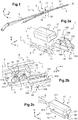
figure 1 est une vue en perspective montrant un système d'essuyage, - la
figure 2a est une vue de dessus éclatée d'un premier mode de réalisation d'un dispositif de connexion sur un segment terminal d'un bras d'essuie-glace du système d'essuyage de lafigure 1 , - la
figure 2b est une vue de dessous éclatée du dispositif de connexion et du segment terminal du bras d'essuie-glace de lafigure 2a , - la
figure 2c est une vue en perspective du dispositif de connexion desfigures 2a et 2b assemblé sur le segment terminal du bras d'essuie-glace, - la
figure 2d montre un exemple d'axe transversal porté par le segment terminal d'un bras d'essuie-glace, - la
figure 2e est une vue de dessous montrant un capot du dispositif de connexion assemblé au segment terminal du bras d'essuie-glace desfigures 2a à 2c , - la
figure 2f est une vue de côté de lafigure 2e , - la
figure 2g est une première vue en perspective montrant l'intérieur du capot selon le premier mode de réalisation, - la
figure 2h est une deuxième vue en perspective montrant l'intérieur du capot selon le premier mode de réalisation, - la
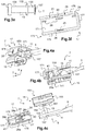
figure 3a montre un deuxième mode de réalisation d'un dispositif de connexion sur un segment terminal d'un bras d'essuie-glace du système d'essuyage de lafigure 1 , - la
figure 3b est une première vue éclatée du dispositif de connexion et du segment terminal du bras d'essuie-glace de lafigure 3a , - la
figure 3c est une deuxième vue éclatée du dispositif de connexion et du segment terminal du bras d'essuie-glace de lafigure 3a , - la
figure 3d est une vue éclatée montrant le segment terminal du bras d'essuie-glace et un connecteur du dispositif de connexion selon le deuxième mode de réalisation avant assemblage au capot, - la
figure 3e montre un axe transversal porté par le segment terminal du bras d'essuie-glace desfigures 3a à 3d , - la
figure 3f est une vue de dessous en perspective du capot selon le deuxième mode de réalisation, - la
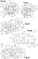
figure 4a montre un troisième mode de réalisation d'un dispositif de connexion sur un segment terminal d'un bras d'essuie-glace du système d'essuyage de lafigure 1 , - la
figure 4b est une vue en coupe de lafigure 4a , - la
figure 4c est une vue éclatée du dispositif de connexion et du segment terminal du bras d'essuie-glace selon le troisième mode de réalisation, - la
figure 4d est une première vue en perspective montrant le dispositif de connexion selon le troisième mode de réalisation assemblé à l'axe transversal, - la
figure 4e est une deuxième vue en perspective montrant le dispositif de connexion selon le troisième mode de réalisation assemblé à l'axe transversal, - la
figure 4f est une vue en perspective du capot du dispositif de connexion selon le troisième mode de réalisation, - la
figure 4g est une vue en coupe du capot selon le troisième mode de réalisation, et - la
figure 4h est une vue de dessous du capot selon le troisième mode de réalisation.
- the
figure 1 is a perspective view showing a wiping system, - the
figure 2a is an exploded top view of a first embodiment of a connection device on a terminal segment of a wiper arm of the wiper system of thefigure 1 , - the
figure 2b is an exploded bottom view of the connection device and of the terminal segment of the wiper arm of thefigure 2a , - the
figure 2c is a perspective view of the device for connecting theFigures 2a and 2b assembled on the terminal segment of the wiper arm, - the
figure 2d shows an example of a transverse axis carried by the terminal segment of a wiper arm, - the
figure 2e is a bottom view showing a cover of the connection device assembled to the terminal segment of the wiper arm of theFigures 2a to 2c , - the
figure 2f is a side view of thefigure 2e , - the
figure 2g is a first perspective view showing the interior of the cover according to the first embodiment, - the
figure 2h is a second perspective view showing the interior of the cover according to the first embodiment, - the
figure 3a shows a second embodiment of a connection device on an end segment of a wiper arm of the wiper system of thefigure 1 , - the
figure 3b is a first exploded view of the connection device and of the terminal segment of the wiper arm of thefigure 3a , - the
figure 3c is a second exploded view of the connection device and of the terminal segment of the wiper arm of thefigure 3a , - the
3d figure is an exploded view showing the end segment of the wiper arm and a connector of the connection device according to the second embodiment before assembly to the cover, - the
figure 3e shows a transverse axis carried by the terminal segment of the wiper arm of thefigures 3a to 3d , - the
figure 3f is a bottom perspective view of the cover according to the second embodiment, - the
figure 4a shows a third embodiment of a connection device on a terminal segment of a wiper arm of the wiper system of thefigure 1 , - the
figure 4b is a sectional view of thefigure 4a , - the
figure 4c is an exploded view of the connection device and of the terminal segment of the wiper arm according to the third embodiment, - the
figure 4d is a first perspective view showing the connection device according to the third embodiment assembled to the transverse axis, - the
figure 4e is a second perspective view showing the connection device according to the third embodiment assembled to the transverse axis, - the
figure 4f is a perspective view of the cover of the connection device according to the third embodiment, - the
figure 4g is a sectional view of the cover according to the third embodiment, and - the
figure 4h is a bottom view of the cover according to the third embodiment.
Sur ces figures, les éléments identiques ou similaires sont identifiés par les mêmes numéros de référence.In these figures, identical or similar elements are identified by the same reference numbers.
Les réalisations suivantes sont des exemples. Bien que la description se réfère à un ou plusieurs modes de réalisation, ceci ne signifie pas nécessairement que chaque référence concerne le même mode de réalisation, ou que les caractéristiques s'appliquent uniquement à un seul mode de réalisation. De simples caractéristiques de différents modes de réalisation peuvent également être combinées ou interchangées pour fournir d'autres réalisations.The following embodiments are examples. Although the description refers to one or more embodiments, this does not necessarily mean that each reference relates to the same embodiment, or that the characteristics apply only to a single embodiment. Simple features of different embodiments can also be combined or interchanged to provide other embodiments.
Dans la description, on peut indexer certains éléments, comme par exemple premier élément ou deuxième élément. Dans ce cas, il s'agit d'un simple indexage pour différencier et dénommer des éléments proches mais non identiques. Cette indexation n'implique pas une priorité d'un élément par rapport à un autre et on peut aisément interchanger de telles dénominations sans sortir du cadre de la présente description. Cette indexation n'implique pas non plus un ordre dans le temps.In the description, it is possible to index certain elements, such as for example first element or second element. In this case, it is a simple indexing to differentiate and name similar but not identical elements. This indexing does not imply a priority of an element over another and one can easily interchange such names without departing from the scope of this description. This indexing does not imply an order in time either.
On a représenté sur la
- au moins un balai d'essuie-
glace 3 destiné à être fixé sur un bras d'essuie-glace 5, et - un dispositif de connexion 7 destiné à permettre l'assemblage du balai d'essuie-
glace 3 au bras d'essuie-glace 5.
- at least one
wiper blade 3 intended to be fixed to awiper arm 5, and - a
connection device 7 intended to allow the assembly of thewiper blade 3 to thewiper arm 5.
Le système d'essuyage 1 peut comprendre ou non le bras d'essuie-glace 5.The
Le balai d'essuie-glace 3 s'étend longitudinalement selon une direction X.The
Le balai d'essuie-glace 3 comporte notamment un déflecteur 31 (ou «spoiler» en anglais) et une lame d'essuyage 33. Le déflecteur 31 et la lame d'essuyage 33 sont en matériau souple.The
Le bras d'essuie-glace 5 s'étend longitudinalement selon une direction L.The
Dans la suite de la description, on adoptera à titre non limitatif des directions longitudinale, verticale et transversale indiquées sur la
Le bras d'essuie-glace 5 comporte un segment terminal 9, mieux visible sur les
Le segment terminal 9 présente une extrémité longitudinale 11. L'extrémité longitudinale 11 porte un axe transversal 13 configuré pour définir un axe de pivotement du balai d'essuie-glace 3 (non visible sur les
Le dispositif de connexion 7 (voir
Le connecteur 15 (
Le capot 17 est configuré pour coopérer avec le connecteur 15 de manière à fixer le balai d'essuie-glace 3 au bras d'essuie-glace 5. Le capot 17 permet notamment le verrouillage de l'ensemble.The
À l'état assemblé du dispositif de fixation 7 sur le segment terminal 9 du bras d'essuie-glace 5, l'axe transversal 13 (visible sur les
Un dispositif de connexion 7 peut comprendre différents types de connecteurs 15 et de capots 17. Les différences entre plusieurs modes de réalisation du connecteur 15 et du capot 17 sont explicitées par la suite.A
En référence aux
L'axe transversal comporte par exemple un épaulement 131 visible sur la
L'épaulement 131 sert ainsi de surface d'appui à l'extrémité longitudinale 11 du bras d'essuie-glace 5 à l'état assemblé de l'axe transversal 13 et de l'extrémité longitudinale 11 (voir
En se référant de nouveau à la
Bien entendu, la forme de l'axe transversal 13, en particulier du deuxième tronçon 135, est complémentaire à la forme d'un orifice (non visible) pratiqué sur l'extrémité longitudinale 11 du segment terminal 9 du bras d'essuie-glace 5 (voir
En référence aux
Le connecteur 15 est par exemple directement relié au bras d'essuie-glace 5. De même, le connecteur 15 peut être directement fixé au balai d'essuie-glace 3.The
Le connecteur 15 présente par exemple une forme d'extension principale longitudinale.The
Selon le premier mode de réalisation illustré sur les
Le connecteur 15 présente une première partie 151 ou partie de liaison au balai d'essuie-glace 3, configurée pour être reliée au balai d'essuie-glace 3 (non visible sur les
La première partie 151 du connecteur 15 présente par exemple une forme d'étrier allongé suivant la direction longitudinale L et destiné à enserrer le balai d'essuie-glace 3, non représenté sur les
La deuxième partie 153 du connecteur 15 comporte, dans cet exemple illustré sur les
Les parois latérales 157 présentent des moyens d'assemblage à l'axe transversal 13. Selon l'exemple illustré, un orifice 159 pour le passage de l'axe transversal 13 est ménagé dans chaque paroi latérale 157. Les orifices 159 forment les moyens d'assemblage à l'axe transversal 13.The
Plus précisément, les orifices 159 sont de forme complémentaire à la forme de l'axe transversal 13, en particulier du premier tronçon 133. Les orifices 159 sont de section circulaire selon l'exemple illustré.More specifically, the
Les brides ou parois latérales 157 sont reçues dans l'espace interne délimité par le capot 17 à l'état assemblé du dispositif de connexion 7 (voir
En référence aux
Le capot 17 est destiné à se fixer sur le connecteur 15 du côté opposé à la lame d'essuyage 33 du balai d'essuie-glace 3, en se référant également à la
Le capot 17 peut être monté sur le segment terminal 9 du bras d'essuie-glace 5 dont l'axe transversal 13 est monté dans le connecteur 15.The
Le capot 17 présente une forme longitudinale. La direction longitudinale L du trièdre correspond à la direction principale du capot 17.The
Selon le premier mode de réalisation illustré sur les
Par ailleurs, le capot 17 présente par exemple une forme ouverte, c'est-à-dire qui n'est pas fermée de tous les côtés.Furthermore, the
Selon le premier mode de réalisation illustré sur les
La partie supérieure 171 est configurée pour recouvrir le segment terminal 9 du bras d'essuie-glace 5 portant l'axe transversal 13 à l'état assemblé du capot 17 au bras d'essuie-glace 5 (voir
La partie supérieure est par exemple formée par une paroi supérieure 171 du capot 17, qui peut être de forme sensiblement rectangulaire, c'est-à-dire de forme rectangulaire ou équivalente ou similaire.The upper part is for example formed by an
Par ailleurs, selon ce premier mode de réalisation illustré, le capot 17 comporte également deux parois latérales 175 opposées reliées par la paroi supérieure 171. Autrement dit, les parois latérales 175 s'étendent depuis la paroi supérieure 171. À l'état assemblé du capot 17 au bras d'essuie-glace 5, les parois latérales 175 s'étendent en direction du segment terminal 9 du bras d'essuie-glace 5.Furthermore, according to this first illustrated embodiment, the
Le capot 17 comporte encore selon le premier mode de réalisation illustré, une paroi d'extrémité 177 reliée à la paroi supérieure 171 et aux parois latérales 175. La paroi d'extrémité 177 s'étend ici selon un plan parallèle au plan V, T et les parois latérales 175 s'étendent ici selon un plan parallèle au plan L, V.The
On entend par « partie inférieure » 173, aussi bien une paroi inférieure agencée en regard de la partie supérieure ici de la paroi supérieure 171, qu'un ou plusieurs bords inférieurs du capot 17, notamment des parois latérales 175 et/ou d'extrémité 177 du capot 17. En variante ou en complément, la partie inférieure 173 peut comporter une portion des parois latérales 175 et/ou d'extrémité 177 du capot 17 qui se trouve du côté opposé à la paroi supérieure 171.The term “lower part” 173 means both a lower wall arranged opposite the upper part here of the
Dans l'exemple illustré, aucune paroi n'est agencée en regard de la paroi supérieure 171. La partie inférieure 173 est formée par les bords inférieurs ainsi que les portions inférieures des parois latérales 175 et éventuellement de la paroi d'extrémité 177.In the example illustrated, no wall is arranged opposite the
De plus, la partie inférieure 173 du capot 17 comporte au moins un moyen de maintien 19 réalisé d'une seule pièce avec le capot 17.In addition, the
Un exemple de moyens de maintien 19 selon le premier mode de réalisation est représenté sur les
En référence aux
On entend par « moyen » de maintien, tout élément, ou dispositif ou organe participant au maintien du segment terminal 9 du bras d'essuie-glace 5 dans le capot 17, à l'état assemblé. On peut citer à titre d'exemple non limitatif, et de façon non exhaustive, un ou plusieurs reliefs, crochets, une ou plusieurs protubérances, languettes, pattes, nervures ou encore toute autre déformation du capot 17.“Holding” means means any element, or device or member participating in maintaining the
Selon le premier mode de réalisation illustré, deux moyens de maintien 19 sont prévus sur la partie inférieure 173 du capot 17. Ces moyens de maintien 19 peuvent comporter au moins un élément ou organe d'encliquetage.According to the first illustrated embodiment, two holding means 19 are provided on the
Chaque moyen de maintien 19 peut comporter au moins un relief 21. Le ou chaque relief 21 est formé sur la partie inférieure 173 du capot 17, à savoir dans cet exemple formé sur la portion inférieure d'une paroi latérale 175 du capot 17. Le ou chaque relief 21 est venu de matière avec le capot 17.Each holding means 19 may include at least one
En particulier, le capot 17 peut comporter au moins deux reliefs 21 distincts. Les deux reliefs 21 sont avantageusement agencés sur la même paroi latérale 175. Bien entendu, un seul relief 21 ou au contraire plus de deux reliefs 21 peuvent être envisagés.In particular, the
Chaque relief 21 fait saille sur la paroi latérale 175, plus précisément sur la portion inférieure ou le bas de la paroi latérale 175, en s'étendant depuis la paroi latérale 175 vers l'intérieur du capot 17.Each
Le ou chaque relief 21 s'étend longitudinalement selon la direction longitudinale L du capot 17.The or each
Il s'agit en particulier dans cet exemple de reliefs d'encliquetage 21 configurés pour bloquer le retrait du segment terminal 9 du bras d'essuie-glace 5 après assemblage au capot 17. Ces reliefs d'encliquetage 21 sont avantageusement également conformés de manière à faciliter l'assemblage du segment terminal 9 du bras d'essuie-glace 5 avec le capot 17.In this example, it is in particular snap-on
Pour ce faire, chaque relief 21 comporte une face oblique 211 et une face d'arrêt 213.To do this, each
La face oblique 211 est oblique ou inclinée par rapport à la partie inférieure 173 du capot 17. Dans cet exemple, la face oblique 211 est inclinée par rapport au plan formé par la paroi latérale 175 portant le relief 21. Il s'agit ici d'un plan parallèle au plan L, T.The
La face oblique 211 est configurée pour être en contact avec le segment terminal 9 du bras d'essuie-glace 5 lors de l'assemblage du segment terminal 9 avec le capot 17. Plus précisément, la face oblique 211 est la première face de chaque relief 21 à être en contact avec l'extrémité longitudinale 11 du segment terminal 9 du bras d'essuie-glace 5. Cette face oblique 211 fait office de bord d'attaque.The
Cette face oblique 211 est configurée de manière à faciliter l'introduction du bras d'essuie-glace 5, c'est-à-dire le mouvement de coulissement ou translation verticale. Pour ce faire, on prévoit par exemple que la face oblique 211 forme une pente ascendante dans le sens d'introduction du segment terminal 9 du bras d'essuie-glace 5 dans le capot 17.This
La face d'arrêt 213, mieux visible sur la
Selon l'exemple de réalisation particulier illustré sur les
La base du relief 21 coïncide avec la face interne de la paroi latérale 175 du capot 17 portant le relief 21. On entend par « face interne » d'une paroi latérale 175 du capot 17, la face agencée du côté du connecteur 15 et étant en regard d'une face latérale 157 du connecteur 15 à l'état assemblé du dispositif de connexion 7.The base of the
Cette base du relief 21 délimite dans l'exemple illustré une forme sensiblement rectangulaire s'étendant longitudinalement selon la direction L. Autrement dit, la base du relief 21 peut être de forme rectangulaire ou similaire.This base of the
Les faces latérales 215 du relief 21 sont respectivement de forme sensiblement triangulaire. Autrement dit, les faces latérales 215 sont de forme triangulaire ou similaire. Ces faces latérales 215 joignent la base, la face d'arrêt 213 et la face oblique 211.The lateral faces 215 of the
Ainsi, lors de l'assemblage du capot 17 au bras d'essuie-glace 5 et au connecteur 15 recevant l'axe transversal 13 du bras d'essuie-glace 5, l'extrémité longitudinale 11 coulisse sur la face oblique 211 jusqu'à venir en appui contre le rebord formé par la face d'arrêt 213, à la fin de la course d'introduction du segment terminal 11 du bras d'essuie-glace 5 dans le capot 17. Une fois la face inférieure de l'extrémité longitudinale 11 en appui sur la face d'arrêt 213, ceci contribue à bloquer le bras d'essuie-glace 5 en translation selon l'axe vertical V.Thus, during assembly of the
Selon une variante de réalisation, le ou les reliefs d'encliquetage 21 peuvent avoir une fonction de guidage du segment terminal 9 du bras d'essuie-glace 5, lors de l'assemblage du segment terminal 9 dans le capot 17.According to an alternative embodiment, the latching relief or
Par ailleurs, on peut prévoir que le capot 17 comporte de plus un guide de l'extrémité 137 de l'axe transversal 13 lors de l'introduction du segment terminal 9 du bras d'essuie-glace 5 dans le capot 17. Ce guide est par exemple réalisé sous la forme d'un évidement 22 sur la paroi latérale 175 présentant les reliefs 21. Cet évidement 22 est visible sur les
L'évidement 22 est de forme adaptée pour le guidage de l'extrémité 137 selon un mouvement de coulissement vertical, et est donc complémentaire à la forme de l'extrémité 137. L'évidement 22 présente par exemple une forme sensiblement en « U », comme cela est visible sur la
La base du « U » se trouve dans cet exemple à proximité de la paroi supérieure 171 du capot 17 et les extrémités des branches du « U » de part et d'autre de la base, se trouvent à proximité des reliefs 21.The base of the "U" is in this example near the
En outre, comme dit précédemment, le capot 17 permet notamment le verrouillage de l'ensemble. À cet effet, le capot 17 comporte au moins un moyen de fixation 23 (voir
Le moyen de fixation 23 peut permettre la fixation / le maintien de l'axe transversal par coopération de forme avec l'axe transversal 13.The fixing means 23 can allow the fixing / the maintenance of the transverse axis by form cooperation with the
Selon le premier mode de réalisation illustré sur les
L'orifice 25 est prévu sur la paroi latérale 175 du capot 17 opposée à la paroi latérale 175 portant le ou les moyens de maintien 19. Cet orifice 25 est donc agencé du côté opposé aux deux reliefs 21 précédemment décrits.The
De façon complémentaire, le moyen de fixation 23 peut comporter de plus une pente 26.In addition, the fastening means 23 can also have a
La pente 26 est formée sur la face interne de la paroi latérale 175 du capot 17 présentant l'orifice 25.The
Cette pente 26 est agencée de manière à débuter du bord inférieur de la paroi latérale 175 du capot 17 présentant l'orifice 25, pour se terminer en formant une portion du contour de l'orifice 25.This
La pente 26 est inclinée par rapport au plan général défini par la paroi latérale 175 du capot 17 présentant l'orifice 25. À titre d'exemple non limitatif, la pente 26 est inclinée par rapport au plan défini par cette paroi latérale 175 d'un angle α de l'ordre de 10° à 30°. En particulier, l'angle α peut être de façon non limitative de l'ordre de 15°.The
De plus, afin de faciliter l'insertion de l'axe transversal 13 dans l'orifice 25 lors de l'assemblage du segment terminal 9 du bras d'essuie-glace 5 au capot 17, la pente 26 est ascendante depuis le bord inférieur de la paroi latérale 175 jusqu'à l'orifice 25.In addition, in order to facilitate the insertion of the
À l'état assemblé, c'est donc l'extrémité libre du premier tronçon 133 de l'axe transversal 13 qui est bloquée dans l'orifice 25. Une fois l'extrémité libre du premier tronçon 133 de l'axe transversal 13 engagée dans l'orifice 25 associé, cela permet de limiter le déplacement longitudinal et vertical relatif entre le capot 17 et le segment terminal 9 du bras d'essuie-glace 5, et donc d'empêcher l'arrachement longitudinal ou vertical.In the assembled state, it is therefore the free end of the
Le moyen de fixation 23 peut comporter de plus au moins deux protubérances 27 formées sur la partie supérieure 171 du capot 17. Plus précisément, les protubérances 27 sont formées sur la face interne de la paroi supérieure 171 formant la partie supérieure. On entend par « face interne », la face de la paroi supérieure 171 destinée à être agencée en regard du connecteur 15 à l'état assemblé du dispositif de connexion 7.The fixing means 23 may further comprise at least two
Ces protubérances 27 s'étendent vers l'intérieur du capot 17. L'axe transversal 13 du segment terminal 9 du bras d'essuie-glace 5 est configuré pour s'engager entre les deux protubérances 27 lors de l'assemblage avec le capot 17, comme cela est mieux visible sur la
En particulier, les protubérances 27 présentent chacune, sensiblement une forme en huit, simplifiée par la suite par forme en « 8 » en utilisant la référence numérique « 8 ». Autrement dit, les protubérances présentent une forme en « 8 » ou équivalente, c'est-à-dire se rapprochant de la forme en « 8 ». Bien entendu, cette forme en « 8 » n'est pas limitative et toute autre forme peut être envisagée.In particular, the
Le bras d'essuie-glace 5 fixé au connecteur 15 et au capot 17 par l'axe transversal 13 est donc maintenu à l'arrachement suivant la direction verticale V par le capot 17 et notamment les reliefs 21 et le trou borgne 25, et éventuellement les protubérances 27, en l'empêchant de sortir par le bas en référence à la disposition des éléments sur les
En outre, de façon à permettre le verrouillage ou le déverrouillage du capot 17 et du segment terminal 9 du bras d'essuie-glace 5, le capot 17 comporte au moins un élément flexible ou souple. Selon le mode de réalisation décrit, au moins la paroi latérale 175 du capot 17 portant le relief 21 est au moins partiellement flexible et est donc configurée pour se déformer de manière à permettre le verrouillage ou le déverrouillage. Avantageusement, les deux parois latérales 175 opposées sont au moins partiellement flexibles.In addition, so as to allow the locking or unlocking of the
Le capot 17 forme alors un organe de préhension configuré pour se déformer de manière réversible, sous l'action d'un effort extérieur. Pour l'assemblage du capot 17 au bras d'essuie-glace 5, un utilisateur peut pousser le capot 17 selon la direction verticale V de sorte que les reliefs 21 et l'extrémité longitudinale 11 du bras d'essuie-glace 5 coulissent l'un par rapport à l'autre. Au moins la paroi latérale 175 portant les reliefs 21 se déforme du fait de la pente de la face oblique 211 de chaque relief 21. Pour désengager l'extrémité longitudinale 11 des rebords 213 des reliefs 21 formés sur le capot 17, voir
Enfin, le capot 17 peut également comporter au moins une butée 29. Dans l'exemple illustré sur les
Les butées 29 peuvent être réalisées d'une seule pièce avec le capot 17. Ces butées 29 servent à l'ajustement du montage du segment terminal 9 du bras d'essuie-glace 5 dans le capot 17, en se référant plus particulièrement à la
De plus, la hauteur de ces butées 29, c'est-à-dire suivant la direction verticale V, peut être adaptée et être retouchée facilement dans l'outil d'injection. Ceci évite de retoucher toute la face, ici la face interne de la paroi supérieure 171 du capot 17.In addition, the height of these
Les butées 29 sont agencées du côté du capot 17 destiné à recevoir l'extrémité longitudinale 11 du bras d'essuie-glace 5. Autrement dit, les butées 29 sont agencées du même côté que les reliefs 21, mais en étant décalées selon la direction verticale V. Les reliefs 21 sont agencés en bas tandis que les butées 29 sont agencées en haut.The stops 29 are arranged on the side of the
Par ailleurs, selon ce premier mode de réalisation, les moyens de maintien 19 et de fixation 23 sont réalisés d'une seule pièce avec le capot 17 tout en étant prévus dans l'exemple illustré en des endroits distincts du capot 17. On facilite ainsi la réalisation de la pièce et cela améliore le montage et le démontage sur le connecteur 15.Furthermore, according to this first embodiment, the holding means 19 and fixing 23 are made in one piece with the
Un deuxième mode de réalisation est illustré sur les
Selon le deuxième mode de réalisation, le dispositif de connexion 7 (
L'axe transversal 13, mieux visible sur la
De façon similaire au premier mode de réalisation, l'axe transversal 13 présente un premier tronçon 133 configuré pour être assemblé au connecteur 15 (non visible sur la
De plus, selon l'exemple illustré, le collet 132 est situé entre le premier tronçon 133 et le deuxième tronçon 135. Les premier et deuxième tronçons 133 et 135 de l'axe transversal 13, de part et d'autre du collet 132, peuvent être de même diamètre.In addition, according to the example illustrated, the
Le collet 132 présente selon le deuxième mode de réalisation une surface d'appui sur l'extrémité longitudinale 11, du bras d'essuie-glace 5 à l'état assemblé de l'axe transversal 13 et de l'extrémité longitudinale 11, comme cela est visible sur les
Dans l'exemple de la
Le premier tronçon 133 est destiné à être monté dans le connecteur 15, de sorte que le collet 132 et l'embase 136 sont agencés en appui ou butée contre les faces externes des parois latérales 157 du connecteur 15 (voir
De façon similaire au premier mode de réalisation, l'axe transversal 13 peut comporter en outre une extrémité 137 de diamètre supérieur au deuxième tronçon 135, par exemple formée par bouterollage. Le deuxième tronçon 135 est interposé entre le collet 132 et l'extrémité 137.Similarly to the first embodiment, the
En ce qui concerne le connecteur 15, selon ce deuxième mode de réalisation, c'est la deuxième partie 153 ou partie de liaison au bras d'essuie-glace 5 diffère du premier mode de réalisation.As regards the
En particulier, les moyens d'assemblage à l'axe transversal 13 des deux parois latérales 157 ne sont plus réalisés sous forme d'orifice 159, comme dans le premier mode de réalisation mais sous forme d'encoches 159' (voir
En ce qui concerne le capot 17 mieux visible sur la
Selon le deuxième mode de réalisation, le moyen de fixation 23 peut ne plus comporter de protubérances 27 formées sur la paroi supérieure 171 du capot 17, précédemment décrites en référence aux
Le reste de la description en référence au premier mode de réalisation illustré sur les
Un troisième mode de réalisation est illustré sur les
En particulier, selon ce troisième mode de réalisation, c'est le capot 17 qui diffère.In particular, according to this third embodiment, it is the
Le capot 17 est configuré pour un assemblage au connecteur 15 par translation longitudinale, de façon sensiblement parallèle à la direction longitudinale L. On entend par translation de façon sensiblement parallèle, une translation parallèlement à la direction longitudinale L ou selon une direction se rapprochant d'une direction parallèle à la direction longitudinale L.The
À cet effet, le capot 17 peut comprendre un ou plusieurs moyens de guidage du connecteur 15 et/ou du segment terminal 9.To this end, the
De plus, selon ce troisième mode de réalisation, la partie inférieure 173 du capot 17 comporte un moyen de maintien 19 réalisé d'une seule pièce avec le capot 17 et comportant un relief 21' (voir
Bien entendu, en variante, on peut envisager plusieurs reliefs 21'.Of course, as a variant, it is possible to envisage
De façon similaire au premier mode de réalisation, le relief 21' fait saille sur la portion inférieure ou basse de la paroi latérale 175, en s'étendant vers l'intérieur du capot 17.Similarly to the first embodiment, the
Il s'agit en particulier dans cet exemple d'un relief 21' de guidage configuré pour guider le segment terminal 9 du bras d'essuie-glace 5 lors de l'assemblage du segment terminal 9 du bras d'essuie-glace 5 au capot 17. Le relief 21' fait donc office de moyen de guidage du segment terminal 9 du bras d'essuie-glace 5.In this example, this is in particular a guide relief 21 'configured to guide the
Le relief 21' peut présenter une forme similaire à celle des reliefs 21 du premier mode de réalisation.The
De plus, le capot 17 peut comporter au moins une cloison 41 formant butée pour le segment terminal 9 du bras d'essuie-glace 5. Cette cloison 41, mieux visible sur la
Cette cloison 41 s'étend vers l'intérieur du capot 17, en particulier, selon un plan parallèle au plan T, V, de façon sensiblement parallèle à la paroi d'extrémité 177. Autrement dit, la cloison 41 s'étend parallèlement à la paroi d'extrémité 177 ou quasiment parallèlement à la paroi d'extrémité 177.This
En particulier, la cloison 41 et le relief 21' peuvent être formés sans discontinuité de matière.In particular, the
De façon similaire au premier mode de réalisation, le capot 17 comporte un guide de l'extrémité 137 de l'axe transversal 13 lors de l'introduction du segment terminal 9 du bras d'essuie-glace 5 dans le capot 17, par exemple réalisé sous la forme d'un évidement 22' (voir
L'évidement 22' présente par exemple une forme sensiblement en « U ». Autrement dit, l'évidement 22' présente une forme en « U » ou équivalente.The
Contrairement au premier mode de réalisation, la forme du « U » est adaptée pour une translation longitudinale et non plus pour un coulissement vertical. Dans ce cas, les branches du « U » s'étendent longitudinalement suivant la direction longitudinale L. Autrement dit, les branches du « U » s'étendent de façon parallèle ou quasi-parallèle, au relief 21'. La base du « U » est orientée en direction de la paroi d'extrémité 177 du capot 17. L'évidement 22' est situé au-dessus du relief 21'.Unlike the first embodiment, the shape of the "U" is suitable for longitudinal translation and no longer for vertical sliding. In this case, the branches of the "U" extend longitudinally in the longitudinal direction L. In other words, the branches of the "U" extend in parallel or almost parallel, to the relief 21 '. The base of the "U" is oriented towards the
En outre, en se référant de nouveau aux
De façon similaire au premier mode de réalisation, l'orifice 25' est prévu sur la paroi latérale 175 du capot 17 opposée à la paroi latérale 175 portant le relief 21'.Similarly to the first embodiment, the orifice 25 'is provided on the
Cependant, contrairement au premier mode de réalisation, il s'agit d'un orifice 25' traversant et non plus d'un orifice 25 borgne. Comme cela est mieux visible sur la
Selon ce troisième mode de réalisation, on peut également prévoir une pente 26' permettant de guider l'axe transversal 13 jusqu'à l'orifice 25', visible sur la
Cependant, contrairement au premier mode de réalisation la pente 26' est agencée de manière à débuter du bord latéral, et non plus du bord inférieur, de la paroi latérale 175 du capot 17 présentant l'orifice 25', pour se terminer en formant une portion du contour de l'orifice 25'.However, unlike the first embodiment, the
Par ailleurs, la paroi latérale 175 présentant la pente 26' comporte au moins une nervure 43, définie par le rebord de la découpe pour réaliser la pente 26'. Cette nervure 43 assure avantageusement une fonction de moyen de guidage du connecteur 15 à l'assemblage du dispositif de connexion 7. Une paroi latérale 157 du connecteur 15, en particulier le haut de cette paroi latérale 157, peut coulisser sur la nervure 43.Furthermore, the
Par ailleurs, en se référant aux
Au contraire, selon le troisième mode de réalisation illustré, le moyen de fixation 23 peut comporter au moins une paroi de fixation 28a. Dans l'exemple illustré, au moins deux parois de fixation 28a sont prévues. Ces parois de fixation 28a s'étendent depuis la partie supérieure 171 du capot 17 vers l'intérieur du capot 17, plus précisément depuis la face interne de la paroi supérieure 171 formant la partie supérieure du capot 17 selon les modes de réalisation décrits.On the contrary, according to the third illustrated embodiment, the fixing means 23 can comprise at least one fixing
Les parois de fixation 28a s'étendent de façon sensiblement parallèle aux parois latérales 175 du capot 17. Autrement dit, les parois de fixation 28a s'étendent parallèlement ou quasi parallèlement aux parois latérales 175 du capot 17. Les parois de fixation 28a s'étendent dans cet exemple selon un plan parallèle au plan L, V.The fixing
L'une des parois de fixation 28a est agencée en regard de la paroi de latérale 175 du capot 17 sur laquelle l'orifice 25' est prévu. L'autre paroi de fixation 28a est agencée en regard de la paroi de latérale 175 du capot 17 présentant l'évidement 22'. Les deux parois de fixation 28a sont agencées en vis-à-vis l'une de l'autre.One of the fixing
De plus, les parois de fixation 28a présentent respectivement une encoche 281. À l'assemblage du capot 7 au connecteur 5 dans lequel l'axe transversal 13 est monté, cet axe transversal 13 s'engage dans les encoches 281.In addition, the fixing
Les deux encoches 281, l'orifice 25' et l'évidement 22' sont alignés selon la direction transversale T.The two
Par ailleurs, les encoches 281 sont de forme complémentaire à la forme de l'axe transversal 13, en particulier du premier tronçon 133. Les encoches 281 sont de forme sensiblement en « U » selon l'exemple illustré. C'est-à-dire, les encoches 281 sont de forme en « U » ou de forme équivalente ou similaire, se rapprochant du « U ».Furthermore, the
Les parois de fixation 28a font office de parois d'accrochage ou de crochets pour la fixation de l'axe transversal 13.The fixing
On peut prévoir en outre une paroi supplémentaire 28b faisant la jonction entre les deux parois de fixation 28a. La paroi de jonction 28b s'étend en regard de la paroi d'extrémité 177. Cette paroi de jonction 28b s'étend dans cet exemple parallèlement, ou quasiment parallèlement, à la paroi d'extrémité 177.An
L'ensemble des parois de fixation 28a et de jonction 28b présente dans l'exemple illustré une section sensiblement en « U », c'est-à-dire en « U » ou d'une forme se rapprochant au « U », comme cela est mieux visible sur la
Enfin, en se référant de nouveau à la
Pour l'assemblage du capot 17 au bras d'essuie-glace 5, un utilisateur peut faire coulisser le capot 17 de sorte que l'extrémité longitudinale 11 du bras d'essuie-glace 5 coulisse par rapport au relief 21'. Au moins la paroi latérale 175 présentant l'orifice 25' se déforme du fait de la pente ascendante 26' qui mène jusqu'à l'orifice 25'.For the assembly of the
Pour désengager l'extrémité l'axe transversal 13 de l'orifice 25', il suffit, de façon similaire au premier mode de réalisation, d'écarter les deux parois latérales 175 du capot 17 pour déverrouiller l'ensemble. Aucun outil n'est nécessaire ni pour le verrouillage ni pour le déverrouillage.To disengage the end of the
Le capot 17 et les moyens de maintien 19 du segment terminal 9 du bras d'essuie-glace 5, et avantageusement les moyens de fixation 23 de l'axe transversal 13 portés par le capot 17, sont réalisés d'une seule pièce. De plus, les moyens de maintien 19 du segment terminal 9 du bras d'essuie-glace 5, sont distincts des moyens de fixation 23 de l'axe transversal 13.The
On réalise ainsi d'une seule pièce un capot 17 et les moyens nécessaires à l'assemblage de façon simple du dispositif de connexion 7 sur le bras d'essuie-glace 5. Selon les premier et deuxième modes de réalisation, le verrouillage peut se faire de façon simple par encliquetage lors de l'assemblage, sans nécessiter de manipulations supplémentaires compliquées.A
De plus, les moyens de maintien 19 et/ou les moyens de fixation 23 sont avantageusement conformés de manière à empêcher un arrachement du capot 17 et/ou du connecteur 15 et/ou du bras d'essuie-glace 5, selon la direction verticale V.In addition, the holding means 19 and / or the fixing means 23 are advantageously shaped so as to prevent tearing of the
En outre, les moyens de fixation 23 sont configurés pour bloquer longitudinalement le mouvement du connecteur 15 dans lequel l'axe transversal 13 est monté, par rapport au capot 17.In addition, the fixing means 23 are configured to longitudinally block the movement of the
Enfin, les moyens de maintien 19 et/ou les moyens de fixation 23 permettent un verrouillage réversible du dispositif de connexion 7 sur le bras d'essuie-glace 5.Finally, the holding means 19 and / or the fixing means 23 allow reversible locking of the
Claims (16)
- Cap (17) which is configured to be assembled with a terminal segment (9) of a windscreen wiper arm (5) which is configured to be connected to a windscreen wiper (3), said terminal segment (19) having a longitudinal end (11) bearing a transverse pin (13) which is configured to define a pivot axis of the windscreen wiper (3), the cap (17) comprising :- an upper part (171) which is configured to cover the terminal segment (9) of the windscreen wiper arm (5) in the assembled state of the cap (17) on said terminal segment (9),- a lower part (173) opposing the upper part (171), and- at least one fixing means (23) which is configured to cooperate with the transverse pin (13), so as to fix the transverse pin (13) to the cap (17),characterized in that the lower part (173) of the cap (17) comprises at least one support means (19) which is produced integrally with the cap (17) and which is configured to cooperate with the terminal segment (9) of the windscreen wiper arm (5) for the assembly of the cap (17) with the terminal segment (9) of the windscreen wiper arm (5).
- Cap (17) according to the preceding claim, wherein said at least one support means (19) comprises at least one relief (21; 21') formed on the lower part (173) of the cap (17).
- Cap (17) according to the preceding claim, comprising two opposing lateral walls (175) extending from the upper part (171) of the cap (17), and wherein at least one relief (21; 21') is formed on a lower portion of at least one lateral wall (175).
- Cap (17) according to any one of the preceding claims, wherein said at least one support means (19) comprises at least one clipping relief (21) which is configured to block the retraction of the terminal segment (9) of the windscreen wiper arm (5) in the assembled state of the terminal segment (9) on the cap (17).
- Cap (17) according to any one of the preceding claims, wherein said at least one support means (19) comprises at least one guide relief (21; 21') which is configured to guide the terminal segment (9) of the windscreen wiper arm (5) during the assembly of the terminal segment (9) of the windscreen wiper arm (5) with the cap (17).
- Cap (17) according to one of Claims 2 to 5, having a longitudinal shape, wherein said at least one relief (21; 21') extends in the longitudinal direction (L) of the cap (17).
- Cap (17) according to Claim 6, comprising the same relief (21') extending over more than half of the length of the cap (17).
- Cap (17) according to any one of Claims 2 to 6, comprising at least two separate reliefs (21).
- Cap (17) according to any one of Claims 2 to 8, wherein said at least one relief (21; 21') comprises:- a stop face (213) forming an edge, the terminal segment (9) of the windscreen wiper arm (5) being configured to bear thereagainst in the assembled state of said terminal segment (9) on the cap (17).
- Cap (17) according to any one of the preceding claims, wherein said at least one fixing means (23) comprises at least one orifice (25; 25') formed on the cap (17).
- Cap (17) according to Claim 10, wherein the orifice (25) is blind.
- Cap (17) according to Claim 10, wherein the orifice (25') is a through-orifice.
- Cap (17) according to any one of the preceding claims, wherein said at least one fixing means (23) comprises at least two protuberances (27) formed on the upper part (171) of the cap (17).
- Cap (17) according to any one of the preceding claim, wherein said at least one fixing means (23) comprises at least one fixing wall (28a), or even at least two walls, extending from the upper part (171) of the cap (17) to the interior of the cap (17) and respectively having a notch (281), the transverse pin (13) borne by the windscreen wiper arm (5) being configured to be engaged therein.
- Connecting device (7) for the mounting of a windscreen wiper (3) on a windscreen wiper arm (5), the connecting device (7) comprising :- a connector (15) which is configured to be connected to the windscreen wiper (3), on the one hand, and to the windscreen wiper arm (5), on the other hand, and- a cap (17) which is configured to cooperate with the connector (15) so as to fix the windscreen wiper (3) to the windscreen wiper arm (5),characterized in that the cap (17) is according to any one of the preceding claims.
- Windscreen wiping system for a motor vehicle comprising at least one windscreen wiper (3), characterized in that it comprises a connecting device (7) according to the preceding claim.
Applications Claiming Priority (1)
| Application Number | Priority Date | Filing Date | Title |
|---|---|---|---|
| FR1752075A FR3063950B1 (en) | 2017-03-14 | 2017-03-14 | HOOD, CONNECTING DEVICE FOR MOUNTING WIPER BLADE ON WIPER ARM AND CORRESPONDING WIPING SYSTEM |
Publications (2)
| Publication Number | Publication Date |
|---|---|
| EP3375675A1 EP3375675A1 (en) | 2018-09-19 |
| EP3375675B1 true EP3375675B1 (en) | 2020-02-05 |
Family
ID=58993035
Family Applications (1)
| Application Number | Title | Priority Date | Filing Date |
|---|---|---|---|
| EP18161105.4A Active EP3375675B1 (en) | 2017-03-14 | 2018-03-09 | Cap, connecting device for mounting a windscreen wiper on a corresponding windscreen wiper arm and windscreen wiping system |
Country Status (4)
| Country | Link |
|---|---|
| US (1) | US10780863B2 (en) |
| EP (1) | EP3375675B1 (en) |
| CN (1) | CN108569252B (en) |
| FR (1) | FR3063950B1 (en) |
Families Citing this family (1)
| Publication number | Priority date | Publication date | Assignee | Title |
|---|---|---|---|---|
| FR3105768B1 (en) * | 2019-12-27 | 2022-06-17 | Valeo Systemes Dessuyage | Motor vehicle wiper system |
Family Cites Families (17)
| Publication number | Priority date | Publication date | Assignee | Title |
|---|---|---|---|---|
| DE10259480A1 (en) * | 2002-06-28 | 2004-01-15 | Robert Bosch Gmbh | wiper blade |
| DE10259477B4 (en) * | 2002-12-19 | 2020-12-10 | Robert Bosch Gmbh | Prevention arrangement of a wiper device for windows of motor vehicles |
| CN100584673C (en) * | 2005-02-03 | 2010-01-27 | 罗伯特·博世有限公司 | Device for the pivoting connection of a wiper blade to a wiper arm of a windscreen wiper |
| EP2326538B1 (en) * | 2008-09-13 | 2013-03-20 | Robert Bosch GmbH | Connecting device for the articulated connection of a wiper blade to a wiper arm |
| US9168897B2 (en) * | 2009-10-12 | 2015-10-27 | Federal-Mogul S.A. | Windscreen wiper device |
| TWM404153U (en) * | 2010-09-07 | 2011-05-21 | Zhi-Ming Yang | Joining structure applicable for windshield wiper |
| US9889823B2 (en) * | 2010-12-02 | 2018-02-13 | Valeo Systèmes d'Essuyage | Hydraulic connector for a windshield wiper blade having a retractable button |
| DE102011079783A1 (en) * | 2011-07-26 | 2013-01-31 | Robert Bosch Gmbh | Connecting device for articulated connection of a wiper blade with a wiper arm and an adapter |
| US9688251B2 (en) * | 2012-01-20 | 2017-06-27 | Dongguan Hongyi Wiper Co., Ltd. | Wiper connector and bolt-stabilizing sleeve adaptor |
| KR101369629B1 (en) * | 2012-04-06 | 2014-03-04 | 주식회사 캐프 | Wiper device for vehicle |
| DE102012209956A1 (en) * | 2012-06-14 | 2013-12-19 | Robert Bosch Gmbh | Wiper blade adapter system for wiper blade, comprises wiper blade adapter unit with transmission unit, which is provided to release coupling between connecting element and wiper blade adapter unit during disassembly process |
| DE102012210544A1 (en) * | 2012-06-21 | 2013-12-24 | Robert Bosch Gmbh | Wiping adapter device |
| US9555775B2 (en) * | 2013-03-15 | 2017-01-31 | Illinois Tool Works Inc. | Connectors and connector kit for attachment of a windshield wiper blade to multiple types of windshield wiper arms |
| FR3011211B1 (en) * | 2013-09-30 | 2017-01-13 | Valeo Systemes Dessuyage | CONNECTOR OR ADAPTER FOR A WINDSHIELD WINDSCREEN SYSTEM, IN PARTICULAR A MOTOR VEHICLE |
| FR3031712B1 (en) * | 2015-01-16 | 2018-10-12 | Valeo Systemes D'essuyage | ICE WIPER COVER CONFIGURE TO COVER A TERMINAL PART OF A WIPER ARM |
| FR3037901A1 (en) * | 2015-06-29 | 2016-12-30 | Valeo Systemes Dessuyage | ADAPTER FOR CONNECTING A WIPER BLADE TO A TRAINING ARM |
| FR3046762B1 (en) * | 2016-01-15 | 2018-01-26 | Valeo Systemes D'essuyage | END CAP FOR A VEHICLE WIPER BLADE |
-
2017
- 2017-03-14 FR FR1752075A patent/FR3063950B1/en not_active Expired - Fee Related
-
2018
- 2018-03-09 EP EP18161105.4A patent/EP3375675B1/en active Active
- 2018-03-13 US US15/919,598 patent/US10780863B2/en active Active
- 2018-03-14 CN CN201810208315.3A patent/CN108569252B/en active Active
Non-Patent Citations (1)
| Title |
|---|
| None * |
Also Published As
| Publication number | Publication date |
|---|---|
| FR3063950A1 (en) | 2018-09-21 |
| EP3375675A1 (en) | 2018-09-19 |
| FR3063950B1 (en) | 2019-04-19 |
| CN108569252B (en) | 2021-07-27 |
| US20180265046A1 (en) | 2018-09-20 |
| US10780863B2 (en) | 2020-09-22 |
| CN108569252A (en) | 2018-09-25 |
Similar Documents
| Publication | Publication Date | Title |
|---|---|---|
| EP1884425B1 (en) | Adapter for fixing a windscreen-wiper blade on an arm | |
| EP3168093B1 (en) | Adapter for a motor vehicle windscreen wiper | |
| EP3135547B1 (en) | Support element, wiper blade and windscreen wiper of a motor vehicle | |
| EP3165416B1 (en) | Adapter for a motor vehicle windscreen wiper | |
| EP3231673A1 (en) | System for wiping a windscreen of a vehicle | |
| EP3045357B1 (en) | Cap for a windscreen wiper for covering an end portion of a wiper arm | |
| EP2965958B1 (en) | Assembly comprising a mechanical connector and a cannula for a vehicle windscreen-wiper blade | |
| EP3375675B1 (en) | Cap, connecting device for mounting a windscreen wiper on a corresponding windscreen wiper arm and windscreen wiping system | |
| EP3081439B1 (en) | End cap for a wiper | |
| EP2965957B1 (en) | Pivot link for a vehicle wiper blade | |
| EP2803544B1 (en) | Assembly for producing a windscreen-wiper system for a motor vehicle and connection device including such an assembly | |
| EP3012163B1 (en) | Device for spraying windscreen washer liquid for a wiper of a vehicle windscreen wiping system | |
| EP3902710B1 (en) | Adapter for motor vehicle wiper blade mount | |
| EP3366531B1 (en) | Adaptable end cap for a wiper blade | |
| EP4028292A1 (en) | Crank pin, ball joint and corresponding wiper actuating linkage system and method for the assembly thereof | |
| FR2731191A1 (en) | Windscreen wiper for motor vehicle | |
| EP3112228B1 (en) | Member for a system for connecting a blade to a wiper arm | |
| EP1470942B1 (en) | Arrangement to fasten a support of a sun curtain | |
| EP3434536B1 (en) | Attachment device for a windscreen wiper linkage system | |
| WO2022171832A1 (en) | Adapter for a wiping system | |
| EP3402703B1 (en) | Adapter for connecting a wiper blade to a drive arm | |
| WO2023030973A1 (en) | Adapter for a wiping system | |
| WO2020239709A1 (en) | Cover for a drive arm | |
| WO2023208726A1 (en) | Wiper system connection assembly | |
| WO2023110974A1 (en) | End cap and windscreen-wiper blade for a motor vehicle |
Legal Events
| Date | Code | Title | Description |
|---|---|---|---|
| PUAI | Public reference made under article 153(3) epc to a published international application that has entered the european phase |
Free format text: ORIGINAL CODE: 0009012 |
|
| STAA | Information on the status of an ep patent application or granted ep patent |
Free format text: STATUS: REQUEST FOR EXAMINATION WAS MADE |
|
| 17P | Request for examination filed |
Effective date: 20180309 |
|
| AK | Designated contracting states |
Kind code of ref document: A1 Designated state(s): AL AT BE BG CH CY CZ DE DK EE ES FI FR GB GR HR HU IE IS IT LI LT LU LV MC MK MT NL NO PL PT RO RS SE SI SK SM TR |
|
| AX | Request for extension of the european patent |
Extension state: BA ME |
|
| GRAP | Despatch of communication of intention to grant a patent |
Free format text: ORIGINAL CODE: EPIDOSNIGR1 |
|
| STAA | Information on the status of an ep patent application or granted ep patent |
Free format text: STATUS: GRANT OF PATENT IS INTENDED |
|
| RIC1 | Information provided on ipc code assigned before grant |
Ipc: B60S 1/40 20060101AFI20190814BHEP |
|
| INTG | Intention to grant announced |
Effective date: 20190830 |
|
| GRAS | Grant fee paid |
Free format text: ORIGINAL CODE: EPIDOSNIGR3 |
|
| GRAA | (expected) grant |
Free format text: ORIGINAL CODE: 0009210 |
|
| STAA | Information on the status of an ep patent application or granted ep patent |
Free format text: STATUS: THE PATENT HAS BEEN GRANTED |
|
| AK | Designated contracting states |
Kind code of ref document: B1 Designated state(s): AL AT BE BG CH CY CZ DE DK EE ES FI FR GB GR HR HU IE IS IT LI LT LU LV MC MK MT NL NO PL PT RO RS SE SI SK SM TR |
|
| REG | Reference to a national code |
Ref country code: GB Ref legal event code: FG4D Free format text: NOT ENGLISH |
|
| REG | Reference to a national code |
Ref country code: AT Ref legal event code: REF Ref document number: 1229687 Country of ref document: AT Kind code of ref document: T Effective date: 20200215 |
|
| REG | Reference to a national code |
Ref country code: DE Ref legal event code: R096 Ref document number: 602018002277 Country of ref document: DE |
|
| REG | Reference to a national code |
Ref country code: IE Ref legal event code: FG4D Free format text: LANGUAGE OF EP DOCUMENT: FRENCH |
|
| REG | Reference to a national code |
Ref country code: CH Ref legal event code: EP |
|
| PGFP | Annual fee paid to national office [announced via postgrant information from national office to epo] |
Ref country code: BE Payment date: 20200330 Year of fee payment: 3 |
|
| REG | Reference to a national code |
Ref country code: NL Ref legal event code: MP Effective date: 20200205 |
|
| PG25 | Lapsed in a contracting state [announced via postgrant information from national office to epo] |
Ref country code: NO Free format text: LAPSE BECAUSE OF FAILURE TO SUBMIT A TRANSLATION OF THE DESCRIPTION OR TO PAY THE FEE WITHIN THE PRESCRIBED TIME-LIMIT Effective date: 20200505 Ref country code: RS Free format text: LAPSE BECAUSE OF FAILURE TO SUBMIT A TRANSLATION OF THE DESCRIPTION OR TO PAY THE FEE WITHIN THE PRESCRIBED TIME-LIMIT Effective date: 20200205 Ref country code: FI Free format text: LAPSE BECAUSE OF FAILURE TO SUBMIT A TRANSLATION OF THE DESCRIPTION OR TO PAY THE FEE WITHIN THE PRESCRIBED TIME-LIMIT Effective date: 20200205 Ref country code: PT Free format text: LAPSE BECAUSE OF FAILURE TO SUBMIT A TRANSLATION OF THE DESCRIPTION OR TO PAY THE FEE WITHIN THE PRESCRIBED TIME-LIMIT Effective date: 20200628 |
|
| REG | Reference to a national code |
Ref country code: LT Ref legal event code: MG4D |
|
| PG25 | Lapsed in a contracting state [announced via postgrant information from national office to epo] |
Ref country code: SE Free format text: LAPSE BECAUSE OF FAILURE TO SUBMIT A TRANSLATION OF THE DESCRIPTION OR TO PAY THE FEE WITHIN THE PRESCRIBED TIME-LIMIT Effective date: 20200205 Ref country code: LV Free format text: LAPSE BECAUSE OF FAILURE TO SUBMIT A TRANSLATION OF THE DESCRIPTION OR TO PAY THE FEE WITHIN THE PRESCRIBED TIME-LIMIT Effective date: 20200205 Ref country code: HR Free format text: LAPSE BECAUSE OF FAILURE TO SUBMIT A TRANSLATION OF THE DESCRIPTION OR TO PAY THE FEE WITHIN THE PRESCRIBED TIME-LIMIT Effective date: 20200205 Ref country code: BG Free format text: LAPSE BECAUSE OF FAILURE TO SUBMIT A TRANSLATION OF THE DESCRIPTION OR TO PAY THE FEE WITHIN THE PRESCRIBED TIME-LIMIT Effective date: 20200505 Ref country code: IS Free format text: LAPSE BECAUSE OF FAILURE TO SUBMIT A TRANSLATION OF THE DESCRIPTION OR TO PAY THE FEE WITHIN THE PRESCRIBED TIME-LIMIT Effective date: 20200605 Ref country code: GR Free format text: LAPSE BECAUSE OF FAILURE TO SUBMIT A TRANSLATION OF THE DESCRIPTION OR TO PAY THE FEE WITHIN THE PRESCRIBED TIME-LIMIT Effective date: 20200506 |
|
| PG25 | Lapsed in a contracting state [announced via postgrant information from national office to epo] |
Ref country code: NL Free format text: LAPSE BECAUSE OF FAILURE TO SUBMIT A TRANSLATION OF THE DESCRIPTION OR TO PAY THE FEE WITHIN THE PRESCRIBED TIME-LIMIT Effective date: 20200205 |
|
| PG25 | Lapsed in a contracting state [announced via postgrant information from national office to epo] |
Ref country code: RO Free format text: LAPSE BECAUSE OF FAILURE TO SUBMIT A TRANSLATION OF THE DESCRIPTION OR TO PAY THE FEE WITHIN THE PRESCRIBED TIME-LIMIT Effective date: 20200205 Ref country code: CZ Free format text: LAPSE BECAUSE OF FAILURE TO SUBMIT A TRANSLATION OF THE DESCRIPTION OR TO PAY THE FEE WITHIN THE PRESCRIBED TIME-LIMIT Effective date: 20200205 Ref country code: SK Free format text: LAPSE BECAUSE OF FAILURE TO SUBMIT A TRANSLATION OF THE DESCRIPTION OR TO PAY THE FEE WITHIN THE PRESCRIBED TIME-LIMIT Effective date: 20200205 Ref country code: LT Free format text: LAPSE BECAUSE OF FAILURE TO SUBMIT A TRANSLATION OF THE DESCRIPTION OR TO PAY THE FEE WITHIN THE PRESCRIBED TIME-LIMIT Effective date: 20200205 Ref country code: DK Free format text: LAPSE BECAUSE OF FAILURE TO SUBMIT A TRANSLATION OF THE DESCRIPTION OR TO PAY THE FEE WITHIN THE PRESCRIBED TIME-LIMIT Effective date: 20200205 Ref country code: ES Free format text: LAPSE BECAUSE OF FAILURE TO SUBMIT A TRANSLATION OF THE DESCRIPTION OR TO PAY THE FEE WITHIN THE PRESCRIBED TIME-LIMIT Effective date: 20200205 Ref country code: EE Free format text: LAPSE BECAUSE OF FAILURE TO SUBMIT A TRANSLATION OF THE DESCRIPTION OR TO PAY THE FEE WITHIN THE PRESCRIBED TIME-LIMIT Effective date: 20200205 Ref country code: SM Free format text: LAPSE BECAUSE OF FAILURE TO SUBMIT A TRANSLATION OF THE DESCRIPTION OR TO PAY THE FEE WITHIN THE PRESCRIBED TIME-LIMIT Effective date: 20200205 |
|
| REG | Reference to a national code |
Ref country code: DE Ref legal event code: R097 Ref document number: 602018002277 Country of ref document: DE |
|
| REG | Reference to a national code |
Ref country code: AT Ref legal event code: MK05 Ref document number: 1229687 Country of ref document: AT Kind code of ref document: T Effective date: 20200205 |
|
| PG25 | Lapsed in a contracting state [announced via postgrant information from national office to epo] |
Ref country code: MC Free format text: LAPSE BECAUSE OF FAILURE TO SUBMIT A TRANSLATION OF THE DESCRIPTION OR TO PAY THE FEE WITHIN THE PRESCRIBED TIME-LIMIT Effective date: 20200205 |
|
| PLBE | No opposition filed within time limit |
Free format text: ORIGINAL CODE: 0009261 |
|
| STAA | Information on the status of an ep patent application or granted ep patent |
Free format text: STATUS: NO OPPOSITION FILED WITHIN TIME LIMIT |
|
| PG25 | Lapsed in a contracting state [announced via postgrant information from national office to epo] |
Ref country code: LU Free format text: LAPSE BECAUSE OF NON-PAYMENT OF DUE FEES Effective date: 20200309 |
|
| 26N | No opposition filed |
Effective date: 20201106 |
|
| PG25 | Lapsed in a contracting state [announced via postgrant information from national office to epo] |
Ref country code: AT Free format text: LAPSE BECAUSE OF FAILURE TO SUBMIT A TRANSLATION OF THE DESCRIPTION OR TO PAY THE FEE WITHIN THE PRESCRIBED TIME-LIMIT Effective date: 20200205 Ref country code: IE Free format text: LAPSE BECAUSE OF NON-PAYMENT OF DUE FEES Effective date: 20200309 Ref country code: IT Free format text: LAPSE BECAUSE OF FAILURE TO SUBMIT A TRANSLATION OF THE DESCRIPTION OR TO PAY THE FEE WITHIN THE PRESCRIBED TIME-LIMIT Effective date: 20200205 |
|
| PG25 | Lapsed in a contracting state [announced via postgrant information from national office to epo] |
Ref country code: PL Free format text: LAPSE BECAUSE OF FAILURE TO SUBMIT A TRANSLATION OF THE DESCRIPTION OR TO PAY THE FEE WITHIN THE PRESCRIBED TIME-LIMIT Effective date: 20200205 Ref country code: SI Free format text: LAPSE BECAUSE OF FAILURE TO SUBMIT A TRANSLATION OF THE DESCRIPTION OR TO PAY THE FEE WITHIN THE PRESCRIBED TIME-LIMIT Effective date: 20200205 |
|
| REG | Reference to a national code |
Ref country code: CH Ref legal event code: PL |
|
| REG | Reference to a national code |
Ref country code: BE Ref legal event code: MM Effective date: 20210331 |
|
| PG25 | Lapsed in a contracting state [announced via postgrant information from national office to epo] |
Ref country code: LI Free format text: LAPSE BECAUSE OF NON-PAYMENT OF DUE FEES Effective date: 20210331 Ref country code: CH Free format text: LAPSE BECAUSE OF NON-PAYMENT OF DUE FEES Effective date: 20210331 |
|
| PG25 | Lapsed in a contracting state [announced via postgrant information from national office to epo] |
Ref country code: TR Free format text: LAPSE BECAUSE OF FAILURE TO SUBMIT A TRANSLATION OF THE DESCRIPTION OR TO PAY THE FEE WITHIN THE PRESCRIBED TIME-LIMIT Effective date: 20200205 Ref country code: MT Free format text: LAPSE BECAUSE OF FAILURE TO SUBMIT A TRANSLATION OF THE DESCRIPTION OR TO PAY THE FEE WITHIN THE PRESCRIBED TIME-LIMIT Effective date: 20200205 Ref country code: CY Free format text: LAPSE BECAUSE OF FAILURE TO SUBMIT A TRANSLATION OF THE DESCRIPTION OR TO PAY THE FEE WITHIN THE PRESCRIBED TIME-LIMIT Effective date: 20200205 |
|
| PG25 | Lapsed in a contracting state [announced via postgrant information from national office to epo] |
Ref country code: MK Free format text: LAPSE BECAUSE OF FAILURE TO SUBMIT A TRANSLATION OF THE DESCRIPTION OR TO PAY THE FEE WITHIN THE PRESCRIBED TIME-LIMIT Effective date: 20200205 Ref country code: AL Free format text: LAPSE BECAUSE OF FAILURE TO SUBMIT A TRANSLATION OF THE DESCRIPTION OR TO PAY THE FEE WITHIN THE PRESCRIBED TIME-LIMIT Effective date: 20200205 |
|
| PG25 | Lapsed in a contracting state [announced via postgrant information from national office to epo] |
Ref country code: BE Free format text: LAPSE BECAUSE OF NON-PAYMENT OF DUE FEES Effective date: 20210331 |
|
| GBPC | Gb: european patent ceased through non-payment of renewal fee |
Effective date: 20220309 |
|
| PG25 | Lapsed in a contracting state [announced via postgrant information from national office to epo] |
Ref country code: GB Free format text: LAPSE BECAUSE OF NON-PAYMENT OF DUE FEES Effective date: 20220309 |
|
| PGFP | Annual fee paid to national office [announced via postgrant information from national office to epo] |
Ref country code: FR Payment date: 20230320 Year of fee payment: 6 |
|
| PGFP | Annual fee paid to national office [announced via postgrant information from national office to epo] |
Ref country code: DE Payment date: 20230307 Year of fee payment: 6 |
|
| P01 | Opt-out of the competence of the unified patent court (upc) registered |
Effective date: 20230528 |