EP1470942B1 - Arrangement to fasten a support of a sun curtain - Google Patents
Arrangement to fasten a support of a sun curtain Download PDFInfo
- Publication number
- EP1470942B1 EP1470942B1 EP20040300214 EP04300214A EP1470942B1 EP 1470942 B1 EP1470942 B1 EP 1470942B1 EP 20040300214 EP20040300214 EP 20040300214 EP 04300214 A EP04300214 A EP 04300214A EP 1470942 B1 EP1470942 B1 EP 1470942B1
- Authority
- EP
- European Patent Office
- Prior art keywords
- support
- arrangement
- pin
- wall
- clip
- Prior art date
- Legal status (The legal status is an assumption and is not a legal conclusion. Google has not performed a legal analysis and makes no representation as to the accuracy of the status listed.)
- Expired - Fee Related
Links
Images
Classifications
-
- B—PERFORMING OPERATIONS; TRANSPORTING
- B60—VEHICLES IN GENERAL
- B60J—WINDOWS, WINDSCREENS, NON-FIXED ROOFS, DOORS, OR SIMILAR DEVICES FOR VEHICLES; REMOVABLE EXTERNAL PROTECTIVE COVERINGS SPECIALLY ADAPTED FOR VEHICLES
- B60J1/00—Windows; Windscreens; Accessories therefor
- B60J1/20—Accessories, e.g. wind deflectors, blinds
- B60J1/2011—Blinds; curtains or screens reducing heat or light intensity
- B60J1/2013—Roller blinds
- B60J1/2036—Roller blinds characterised by structural elements
- B60J1/2038—Storage boxes
-
- B—PERFORMING OPERATIONS; TRANSPORTING
- B60—VEHICLES IN GENERAL
- B60J—WINDOWS, WINDSCREENS, NON-FIXED ROOFS, DOORS, OR SIMILAR DEVICES FOR VEHICLES; REMOVABLE EXTERNAL PROTECTIVE COVERINGS SPECIALLY ADAPTED FOR VEHICLES
- B60J1/00—Windows; Windscreens; Accessories therefor
- B60J1/20—Accessories, e.g. wind deflectors, blinds
- B60J1/2011—Blinds; curtains or screens reducing heat or light intensity
- B60J1/2013—Roller blinds
- B60J1/2063—Mounting arrangements for roller blind or its storage box, e.g. integration into beltline or window frame
-
- B—PERFORMING OPERATIONS; TRANSPORTING
- B60—VEHICLES IN GENERAL
- B60J—WINDOWS, WINDSCREENS, NON-FIXED ROOFS, DOORS, OR SIMILAR DEVICES FOR VEHICLES; REMOVABLE EXTERNAL PROTECTIVE COVERINGS SPECIALLY ADAPTED FOR VEHICLES
- B60J1/00—Windows; Windscreens; Accessories therefor
- B60J1/20—Accessories, e.g. wind deflectors, blinds
- B60J1/2011—Blinds; curtains or screens reducing heat or light intensity
- B60J1/2013—Roller blinds
- B60J1/2066—Arrangement of blinds in vehicles
- B60J1/2069—Arrangement of blinds in vehicles of multiple blinds, e.g. more than one blind per window or per actuation system
-
- B—PERFORMING OPERATIONS; TRANSPORTING
- B60—VEHICLES IN GENERAL
- B60J—WINDOWS, WINDSCREENS, NON-FIXED ROOFS, DOORS, OR SIMILAR DEVICES FOR VEHICLES; REMOVABLE EXTERNAL PROTECTIVE COVERINGS SPECIALLY ADAPTED FOR VEHICLES
- B60J1/00—Windows; Windscreens; Accessories therefor
- B60J1/20—Accessories, e.g. wind deflectors, blinds
- B60J1/2011—Blinds; curtains or screens reducing heat or light intensity
- B60J1/2013—Roller blinds
- B60J1/2066—Arrangement of blinds in vehicles
- B60J1/2072—Blinds with inclined or vertical orientation of the winding axis
-
- B—PERFORMING OPERATIONS; TRANSPORTING
- B60—VEHICLES IN GENERAL
- B60J—WINDOWS, WINDSCREENS, NON-FIXED ROOFS, DOORS, OR SIMILAR DEVICES FOR VEHICLES; REMOVABLE EXTERNAL PROTECTIVE COVERINGS SPECIALLY ADAPTED FOR VEHICLES
- B60J1/00—Windows; Windscreens; Accessories therefor
- B60J1/20—Accessories, e.g. wind deflectors, blinds
- B60J1/2011—Blinds; curtains or screens reducing heat or light intensity
- B60J1/2013—Roller blinds
- B60J1/2066—Arrangement of blinds in vehicles
- B60J1/2086—Arrangement of blinds in vehicles specially adapted for openable windows, e.g. side window
Definitions
- the invention relates to an arrangement for attaching a curtain support sun visor.
- the cavity 68 has a shape substantially complementary to the attachment plate 52 and its boss 54.
- arms 88, 90 of the clip 86 may comprise interlocking means (not shown) capable of cooperating with the fixing pin 64, for example by elastic deformation, so as to retain the clip 86 transversely. in mounted position.
Description
L'invention concerne un agencement pour la fixation d'un support de rideau pare-soleil.The invention relates to an arrangement for attaching a curtain support sun visor.
L'invention concerne plus particulièrement un agencement pour la fixation d'un support de rideau pare-soleil sur la paroi interne d'un montant globalement vertical d'une fenêtre latérale de véhicule automobile. du type dans lequel le support est fixé sur le montant de manière que le rideau puisse occuper au moins une position d'occultation, dans laquelle le rideau couvre au moins une partie de la fenêtre, et une position escamotée.The invention relates more particularly to an arrangement for fixing a sun-curtain support on the inner wall of a generally vertical upright of a motor vehicle side window. of the type in which the support is fixed on the upright so that the curtain can occupy at least one occultation position, wherein the curtain covers at least a portion of the window, and a retracted position.
Le document DE 3822378 décrit un agencement pour la fixation d'un support de rideau pare-soleil comme décrit dans le préambule de la revendication 1.DE 3822378 discloses an arrangement for attaching a sun curtain support as described in the preamble of
La présente invention apporte un perfectionnement au support de rideau pare-soleil proposé par la demanderesse dans la demande de brevet français n°01.13507.The present invention provides an improvement to the sunshade support proposed by the applicant in the French patent application No. 01.13507.
L'invention vise à proposer une solution simple, économique, et efficace, pour fixer le support de rideau pare-soleil dans l'habitacle d'un véhicule.The invention aims to provide a simple, economical, and effective solution for fixing the sunshade support in the passenger compartment of a vehicle.
Dans ce but, l'invention propose un agencement du type décrit précédemment, caractérise en ce que :
- la paroi interne du montant comporte au moins une plaque de fixation qui est munie d'un trou axial,
- la paroi externe du support comporte au moins un pion de fixation qui s'étend axialement vers l'extérieur pour être reçu dans le trou de la plaque, et qui comporte au moins une surface sensiblement radiale de butée, orientée vers l'intérieur,
- the inner wall of the upright comprises at least one fixing plate which is provided with an axial hole,
- the outer wall of the support comprises at least one fixing pin which extends axially outwards to be received in the hole of the plate, and which comprises at least one substantially radial abutment surface facing inwards,
Selon d'autres caractéristiques de l'invention:
- l'agrafe comporte deux surfaces d'appui appartenant respectivement à deux bras de l'agrafe qui sont parallèles à la direction transversale d'insertion, et le pion comporte deux surfaces de butée, sensiblement diamétralement opposées, qui sont associées respectivement à chaque surface d'appui de l'agrafe ;
- le corps du pion est muni d'au moins une rainure transversale, et une surface sensiblement radiale de la rainure forme la surface de butée du pion :
- le pion s'étend axialement depuis le fond d'une cavité réalisée dans la paroi externe du support, et la plaque de fixation forme un bossage globalement complémentaire de la cavité, le trou étant agencé globalement au sommet du bossage, de manière à minimiser l'espace axial entre la paroi externe du support et la paroi interne du montant ;
- la cavité comporte une paroi axiale sensiblement verticale qui est munie d'une ouverture transversale pour permettre le passage de l'agrafe ;
- le support comporte un logement prévu pour recevoir l'agrafe de manière complémentaire ;
- le logement comporte des moyens pour le guidage transversal de l'agrafe ;
- le corps du pion est globalement cylindrique ;
- la plaque de fixation est rapportée sur le montant de la fenêtre :
- la plaque de fixation est réalisée en tôle et en ce qu'elle est soudée sur le montant de la fenêtre.
- the clip comprises two bearing surfaces respectively belonging to two arms of the clip which are parallel to the insertion transverse direction, and the pin has two abutment surfaces, substantially diametrically opposed, which are respectively associated with each support surface of the staple;
- the body of the pin is provided with at least one transverse groove, and a substantially radial surface of the groove forms the abutment surface of the pin:
- the pin extends axially from the bottom of a cavity formed in the outer wall of the support, and the fixing plate forms a generally complementary boss of the cavity, the hole being arranged generally at the top of the boss, so as to minimize the axial space between the outer wall of the support and the inner wall of the upright;
- the cavity comprises a substantially vertical axial wall which is provided with a transverse opening to allow the passage of the clip;
- the support comprises a housing adapted to receive the staple in a complementary manner;
- the housing comprises means for transverse guidance of the clip;
- the body of the pion is generally cylindrical;
- the fixing plate is attached to the window jamb:
- the fixing plate is made of sheet metal and in that it is welded to the window frame.
D'autres caractéristiques et avantages de l'invention apparaîtront à la lecture de la description détaillée qui suit pour la compréhension de laquelle on se reportera aux dessins annexés dans lesquels :
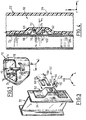
- la figure 1 est une vue en perspective éclatée qui représente schématiquement une portière de véhicule comportant une fenêtre et un support de rideau pare-soleil associé ,
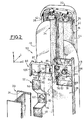
- la figure 2 est une vue en perspective éclatée avec arrachements qui représente schématiquement un agencement réalisé conformément aux enseignements de l'invention pour la fixation du support de rideau pare-soleil sur le montant de la fenêtre de la figure 1 ;
- la figure 3 est une vue en perspective qui représente partiellement l'agencement selon l'invention :
- la figure 4 est une vue en coupe axiale qui représente l'agencement selon l'invention lorsque le support de rideau occupe sa position montée sur le montant de la fenêtre.
- FIG. 1 is an exploded perspective view which schematically shows a vehicle door having a window and an associated sunshade curtain support,
- FIG. 2 is an exploded perspective view with cutouts which schematically represents an arrangement realized in accordance with the teachings of the invention for fixing the sun-curtain support on the amount of the window of FIG. 1;
- FIG. 3 is a perspective view which partly represents the arrangement according to the invention:
- Figure 4 is an axial sectional view which shows the arrangement according to the invention when the curtain support is in its position mounted on the amount of the window.
Pour la description de l'invention, on adoptera à titre non limitatif les orientations verticale, longitudinale et transversale selon le repère V, L, T indiqué aux figures.For the description of the invention, the vertical, longitudinal and transverse orientations according to the reference V, L, T indicated in the figures will be adopted without limitation.
Dans la description qui va suivre, des éléments identiques, similaires ou analogues seront désignés par les mêmes chiffres de référence.In the following description, identical, similar or similar elements will be designated by the same reference numerals.
Sur la figure 1, on a représenté une portière 10 de véhicule automobile vue de l'intérieur de l'habitacle.In Figure 1, there is shown a
La portière 10 comporte une fenêtre 12 délimitée par un encadrement 14The
Dans la suite de la description, on utilisera une orientation de l'extérieur vers l'intérieur de l'habitacle, suivant la direction longitudinale L, qui est ici sensiblement orthogonale au plan de la fenêtre 12. Des éléments seront donc qualifiés "d'internes" lorsqu'ils sont orientés vers l'intérieur de l'habitacle, et "d'externes" lorsqu'ils sont orientés vers l'extérieur de l'habitacle.In the remainder of the description, use will be made of an orientation of the outside towards the interior of the passenger compartment, along the longitudinal direction L, which is here substantially orthogonal to the plane of the
La fenêtre 12 comporte ici une vitre globalement triangulaire fixe 16 et une vitre globalement rectangulaire escamotable 18 qui sont séparées par un montant globalement vertical fixe 20.The
La portière 10 comporte par exemple un mécanisme (non représenté) permettant de faire descendre la vitre escamotable 18 à l'intérieur de la portière 10.The
Un support de rideau pare-soleil 22, ici en forme de boîtier globalement parallélépipédique, est prévu pour être fixé sur la paroi interne 24 du montant vertical 20.A sunshade curtain support 22, here in the form of a generally parallelepipedal housing, is provided to be fixed on the
Comme on peut le voir plus en détail sur la figure 2, le support 22 comporte deux parois verticales transversales respectivement interne 26 et externe 28, qui sont sensiblement parallèles à la paroi interne 24 du montant vertical 20.As can be seen in more detail in FIG. 2, the
Le support 22 contient deux rouleaux 30, 32 qui sont montés à rotation chacun autour d'un axe globalement vertical. Un rideau pare-soleil de vitre fixe 34 et un rideau pare-soleil de vitre escamotable 36 sont enroulés respectivement autour de chaque rouleau 30, 32.The
Le support 22 comporte deux parois verticales latérales 38, 40 sensiblement orthogonales au plan de la fenêtre 12. Chacune de ces parois latérales 38, 40 comporte une fente 42, 44 permettant de dérouler le rideau pare-soleil 34, 36 correspondant transversalement depuis l'intérieur du support 22 vers l'extrémité latérale en vis-à-vis de la fenêtre 12.The
Chaque rideau 34, 36 comporte, à son bord d'extrémité libre 46, 48, des moyens d'accrochage (non représentés) susceptibles de coopérer avec des moyens d'ancrage complémentaires (non représentés) portés par l'encadrement 14 de manière à permettre au rideau 34, 36 d'occuper une position d'occultation, totale ou partielle, de la fenêtre 12.Each
La fenêtre 12 comporte un agencement 50 pour la fixation du support 22 sur la paroi interne 24 du montant 20.The
Conformément aux enseignements de l'invention, l'agencement 50 comporte au moins une plaque de fixation 52, qui est portée par la paroi interne 24 du montant 20.According to the teachings of the invention, the
Selon le mode de réalisation représenté sur les figures 2 à 4. la plaque de fixation 52 est une plaque métallique rectangulaire qui est pliée de manière à former un bossage 54 s'étendant vers l'intérieur, à partir de la paroi interne 24 du montant vertical 20.According to the embodiment shown in FIGS. 2 to 4, the
La plaque de fixation 52 comporte, de part et d'autre du bossage 54, une portion d'extrémité supérieure 56 et une portion d'extrémité inférieure 58 planes, qui sont adjacentes à la paroi interne 24 du montant 20.The
Le sommet du bossage 54 est ici formé par une portion intermédiaire plane 60 de la plaque 52. qui est sensiblement parallèle à la paroi interne 24 du montant 20 et qui est décalée longitudinalement vers l'intérieur,The top of the boss 54 is here formed by a flat intermediate portion 60 of the
La portion intermédiaire 60 comporte un trou central 62 qui est prévu pour recevoir axialement un pion de fixation 64 porté par la paroi externe 28 du support 22.The intermediate portion 60 has a
Pour la suite de la description, on définit une direction axiale A1, correspondant à l'axe de montage du pion 64 dans le trou 62, cette direction étant sensiblement parallèle à la direction longitudinale L mentionnée précedemment.For the remainder of the description, an axial direction A1 is defined, corresponding to the mounting axis of the
Le pion de fixation 64 est agencé sur Ja paroi de fond 66 d'une cavité 68 révisée dans la paroi externe 28 du support 22.The
Comme on peut le voir plus particulièrement sur la figure 4, le pion de fixation 64 comporte ici un corps globalement cylindrique 70 muni d'une rainure transversale supérieure 72 et d'une rainure transversale inférieure 74.As can be seen more particularly in FIG. 4, the
Les deux rainures 72, 74 forment ici deux méplats dans le corps cylindrique 70 du pion de fixation 64.The two
Avantageusement, la paroi externe 28 du support 22 est réalisée par moulage, par exemple en matière plastique, et le pion 64 est réalisé venu de matière avec la paroi de fond 66 de la cavité 68.Advantageously, the
La cavité 68 a une forme sensiblement complémentaire de la plaque de fixation 52 et de son bossage 54.The cavity 68 has a shape substantially complementary to the
La cavité 68 comporte ici deux parois latérales 76, 78 sensiblement parallèles aux parois latérales 38, 40 du support 22, une paroi transversale supérieure 80 qui est globalement inclinée vers le haut et vers l'extérieur, et une paroi transversale inférieure 82 qui est globalement inclinée vers le bas et vers l'extérieur.The cavity 68 here comprises two
Selon le mode de réalisation représenté ici, la cavité 68 est décalée transversalement vers la paroi latérale 40 du support 22 située du côté de la vitre fixe 16, par rapport à un plan longitudinal vertical médian du support 22.According to the embodiment shown here, the cavity 68 is shifted transversely towards the
Avantageusement, la paroi latérale 76 de la cavité 68 qui est opposée à la vitre fixe 16 comporte une ouverture 84, ici de forme rectangulaire destinée à permettre l'insertion transversale d'une agrafe 86, en vue d'immobiliser le pion 64 dans le trou 62 de la plaque de fixation 52.Advantageously, the
L'agrafe 86 comporte ici un corps globalement parallélépipédique 87 qui est parallèle à la face externe 28 du support 22 et dont une extrémité transversale, du côté du pion de fixation 64, forme une fourche comportant deux bras transversaux parallèleres 88, 90.The staple 86 here comprises a generally
Chaque bras transversal 88, 90 comporte une surface radiale 92, 94, par rapport à l'axe de montage A1, orientée vers l'extérieur, qui est prévue pour venir partiellement en regard axialement d'une surface radiale de butée 96, 98 associée du pion 64, lorsque l'agrafe 86 occupe sa position montée qui est représentée en trait discontinu sur la figure 2 et en trait continu sur la figure 4.Each
Les surfaces radiales de butée 96, 98 du pion 64 sont ici formées par les surfaces radiales internes 100, 102, respectivement de la rainure supérieure 72 et de la rainure inférieure 74.The radial abutment surfaces 96, 98 of the
Avantageusement, le corps 87 de l'agrafe 86 comporte, dans sa surface transversale externe 104, une rainure transversale de guidage 106. La rainure 106 s'étend approximativement sur toute la longueur transversale de l'agrafe 86, jusqu'à l'extrémité libre du bras transversal inférieur 90,Advantageously, the
La rainure de guidage 106 est prévue pour coopérer, par exemple, avec des ergots ou une nervure complémentaire (non représentés) réalisés sur la face interne de la paroi externe 28 du support 22, de manière à guider transversalement l'agrafe 86 dans le support 22.The
Le support 22 comporte un logement 108 qui est formé sur la face interne 29 de la paroi externe 28 du support 22, et qui est agencé transversalement entre l'ouverture 84 de la cavité 68 et la paroi latérale opposée 38 du support 22.The
Le logement 108 est prévu pour recevoir le corps 87 de l'agrafe 86 de manière complémentaire. Il comporte une découpe 110 qui est réalisée dans la paroi latérale 38 du support 22, transversalement en vis-à-vis de l'ouverture 84, et qui permet l'insertion transversale de l'agrafe 86 dans le support 22.The
Avantageusement, l'agrafe 86 comporte une plaque axiale verticale, ou plaque d'extrémité 112, qui est agencée à son extrémité transversale opposée au pion de fixation 64, de manière à fermer la découpe 110 du logement 108 et à former une butée transversale pour l'agrafe 86, lorsque l'agrafe 86 occupe sa position montée.Advantageously, the
On décrira maintenant l'opération de montage du support 22 sur le montant vertical 20 de la fenêtre 12,We will now describe the mounting operation of the
Le montant vertical 20 étant préalablement équipé de sa plaque de fixation 52, qui est par exemple rapportée sur la paroi interne 24 du montant 20 par soudage, on amène axialement le pion de fixation 64 dans le trou 62 de la plaque de fixation 52.The
Lorsque le pion de fixation 64 est reçu entièrement dans le trou 62, il s'étend axialement du côté de la face externe de la portion centrale 60 de la plaque de fixation 52.When the securing
On vient alors insérer l'agrafe 86 transversalement dans son logement 108, à travers la découpe 110, jusqu'à ce que les bras transversaux 88, 90 de l'agrafe 86 traversent l'ouverture 84 et qu'ils soient reçus dans les rainures correspondantes 72, 74 du pion de fixation 64.The staple 86 is then inserted transversely into its
La plaque d'extrémité 112 de l'agrafe 86 vient alors en butée transversale contre le bord de la découpe 110, et l'agrafe 86 occupe sa position montée, comme on l'a représenté en trait discontinu sur la figure 2 et en trait continu sur la figure 4.The end plate 112 of the staple 86 then comes into transverse abutment against the edge of the blank 110, and the staple 86 occupies its mounted position, as shown in dashed lines in FIG. continuous in Figure 4.
Avantageusement, dans la position montée de l'agrafe 86, la plaque d'extrémité 112 est affleurante avec la paroi latérale associée 38 du support 22.Advantageously, in the mounted position of the staple 86, the end plate 112 is flush with the associated
On note que les bras 88, 90 de l'agrafe 86 peuvent comporter des moyens d'emboîtement (non représentés), susceptibles de coopérer avec le pion de fixation 64, par exemple par déformation élastique, de manière à retenir transversalement l'agrafe 86 en position montée.It is noted that the
Dans la position montée de l'agrafe 86, le support 22 occupe sa position montée sur la paroi interne 24 du montant vertical 20. telle qu'on l'a représentée sur la figure 4.In the mounted position of the staple 86, the
Le support 22 est alors retenu sur le montant 20, axialement par l'agrafe 86 dont les surfaces radiales 92, 94 sont en appui axial contre les surfaces de butée associées 100, 102 du pion 64, et verticalement par le pion 64 dont le corps cylindrique 70 est en appui radialement contre les bords du trou 62 de la plaque de fixation 52.The
On note que la plaque de fixation 52 forme, entre la portion intermédiaire 60 et la paroi interne 24 du montant 20, et entre les deux portions d'extrémité 56, 58, un espace qui permet le passage de l'agrafe 86 entre la portion intermédiaire 60 et la paroi interne 24 du montant 20.It is noted that the fixing
Un avantage de l'agencement selon l'invention est que l'insertion de l'agrafe 86 peut être réalisée "en aveugle", notamment grâce au guidage transversal de l'agrafe 86 dans le support 22.An advantage of the arrangement according to the invention is that the insertion of the staple 86 can be performed "blindly", in particular by means of the transverse guidance of the staple 86 in the
De plus, l'agrafe 86 peut être préalablement insérée partiellement dans son logement 108, comme on l'a représenté sur la figure 2, avant le montage du support 22 sur le montant 20.In addition, the staple 86 may be inserted partially into its
Selon cette variante de montage, on amène axialement le support 22, déjà équipé de l'agrafe 86, sur le montant 20, en engageant le pion 64 dans le trou 62. Il suffit alors de pousser transversalement l'agrafe 86 jusqu'à sa position de butée transversale, de sorte que le support 22 soit retenu dans sa position montée.According to this mounting variant, the
On note que l'agencement du pion de fixation 64 dans une cavité 68 permet de minimiser l'espace axial entre la paroi externe 28 du support 22 et la paroi interne 24 du montant 20, comme cela apparaît notamment sur la figure 4. L'agencement 50 est alors "camouflé" et logé dans l'épaisseur axiale du support 22.Note that the arrangement of the fixing
Bien entendu, on comprendra que le support 22 et le montant 20 peuvent comporter plusieurs agencements 50 tels que celui qui a été décrit précédemment. En particulier, le montant 20 peut comporter deux plaques de fixation 52, agencées respectivement au voisinage des extrémités supérieure et inférieure du montant 20. et le support 22 peut comporter deux pions de fixation 64 associés, ainsi que deux agrafes 86 associées.Of course, it will be understood that the
Claims (10)
- An arrangement (50) for fastening a sunscreen support (22) to the inner wall (24) of a substantially vertical upright (20) of a side window (12) of an automobile vehicle, of the type in which the support (22) is fastened on the upright (20) so that the screen (34, 36) may occupy at least a screening position, in which the screen (34, 36) covers at least part of the window (12), and a retracted position, characterised in that:- the inner wall (24) of the upright (20) comprises at least one fastening plate (52) which is provided with an axial hole,- the outer wall (28) of the support (22) comprises at least one fastening pin (64) which extends axially outwards in order to be received in the hole (62) of the plate (52) and which comprises at least one substantially radial, inwardly oriented abutment surface (100,102),and in that in the position in which the support (22) is mounted on the upright (20), a clip (86) is inserted transversely from the side of the outer surface of the fastening plate (52) so that a substantially radial, outwardly oriented bearing surface (92, 94) of the clip (86) is positioned axially opposite the abutment surface (100, 102) of the pin (64) and axially retains the pin (64) in the hole (62).
- An arrangement (50) as claimed in the preceding claim, characterised in that the clip (86) comprises two bearing surfaces (92, 94) belonging respectively to two arms (88,90) of the clip (86) which are parallel to the transverse direction of insertion, and in that the pin (64) comprises two substantially diametrically opposed abutment surfaces (100, 102) which are respectively associated with each bearing surface (92; 94) of me clip (86).
- An arrangement (50) as claimed in any one of the preceding claims, characterised in that the body (70) of the pin (64) is provided with at least one transverse groove (72, 74) and in that a substantially radial surface (100, 102) of the groove (72, 74) forms the abutment surface of the pin (64).
- An arrangement (50) as claimed in any one of the preceding claims, characterised in that the pin (64) extends axially from the base of a cavity (68) provided in the outer wall (26) of the support (22) and in that the fastening plate (52) forms a boss (54) which is substantially complementary with the cavity (68), the hole (62) being arranged substantially at the top of the boss (54) so as to minimise the axial space between the outer wall (28) of the support (22) and the inner wall (24) of the uptight (20).
- An arrangement (50) as claimed in the preceding claim, characterised in that the cavity (68) comprises a substantially vertical axial wall (76) which is provided with a transverse opening (84) to enable the passage of the clip (86).
- An arrangement (50) as claimed in the preceding claim, characterised in that the support (22) comprises a housing (108) adapted to receive the clip (86) in a complementary manner.
- An arrangement (50) as claimed in the preceding claim, characterised in that the housing (108) comprises means for the transverse guiding of the clip (86).
- An arrangement (50) as;claimed in any one of the preceding claims, characterised in that the body (70) of the pin (64) is substantially cylindrical.
- An arrangement (50) as claimed in any one of the preceding claims, characterised in that the fastening plate (52) is mounted on the upright (20) of the window (12).
- An arrangement (50) as claimed in the preceding claim, characterised in that the fastening plate (52) is made from sheet metal and in that it is welded to the upright (20) of the window (12).
Applications Claiming Priority (2)
| Application Number | Priority Date | Filing Date | Title |
|---|---|---|---|
| FR0304969 | 2003-04-23 | ||
| FR0304969A FR2854105B1 (en) | 2003-04-23 | 2003-04-23 | ARRANGEMENT FOR FASTENING A SUNSCREEN RIDER SUPPORT |
Publications (2)
| Publication Number | Publication Date |
|---|---|
| EP1470942A1 EP1470942A1 (en) | 2004-10-27 |
| EP1470942B1 true EP1470942B1 (en) | 2007-03-21 |
Family
ID=32947363
Family Applications (1)
| Application Number | Title | Priority Date | Filing Date |
|---|---|---|---|
| EP20040300214 Expired - Fee Related EP1470942B1 (en) | 2003-04-23 | 2004-04-21 | Arrangement to fasten a support of a sun curtain |
Country Status (4)
| Country | Link |
|---|---|
| EP (1) | EP1470942B1 (en) |
| DE (1) | DE602004005372T2 (en) |
| ES (1) | ES2280020T3 (en) |
| FR (1) | FR2854105B1 (en) |
Cited By (1)
| Publication number | Priority date | Publication date | Assignee | Title |
|---|---|---|---|---|
| US11670788B2 (en) | 2008-12-02 | 2023-06-06 | General Electric Company | Apparatus and method for high efficiency operation of fuel cell systems |
Families Citing this family (1)
| Publication number | Priority date | Publication date | Assignee | Title |
|---|---|---|---|---|
| FR2904265B1 (en) * | 2006-07-28 | 2008-11-21 | Wagon Sas | MAITIEN ELEMENT OCCULTATION DEVICE AND CORRESPONDING VEHICLE |
Family Cites Families (3)
| Publication number | Priority date | Publication date | Assignee | Title |
|---|---|---|---|---|
| DE3822378C2 (en) * | 1988-07-01 | 1994-10-27 | Bayerische Motoren Werke Ag | Window roller blind for a motor vehicle |
| DE50000785D1 (en) * | 2000-03-03 | 2003-01-02 | Schwab Technik Gmbh | Window roller blind device for vehicle windows |
| US6477485B1 (en) | 2000-10-27 | 2002-11-05 | Otis Elevator Company | Monitoring system behavior using empirical distributions and cumulative distribution norms |
-
2003
- 2003-04-23 FR FR0304969A patent/FR2854105B1/en not_active Expired - Fee Related
-
2004
- 2004-04-21 DE DE602004005372T patent/DE602004005372T2/en not_active Expired - Lifetime
- 2004-04-21 EP EP20040300214 patent/EP1470942B1/en not_active Expired - Fee Related
- 2004-04-21 ES ES04300214T patent/ES2280020T3/en not_active Expired - Lifetime
Cited By (1)
| Publication number | Priority date | Publication date | Assignee | Title |
|---|---|---|---|---|
| US11670788B2 (en) | 2008-12-02 | 2023-06-06 | General Electric Company | Apparatus and method for high efficiency operation of fuel cell systems |
Also Published As
| Publication number | Publication date |
|---|---|
| FR2854105A1 (en) | 2004-10-29 |
| DE602004005372D1 (en) | 2007-05-03 |
| DE602004005372T2 (en) | 2007-11-29 |
| FR2854105B1 (en) | 2005-07-01 |
| EP1470942A1 (en) | 2004-10-27 |
| ES2280020T3 (en) | 2007-09-01 |
Similar Documents
| Publication | Publication Date | Title |
|---|---|---|
| EP2621745B1 (en) | Glass panel having an encapsulated profiled joint and insert attached to the joint, element for attaching the insert for the glass panel, and method for manufacturing the glass panel | |
| FR2736025A1 (en) | Motor vehicle windscreen wiper connector with cover cap, | |
| WO2011064484A1 (en) | Extractable key for a glass panel joint and related extraction method | |
| EP3681746B1 (en) | Windows sealing strip with ease of mounting | |
| EP2648996A1 (en) | Device and assembly for supporting a pair of windshield wipers, and corresponding packaging and assembly method | |
| EP3045357B1 (en) | Cap for a windscreen wiper for covering an end portion of a wiper arm | |
| EP0538093A1 (en) | Streamlined windscreen wiper, in particular for motor vehicle | |
| EP1470942B1 (en) | Arrangement to fasten a support of a sun curtain | |
| EP3375675B1 (en) | Cap, connecting device for mounting a windscreen wiper on a corresponding windscreen wiper arm and windscreen wiping system | |
| EP0667261B1 (en) | Luggage carrier for vehicles | |
| FR2696393A1 (en) | Vehicle windscreen wiper - has protective cover with internal rails sliding into grooves in drive head | |
| EP0985567B1 (en) | Roller blind with enclosure forming the upper part of a door; corresponding door and method to install | |
| EP0724052B1 (en) | Vehicle door handle with quick wedge-cam assembly | |
| FR2878587A1 (en) | Roof cover fastening clip for motor vehicle, has attachments with terminals turned towards direction opposite to another direction along which lugs are directed inside clip, and other lugs extending, towards outside clip, from attachments | |
| EP0169499B1 (en) | Carton and device for closing it | |
| EP0567389B1 (en) | Wiperarm incorporating at least one contact pressure spring | |
| EP3983244B1 (en) | Mounting guide for a motor vehicle panhard bar | |
| EP2089245B1 (en) | Tailgate structure for an automotive vehicle and automotive vehicle with such structure | |
| FR3075303B1 (en) | SEAL FOR MOTOR VEHICLE COMPRISING AN ADHESIVE MEANS AND AT LEAST ONE FASTENING CLIP | |
| EP2050603B1 (en) | Roller blind for an automobile, with hooking element clipped and maintained on its support, corresponding support and vehicle. | |
| FR2713170A1 (en) | Carrier for mineral number plate for vehicle | |
| EP0566487B1 (en) | Device for attaching a seat cover for a padded seat; method for making it and mounting it | |
| FR2751272A1 (en) | Screening shade for window openings in vehicles | |
| EP0589798A1 (en) | Windscreen wiper arm with moulded link piece, especially for motor vehicles | |
| FR3103455A1 (en) | Vehicle fitted with an optimized instrument panel mounting device |
Legal Events
| Date | Code | Title | Description |
|---|---|---|---|
| PUAI | Public reference made under article 153(3) epc to a published international application that has entered the european phase |
Free format text: ORIGINAL CODE: 0009012 |
|
| AK | Designated contracting states |
Kind code of ref document: A1 Designated state(s): AT BE BG CH CY CZ DE DK EE ES FI FR GB GR HU IE IT LI LU MC NL PL PT RO SE SI SK TR |
|
| AX | Request for extension of the european patent |
Extension state: AL HR LT LV MK |
|
| 17P | Request for examination filed |
Effective date: 20050331 |
|
| AKX | Designation fees paid |
Designated state(s): AT BE BG CH CY CZ DE DK EE ES FI FR GB GR HU IE IT LI LU MC NL PL PT RO SE SI SK TR |
|
| RBV | Designated contracting states (corrected) |
Designated state(s): AT BE BG CH CY CZ DE DK EE ES FI FR GB GR HU IE IT LI LU MC NL PL PT RO SE SI SK TR |
|
| GRAP | Despatch of communication of intention to grant a patent |
Free format text: ORIGINAL CODE: EPIDOSNIGR1 |
|
| GRAS | Grant fee paid |
Free format text: ORIGINAL CODE: EPIDOSNIGR3 |
|
| GRAA | (expected) grant |
Free format text: ORIGINAL CODE: 0009210 |
|
| AK | Designated contracting states |
Kind code of ref document: B1 Designated state(s): BE DE ES GB |
|
| REG | Reference to a national code |
Ref country code: GB Ref legal event code: FG4D Free format text: NOT ENGLISH |
|
| GBT | Gb: translation of ep patent filed (gb section 77(6)(a)/1977) |
Effective date: 20070404 |
|
| REF | Corresponds to: |
Ref document number: 602004005372 Country of ref document: DE Date of ref document: 20070503 Kind code of ref document: P |
|
| REG | Reference to a national code |
Ref country code: ES Ref legal event code: FG2A Ref document number: 2280020 Country of ref document: ES Kind code of ref document: T3 |
|
| PLBE | No opposition filed within time limit |
Free format text: ORIGINAL CODE: 0009261 |
|
| STAA | Information on the status of an ep patent application or granted ep patent |
Free format text: STATUS: NO OPPOSITION FILED WITHIN TIME LIMIT |
|
| 26N | No opposition filed |
Effective date: 20071227 |
|
| PGFP | Annual fee paid to national office [announced via postgrant information from national office to epo] |
Ref country code: DE Payment date: 20160421 Year of fee payment: 13 Ref country code: GB Payment date: 20160421 Year of fee payment: 13 Ref country code: ES Payment date: 20160413 Year of fee payment: 13 |
|
| PGFP | Annual fee paid to national office [announced via postgrant information from national office to epo] |
Ref country code: BE Payment date: 20160420 Year of fee payment: 13 |
|
| REG | Reference to a national code |
Ref country code: DE Ref legal event code: R119 Ref document number: 602004005372 Country of ref document: DE |
|
| GBPC | Gb: european patent ceased through non-payment of renewal fee |
Effective date: 20170421 |
|
| PG25 | Lapsed in a contracting state [announced via postgrant information from national office to epo] |
Ref country code: DE Free format text: LAPSE BECAUSE OF NON-PAYMENT OF DUE FEES Effective date: 20171103 |
|
| PG25 | Lapsed in a contracting state [announced via postgrant information from national office to epo] |
Ref country code: GB Free format text: LAPSE BECAUSE OF NON-PAYMENT OF DUE FEES Effective date: 20170421 |
|
| REG | Reference to a national code |
Ref country code: BE Ref legal event code: MM Effective date: 20170430 |
|
| PG25 | Lapsed in a contracting state [announced via postgrant information from national office to epo] |
Ref country code: BE Free format text: LAPSE BECAUSE OF NON-PAYMENT OF DUE FEES Effective date: 20170430 |
|
| REG | Reference to a national code |
Ref country code: ES Ref legal event code: FD2A Effective date: 20180629 |
|
| PG25 | Lapsed in a contracting state [announced via postgrant information from national office to epo] |
Ref country code: ES Free format text: LAPSE BECAUSE OF NON-PAYMENT OF DUE FEES Effective date: 20170422 |