EP3402703B1 - Adapter for connecting a wiper blade to a drive arm - Google Patents
Adapter for connecting a wiper blade to a drive arm Download PDFInfo
- Publication number
- EP3402703B1 EP3402703B1 EP17700134.4A EP17700134A EP3402703B1 EP 3402703 B1 EP3402703 B1 EP 3402703B1 EP 17700134 A EP17700134 A EP 17700134A EP 3402703 B1 EP3402703 B1 EP 3402703B1
- Authority
- EP
- European Patent Office
- Prior art keywords
- adapter
- patterns
- walls
- lateral faces
- brush
- Prior art date
- Legal status (The legal status is an assumption and is not a legal conclusion. Google has not performed a legal analysis and makes no representation as to the accuracy of the status listed.)
- Active
Links
- 239000010432 diamond Substances 0.000 claims description 4
- XLYOFNOQVPJJNP-UHFFFAOYSA-N water Substances O XLYOFNOQVPJJNP-UHFFFAOYSA-N 0.000 description 9
- 244000007853 Sarothamnus scoparius Species 0.000 description 3
- 238000000034 method Methods 0.000 description 3
- 238000005452 bending Methods 0.000 description 2
- 230000000295 complement effect Effects 0.000 description 2
- 238000005516 engineering process Methods 0.000 description 2
- 241000256815 Apocrita Species 0.000 description 1
- 230000004888 barrier function Effects 0.000 description 1
- 230000005540 biological transmission Effects 0.000 description 1
- 239000000428 dust Substances 0.000 description 1
- 230000000694 effects Effects 0.000 description 1
- 239000013013 elastic material Substances 0.000 description 1
- 238000002955 isolation Methods 0.000 description 1
- 238000007747 plating Methods 0.000 description 1
- 150000003839 salts Chemical class 0.000 description 1
- 238000000926 separation method Methods 0.000 description 1
- 235000019832 sodium triphosphate Nutrition 0.000 description 1
Images
Classifications
-
- B—PERFORMING OPERATIONS; TRANSPORTING
- B60—VEHICLES IN GENERAL
- B60S—SERVICING, CLEANING, REPAIRING, SUPPORTING, LIFTING, OR MANOEUVRING OF VEHICLES, NOT OTHERWISE PROVIDED FOR
- B60S1/00—Cleaning of vehicles
- B60S1/02—Cleaning windscreens, windows or optical devices
- B60S1/04—Wipers or the like, e.g. scrapers
- B60S1/32—Wipers or the like, e.g. scrapers characterised by constructional features of wiper blade arms or blades
- B60S1/40—Connections between blades and arms
- B60S1/4006—Connections between blades and arms for arms provided with a hook-shaped end
- B60S1/4009—Connections between blades and arms for arms provided with a hook-shaped end comprising a detachable intermediate element mounted on the hook-shaped end
- B60S1/4016—Connections between blades and arms for arms provided with a hook-shaped end comprising a detachable intermediate element mounted on the hook-shaped end the element being provided with retention means co-operating with the hook-shaped end of the arm
- B60S1/4019—Connections between blades and arms for arms provided with a hook-shaped end comprising a detachable intermediate element mounted on the hook-shaped end the element being provided with retention means co-operating with the hook-shaped end of the arm the retention means being protrusions or holes
-
- B—PERFORMING OPERATIONS; TRANSPORTING
- B60—VEHICLES IN GENERAL
- B60S—SERVICING, CLEANING, REPAIRING, SUPPORTING, LIFTING, OR MANOEUVRING OF VEHICLES, NOT OTHERWISE PROVIDED FOR
- B60S1/00—Cleaning of vehicles
- B60S1/02—Cleaning windscreens, windows or optical devices
- B60S1/04—Wipers or the like, e.g. scrapers
- B60S1/32—Wipers or the like, e.g. scrapers characterised by constructional features of wiper blade arms or blades
- B60S1/38—Wiper blades
- B60S1/3848—Flat-type wiper blade, i.e. without harness
- B60S1/3849—Connectors therefor; Connection to wiper arm; Attached to blade
- B60S1/3851—Mounting of connector to blade assembly
- B60S1/3858—Mounting of connector to blade assembly with protrusions cooperating with holes
-
- B—PERFORMING OPERATIONS; TRANSPORTING
- B60—VEHICLES IN GENERAL
- B60S—SERVICING, CLEANING, REPAIRING, SUPPORTING, LIFTING, OR MANOEUVRING OF VEHICLES, NOT OTHERWISE PROVIDED FOR
- B60S1/00—Cleaning of vehicles
- B60S1/02—Cleaning windscreens, windows or optical devices
- B60S1/04—Wipers or the like, e.g. scrapers
- B60S1/32—Wipers or the like, e.g. scrapers characterised by constructional features of wiper blade arms or blades
- B60S1/40—Connections between blades and arms
- B60S1/4006—Connections between blades and arms for arms provided with a hook-shaped end
- B60S1/4009—Connections between blades and arms for arms provided with a hook-shaped end comprising a detachable intermediate element mounted on the hook-shaped end
- B60S2001/4012—Connections between blades and arms for arms provided with a hook-shaped end comprising a detachable intermediate element mounted on the hook-shaped end the element being provided with bearing surfaces on its side walls
Definitions
- the brush is attached to the drive arm by a connection system comprising an adapter and a connector.
- the connector is a part which is secured to the brush and which can be integrated into the brush.
- the connector is fixed directly to the scraper blade or the flat blade, while the adapter is secured to the arm.
- the adapter is an intermediate piece which allows the connection and fixing of the connector on the drive arm. It is configured to cooperate with a head or end piece of the drive arm.
- the connector and the adapter each comprise articulation means configured to cooperate with means complementary to the other member, to define at least one transverse axis of pivoting of the connector with respect to the adapter, which is a pivot axis of the brush with respect to the arm.
- one of the members, such as the connector generally comprises a substantially cylindrical physical axis which defines the axis of articulation and which is received in a housing of complementary shape to the other member.
- the adapter is mounted in a housing of the connector or of the brush and comprises two substantially parallel walls and at a distance from each other, connected together by at least one connecting element.
- the walls of the adapter have internal lateral faces between which this connecting element extends, and external lateral faces which are intended to be located opposite internal lateral faces of the housing of the connector or of the arm, and to cooperate by sliding with these faces when the adapter swivels with respect to the connector or the brush.
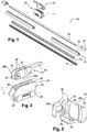
- the brush 10 comprises substantially in its middle a connector 24 which is intended to receive the adapter 12, the connector-adapter assembly forming a system for connecting the brush 10 to a drive arm (not shown in figure 1 ).
- the adapter 12 comprises two parallel side walls 28 which are at a distance from each other and connected together by at least one transverse wall 30 ( figure 3 ).
- the walls 28 have internal lateral faces 28a between which the transverse wall 30 extends, and external lateral faces 28b comprising protruding patterns 32.
- lug 44 positioned on the transverse wall 30, which allows, in cooperation with an orifice (not shown) made in the U-shaped end portion of the arm 26, to secure the latter with the adapter 12.
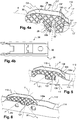
- the patterns 132 are distributed in rows and columns.
- the patterns 132 here have identical geometric shapes and are here squares or diamonds.
- the pattern lines are straight and parallel and the pattern columns are also straight and parallel.
- the patterns 132 are diamonds, the lines L1 ′, L2 ′, etc., of patterns are parallel to the elongation axis X of the adapter, and the columns of patterns C1, C2, etc., are perpendicular to this X axis.
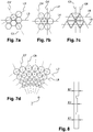
- the channels 150 form a grid or a grid.
- the channels 150 have in section a shape substantially in V. Alternatively, they could have another shape in section, such as in U.
- the patterns are polygons and more exactly hexagons. They are divided into rows and columns.
Description
La présente invention concerne notamment un adaptateur pour relier un balai d'essuie-glace à un bras d'entraînement, en particulier de véhicule automobile.The present invention relates in particular to an adapter for connecting a wiper blade to a drive arm, in particular of a motor vehicle.
Une automobile est classiquement équipée d'essuie-glaces pour assurer un lavage du pare-brise et éviter que la vision qu'a le conducteur de son environnement ne soit perturbée. Ces essuie-glaces comprennent en général un bras d'entrainement, effectuant un mouvement de va-et-vient angulaire, et des balais allongés, porteurs eux-mêmes de lames racleuses réalisées en une matière élastique. Ces lames frottent contre le pare-brise et évacuent l'eau en l'amenant en dehors du champ de vision du conducteur. Les balais sont réalisés sous la forme, soit, dans une version classique, d'étriers articulés qui tiennent la lame racleuse en plusieurs endroits discrets en lui conférant un cintrage lui permettant d'épouser l'éventuelle courbure du pare-brise, soit, dans une version plus récente dénommée "flat blade" (pour "lame plate"), d'un ensemble semi-rigide qui maintient la lame racleuse sur toute sa longueur grâce à une ou des vertèbres de cintrage permettant d'appliquer le balai sur le pare-brise sans avoir à utiliser d'étriers.An automobile is conventionally equipped with wipers to wash the windshield and prevent the driver's vision of his environment from being disturbed. These wipers generally comprise a drive arm, performing an angular reciprocating movement, and elongated blades, themselves carrying scraper blades made of an elastic material. These blades rub against the windshield and evacuate the water by bringing it out of the driver's field of vision. The brushes are made in the form, either, in a classic version, of articulated stirrups which hold the scraper blade in several discreet places by giving it a bending allowing it to marry the possible curvature of the windshield, or, in a more recent version called "flat blade" (for a "flat blade"), of a semi-rigid assembly which holds the scraper blade over its entire length thanks to one or more bending vertebrae making it possible to apply the broom to the barrier -brise without having to use stirrups.
Dans les deux solutions, le balai est rattaché au bras d'entraînement par un système de connexion comportant un adaptateur et un connecteur. Le connecteur est une pièce qui est solidarisée au balai et qui peut être intégré au balai. Le connecteur est fixé directement sur la lame racleuse ou sur le flat blade, alors que l'adaptateur est solidaire du bras. L'adaptateur est une pièce intermédiaire qui permet la liaison et la fixation du connecteur sur le bras d'entraînement. Il est configuré pour coopérer avec une tête ou pièce terminale du bras d'entraînement.In both solutions, the brush is attached to the drive arm by a connection system comprising an adapter and a connector. The connector is a part which is secured to the brush and which can be integrated into the brush. The connector is fixed directly to the scraper blade or the flat blade, while the adapter is secured to the arm. The adapter is an intermediate piece which allows the connection and fixing of the connector on the drive arm. It is configured to cooperate with a head or end piece of the drive arm.
Le connecteur et l'adaptateur comprennent chacun des moyens d'articulation configurés pour coopérer avec des moyens complémentaires de l'autre organe, pour définir au moins un axe transversal de pivotement du connecteur vis-à-vis de l'adaptateur, qui est un axe de pivotement du balai vis-à-vis du bras. Dans la technique actuelle, l'un des organes, tel que le connecteur, comprend en général un axe physique sensiblement cylindrique qui définit l'axe d'articulation et qui est reçu dans un logement de forme complémentaire de l'autre organe.The connector and the adapter each comprise articulation means configured to cooperate with means complementary to the other member, to define at least one transverse axis of pivoting of the connector with respect to the adapter, which is a pivot axis of the brush with respect to the arm. In the current technique, one of the members, such as the connector, generally comprises a substantially cylindrical physical axis which defines the axis of articulation and which is received in a housing of complementary shape to the other member.
Dans certains cas, l'adaptateur est monté dans un logement du connecteur ou du balai et comprend deux parois sensiblement parallèles et à distance l'une de l'autre, reliées ensemble par au moins un élément de liaison. Les parois de l'adaptateur comportent des faces latérales internes entre lesquelles s'étend cet élément de liaison, et des faces latérales externes qui sont destinées à être situées en regard de faces latérales internes du logement du connecteur ou du bras, et à coopérer par glissement avec ces faces lors du pivotement de l'adaptateur vis-à-vis du connecteur ou du balai.In some cases, the adapter is mounted in a housing of the connector or of the brush and comprises two substantially parallel walls and at a distance from each other, connected together by at least one connecting element. The walls of the adapter have internal lateral faces between which this connecting element extends, and external lateral faces which are intended to be located opposite internal lateral faces of the housing of the connector or of the arm, and to cooperate by sliding with these faces when the adapter swivels with respect to the connector or the brush.
Pour cela, les faces latérales externes des parois de l'adaptateur comprennent des motifs en saillie qui définissent à leurs sommets des surfaces d'appui et de guidage. Dans la technique actuelle telle qu'illustrée par le document
L'invention propose un perfectionnement à cette technologie.The invention proposes an improvement to this technology.
L'invention propose à cet effet un adaptateur pour relier un balai d'essuie-glace à un bras d'entraînement, l'adaptateur comprenant deux parois sensiblement parallèles reliées ensemble par au moins un élément de liaison, lesdites parois comportant des premières faces latérales internes entre lesquelles s'étend ledit au moins un élément de liaison, et des faces latérales externes comportant des motifs en saillie de guidage par glissement, lesdits motifs étant répartis en lignes et colonnes.To this end, the invention provides an adapter for connecting a wiper blade to a drive arm, the adapter comprising two substantially parallel walls connected together by at least one connecting element, said walls comprising first lateral faces. internal between which extends said at least one connecting element, and external lateral faces comprising protruding guide patterns by sliding, said patterns being distributed in rows and columns.
L'invention présente de nombreux avantages. Elle est applicable à un adaptateur de petites dimensions et les motifs, qui peuvent être plus nombreux du fait de leur disposition en lignes et colonnes, peuvent avoir une ou des épaisseurs relativement faibles par rapport à la technique antérieure. Pour des parois d'épaisseur donnée, elle permet de rigidifier les parois ainsi que l'adaptateur dans son ensemble. Ceci est particulièrement avantageux car la rigidité de l'adaptateur peut avoir une influence sur la précision de contrôle du balai en fonctionnement. La distribution des motifs permet également d'améliorer le guidage de l'adaptateur en limitant les portions de parois non guidées. L'invention permet par ailleurs de conserver un bon drainage de l'eau entre les parois de l'adaptateur et du connecteur ou du balai, les motifs en saillie délimitant entre eux des canaux de drainage. Ceci permet d'éviter des phénomènes d'adhésion des parois en particulier lorsque leurs surfaces en contact sont lisses et séparées par un film d'eau. L'invention permet de mieux maîtriser l'épaisseur de l'adaptateur. Enfin, elle permet un guidage latéral optimal et une force de transmission optimale entre l'adaptateur et le connecteur ou le balai.The invention has many advantages. It is applicable to an adapter of small dimensions and the patterns, which may be more numerous due to their arrangement in rows and columns, may have one or more thicknesses relatively small compared to the prior art. For walls of given thickness, it makes it possible to stiffen the walls as well as the adapter as a whole. This is particularly advantageous since the rigidity of the adapter can have an influence on the precision of control of the brush in operation. The distribution of the patterns also makes it possible to improve the guidance of the adapter by limiting the portions of unguided walls. The invention also makes it possible to maintain good drainage of water between the walls of the adapter and of the connector or of the brush, the protruding patterns delimiting between them drainage channels. This makes it possible to avoid adhesion phenomena of the walls in particular when their surfaces in contact are smooth and separated by a film of water. The invention makes it possible to better control the thickness of the adapter. Finally, it allows optimal lateral guidance and an optimal transmission force between the adapter and the connector or the brush.
Selon l'invention, lesdits motifs sont séparés les uns des autres par des rainures formant des canaux de drainage. De plus, les canaux de drainage sont, sur au moins une partie de leur longueur, inclinés par rapport à l'axe longitudinal de l'adaptateur.According to the invention, said patterns are separated from each other by grooves forming drainage channels. In addition, the drainage channels are, over at least part of their length, inclined relative to the longitudinal axis of the adapter.
Dans le cadre de l'invention, l'expression « être incliné par rapport à l'axe longitudinal de l'adaptateur signifie ne pas être parallèle ni perpendiculaire au dit axe. Autrement dit, l'angle formé par l'inclinaison avec l'axe longitudinal est compris strictement entre 0° et 90°.In the context of the invention, the expression “being inclined relative to the longitudinal axis of the adapter means not being parallel or perpendicular to said axis. In other words, the angle formed by the inclination with the longitudinal axis is strictly between 0 ° and 90 °.
L'adaptateur selon l'invention peut comprendre une ou plusieurs des caractéristiques suivantes, prises isolément les unes des autres ou en combinaison les unes avec les autres :
- lesdits motifs recouvrent plus de 50%, et de préférence plus de 80%, desdites faces latérales externes,
- lesdits motifs ont des formes géométriques identiques,
- au moins une partie desdits motifs forme des carrés, des ronds, des losanges, des triangles, et/ou des polygones (par exemple du type nid d'abeilles),
- les motifs ont tous la même épaisseur,
- l'adaptateur comprend, sur chacune desdites faces latérales externes, des premiers motifs d'épaisseur E1 et des seconds motifs d'épaisseur E2 différente de E1,
- chacune desdites faces latérales externes comprend plus de dix motifs,
- ledit au moins élément de liaison définit une goulotte qui est sensiblement perpendiculaire auxdites parois et qui est configuré pour recevoir et guider un axe de rotation dudit adaptateur,
- au moins certaines des lignes et/ou des colonnes sont rectilignes,
- au moins certaines des lignes et/ou des colonnes sont parallèles,
- au moins certaines des lignes et/ou des colonnes sont incurvées,
- au moins certaines des lignes sont perpendiculaires à au moins certaines des colonnes,
- lesdits canaux de drainage forment un quadrillage,
- chacune desdites rainures a une largeur comprise entre 0,1 et 1 mm et par exemple de l'ordre de 0,5mm, et
- chacune desdites rainures a en section une forme en U ou V.
- said patterns cover more than 50%, and preferably more than 80%, of said external lateral faces,
- said patterns have identical geometric shapes,
- at least part of said patterns form squares, circles, diamonds, triangles, and / or polygons (for example of the honeycomb type),
- the patterns are all the same thickness,
- the adapter comprises, on each of said external lateral faces, first patterns of thickness E1 and second patterns of thickness E2 different from E1,
- each of said external lateral faces comprises more than ten patterns,
- said at least one connecting element defines a chute which is substantially perpendicular to said walls and which is configured to receive and guide an axis of rotation of said adapter,
- at least some of the rows and / or columns are straight,
- at least some of the rows and / or columns are parallel,
- at least some of the rows and / or columns are curved,
- at least some of the rows are perpendicular to at least some of the columns,
- said drainage channels form a grid,
- each of said grooves has a width of between 0.1 and 1 mm and for example of the order of 0.5 mm, and
- each of said grooves has a U or V shape in section.
La présente invention concerne également un balai ou un bras d'essuie-glace, caractérisé en ce qu'il comprend ou porte un adaptateur tel que décrit ci-dessus.The present invention also relates to a wiper blade or arm, characterized in that it comprises or carries an adapter as described above.
L'invention sera mieux comprise et d'autres détails, caractéristiques et avantages de l'invention apparaîtront à la lecture de la description suivante faite à titre d'exemple non limitatif en référence aux dessins annexés, dans lesquels :
- la
figure 1 est une vue schématique en perspective éclatée d'un balai d'essuie-glace, cet essuie-glace étant équipé d'un adaptateur de connexion du balai à un bras d'entraînement, - la
figure 2 est une vue schématique en perspective d'un adaptateur, d'un connecteur et d'une extrémité d'un bras d'entrainement, - la
figure 3 est une autre vue schématique en perspective de l'adaptateur de lafigure 2 , - les
figures 4a et 4b sont des vues schématiques en perspective d'un adaptateur selon l'invention, - les
figures 5 et 6 sont des vues schématiques partielles en perspective de balais d'essuie-glace équipés de l'adaptateur desfigures 4a et 4b , - les
figures 7a à 7d représentent des variantes de réalisation des motifs d'un adaptateur selon l'invention, et - la
figure 8 est une vue schématique en coupe d'une paroi latérale d'un adaptateur selon l'invention, et montre des motifs d'épaisseurs différentes.
- the
figure 1 is a schematic exploded perspective view of a wiper blade, this wiper being equipped with an adapter for connecting the blade to a drive arm, - the
figure 2 is a schematic perspective view of an adapter, a connector and one end of a drive arm, - the
figure 3 is another schematic perspective view of the adapter of thefigure 2 , - the
Figures 4a and 4b are schematic perspective views of an adapter according to the invention, - the
Figures 5 and 6 are partial schematic perspective views of wiper blades fitted with the adapterFigures 4a and 4b , - the
figures 7a to 7d represent alternative embodiments of the patterns of an adapter according to the invention, and - the
figure 8 is a schematic sectional view of a side wall of an adapter according to the invention, and shows patterns of different thicknesses.
Il faut noter que les figures exposent l'invention de manière détaillée pour mettre en œuvre l'invention, lesdites figures pouvant bien entendu servir à mieux définir l'invention le cas échéant.It should be noted that the figures show the invention in detail to implement the invention, said figures can of course be used to better define the invention if necessary.
Dans la description qui suit, les dénominations longitudinales ou latérales se réfèrent à l'orientation du balai d'essuie-glace ou du bras d'entraînement. La direction longitudinale correspond à l'axe principal du balai ou du bras dans lequel il s'étend, alors que les orientations latérales correspondent à des droites concourantes, c'est-à-dire qui croisent la direction longitudinale, notamment perpendiculaires à l'axe longitudinal du balai ou du bras dans son plan de rotation. Pour les directions longitudinales, les dénominations extérieure (ou arrière) ou intérieure (ou avant) s'apprécient par rapport au point de fixation du balai sur le bras, la dénomination intérieure correspondant à la partie où le bras et un demi-balai s'étendent, ou par rapport au point de fixation du bras au véhicule. Enfin, les directions référencées comme supérieures ou inférieures correspondent à des orientations perpendiculaires au plan de rotation du balai d'essuie-glace, la dénomination inférieure contenant le plan du pare-brise.In the following description, the longitudinal or lateral names refer to the orientation of the wiper blade or of the drive arm. The longitudinal direction corresponds to the main axis of the broom or of the arm in which it extends, while the lateral orientations correspond to concurrent lines, that is to say which intersect the longitudinal direction, in particular perpendicular to the longitudinal axis of the broom or arm in its plane of rotation. For the longitudinal directions, the exterior (or rear) or interior (or front) designations are assessed relative to the point of attachment of the brush on the arm, the interior designation corresponding to the part where the arm and a half-brush are extend, or relative to the point of attachment of the arm to the vehicle. Finally, the directions referenced as upper or lower correspond to orientations perpendicular to the plane of rotation of the wiper blade, the lower designation containing the plane of the windshield.
Il est illustré à la
Le balai 10 est du type flat blade dans l'exemple représenté et comprend un corps longitudinal 14, une lame d'essuyage 16, en général en caoutchouc, et au moins une vertèbre 18 qui rigidifie la lame et favorise son application sur une vitre telle qu'un pare-brise de véhicule.The
Le corps 14 du balai 12 peut comporter un déflecteur aérodynamique supérieur 20 destiné à améliorer le fonctionnement du système d'essuyage, le but de ce déflecteur étant d'améliorer le plaquage du balai sur le pare-brise et donc la performance aérodynamique de l'essuie-glace.The
Le balai 10 peut comprendre en outre des embouts d'extrémité 22 ou agrafes d'accrochage de la lame 16 et de la vertèbre 18 sur le corps 14, ces embouts 22 étant situés à chacune des extrémités longitudinales du corps 14.The
Le balai 10 comprend également un élément 23 de fixation de la lame 16, qui est logé dans le corps 14.The
Le balai 10 comprend sensiblement en son milieu un connecteur 24 qui est destiné à recevoir l'adaptateur 12, l'ensemble connecteur-adaptateur formant un système de connexion du balai 10 à un bras d'entraînement (non représenté en
L'adaptateur 12 est monté sur le connecteur 24 de façon à garder un degré de liberté en pivotement autour d'un axe d'articulation Y qui est un axe transversal sensiblement perpendiculaire à l'axe longitudinal du balai 10. Ce degré de liberté autorise un pivotement du balai 10 vis-à-vis du bras et permet ainsi au balai de suivre la courbure du pare-brise lors de ses déplacements.The
Le bras 26, visible à la
L'adaptateur 12 comprend deux parois latérales parallèles 28 qui sont à distance l'une de l'autre et reliées ensemble par au moins une paroi transversale 30 (
Le connecteur 24, mieux visible à la
L'écartement entre les parois 36 du connecteur 24 est en conséquence légèrement supérieur à celui existant entre les faces latérales externes 28b de l'adaptateur. Entre les deux parois 36 s'étend un axe transversal 38 définissant l'axe Y et autour duquel l'adaptateur 12 a vocation à tourner dans des limites angulaires prédéfinies. Enfin, la partie inférieure du socle 34 est découpé d'une rainure 40 de montage du reste du balai 10, et en particulier de l'élément de fixation 23.The spacing between the
La
Sur la
Le montage de l'adaptateur 12 peut être réalisé de la façon suivante. Il est inséré entre les parois 36 du connecteur 24 jusqu'à ce que l'axe 38 s'encliquète dans la goulotte 42 de l'adaptateur, puis le bras 26 est engagé sur l'adaptateur de façon à ce que sa partie terminale obture l'ouverture de la goulotte 42 (
Les motifs en saillie 32 des faces externes 28b de l'adaptateur 12 ont pour fonction de coopérer par glissement avec les faces internes en regard des parois 36 du connecteur, afin notamment de guider le pivotement autour de l'axe Y du balai 10 vis-à-vis du bras 26 en fonctionnement.The protruding
Dans la technique actuelle telle qu'illustrée par les
L'invention propose un perfectionnement de cette technologie et montre un mode de réalisation de l'adaptateur selon l'invention aux
L'adaptateur 112 des
Dans l'exemple représenté, les motifs 132 sont répartis en lignes et colonnes. Les motifs 132 ont ici des formes géométriques identiques et sont ici des carrés ou losanges. Les lignes de motifs sont rectilignes et parallèles et les colonnes de motifs sont également rectilignes et parallèles.In the example shown, the
Si on considère que les motifs 132 sont des carrés, les lignes L1, L2, etc., de motifs sont inclinées par rapport à l'axe d'allongement X de l'adaptateur. Les colonnes C1, C2, etc., de motifs sont inclinées par rapport à cet axe X.If we consider that the
Si en revanche on considère que les motifs 132 sont des losanges, les lignes L1', L2', etc., de motifs sont parallèles à l'axe d'allongement X de l'adaptateur, et les colonnes de motifs C1, C2, etc., sont perpendiculaires à cet axe X.If on the other hand it is considered that the
Les motifs 132 sont en saillie sur les faces externes 28b des parois 28 de l'adaptateur 112 et présentent à leurs sommets des surfaces sensiblement planes destinées à coopérer par glissement avec un connecteur, comme expliqué dans ce qui précède.The
Les motifs 132 sont séparés les uns des autres par des rainures qui forment des canaux de drainage 150. Ces canaux sont destinés à faciliter l'écoulement notamment d'eau entre l'adaptateur et le connecteur en fonctionnement, de façon à limiter l'effet de l'eau sur le guidage précité. Les canaux de drainage qui sont inclinés par rapport à l'axe longitudinal de l'adaptateur. Autrement dit, ils forment un angle compris strictement entre 0° et 90° avec l'axe longitudinal de l'adaptateur.The
La largeur de chaque rainure doit être suffisante pour laisser l'eau voire la boue s'écouler et ne pas stocker anormalement la poussière, la neige, le sel ou le gel. Cette largeur est comprise entre 0,1 et 1mm et est par exemple de 0,5mm. Cette largeur peut varier sur une même face externe.The width of each groove must be sufficient to allow water or even mud to drain and not to abnormally store dust, snow, salt or frost. This width is between 0.1 and 1mm and is for example 0.5mm. This width can vary on the same external face.
Dans l'exemple représenté, les canaux 150 forment une grille ou un quadrillage. Comme on peut le voir à la
Les motifs 132 sont ici présents sur l'intégralité des faces externes 28b de l'adaptateur 112, à l'exception des zones des parois latérales 28 sur lesquelles des encoches, lumières ou renfoncements sont ménagés.The
L'adaptateur 112 peut être monté dans un connecteur 24 du type de celui décrit dans ce qui précède et représenté aux
Le corps 114 de chacun des balais 110, 110' comprend, sensiblement en son milieu, deux parois latérales 136 espacées l'une de l'autre et définissant un espace de logement de l'adaptateur 112. Les parois 136 comportant sur leurs bords supérieurs des pattes 137 orientées l'une vers l'autre et définissant l'axe Y de pivotement du balai vis-à-vis de l'adaptateur, et donc du balai vis-à-vis du bras.The
Les faces externes 28b de l'adaptateur 112 sont en regard des faces internes 136a des parois 136 du balai et les motifs 132 coopèrent par glissement avec ces faces internes afin de guider le pivotement du balai autour de l'axe Y. Les flèches F1, F2 montrent la direction d'écoulement de l'eau, de pluie par exemple, entre les faces 28b, 136a, dans les canaux 150 précités, lors du fonctionnement du balai.The external faces 28b of the
Les
Dans la
Dans la
Dans la
Dans la
La
La
Dans les différents exemples illustrés les motifs en saillie sont séparés les uns des autres par des rainures formant des canaux de drainage qui sont, sur au moins une partie de leur longueur, inclinés par rapport à l'axe longitudinal de l'adaptateur. Ces canaux, quelque soit la géométrie des motifs, facilite le guidage recherché en améliorant l'écoulement d'eau entre l'adaptateur et le connecteur.In the various examples illustrated, the projecting patterns are separated from each other by grooves forming drainage channels which are, over at least part of their length, inclined relative to the longitudinal axis of the adapter. These channels, whatever the geometry of the patterns, facilitates the desired guidance by improving the flow of water between the adapter and the connector.
Claims (13)
- An adapter (112) for connecting a wiper (10, 110, 110') to a drive arm (26), the adapter comprising two substantially parallel walls (28) joined together by at least one connecting element (30), said walls comprising internal first lateral faces (28a) between which said at least one connecting element extends, and external lateral faces (28b) comprising projecting sliding-guidance patterns (132), said patterns being distributed in rows and columns, characterized in that said patterns (132) are separated from one another by grooves that form drainage channels which are, over at least part of their length, inclined with respect to the longitudinal axis of the adapter.
- The adapter (112) as claimed in claim 1, in which said patterns (132) cover more than 50%, and preferably more than 80%, of said external lateral faces (28b).
- The adapter (112) as claimed in claim 1 or 2, in which said patterns (132) have identical geometric shapes.
- The adapter (112) as claimed in one of the preceding claims, in which at least some of said patterns (132) form squares, circles, diamonds, triangles and/or polygons.
- The adapter (112) as claimed in one of the preceding claims, in which said patterns (132) all have the same thickness.
- The adapter (112) as claimed in one of claims 1 to 4, comprising on each of said external lateral faces (28b), first patterns of thickness E1 and second patterns of thickness E2 different than E1.
- The adapter (112) as claimed in one of the preceding claims, in which each of said external lateral faces (28b) comprises more than ten patterns.
- The adapter (112) as claimed in one of the preceding claims, in which said at least one connecting element (30) defines a throat which is substantially perpendicular to said walls and which is configured to receive and guide a pivot (38) about which said adapter rotates.
- The adapter (112) as claimed in one of the preceding claims, in which said drainage channels (150) form a grid pattern.
- The adapter (112) as claimed in one of the preceding claims, in which each of said grooves has a width comprised between 0.1 and 1 mm, and for example of the order of 0.5 mm.
- The adapter (112) as claimed in one of the preceding claims, in which each of said grooves has a U-shaped or V-shaped cross section.
- A wiper (10, 110, 110'), characterized in that it comprises or bears an adapter (112) as claimed in one of the preceding claims.
- A wiper arm (26), characterized in that it comprises or bears an adapter (112) as claimed in one of claims 1 to 12.
Applications Claiming Priority (2)
| Application Number | Priority Date | Filing Date | Title |
|---|---|---|---|
| FR1650255A FR3046583B1 (en) | 2016-01-13 | 2016-01-13 | ADAPTER FOR CONNECTING A WIPER BLADE TO A TRAINING ARM |
| PCT/EP2017/050266 WO2017121687A1 (en) | 2016-01-13 | 2017-01-06 | Adapter for connecting a wiper blade to a drive arm |
Publications (2)
| Publication Number | Publication Date |
|---|---|
| EP3402703A1 EP3402703A1 (en) | 2018-11-21 |
| EP3402703B1 true EP3402703B1 (en) | 2020-01-01 |
Family
ID=56137416
Family Applications (1)
| Application Number | Title | Priority Date | Filing Date |
|---|---|---|---|
| EP17700134.4A Active EP3402703B1 (en) | 2016-01-13 | 2017-01-06 | Adapter for connecting a wiper blade to a drive arm |
Country Status (5)
| Country | Link |
|---|---|
| US (1) | US11097692B2 (en) |
| EP (1) | EP3402703B1 (en) |
| CN (1) | CN108698567B (en) |
| FR (1) | FR3046583B1 (en) |
| WO (1) | WO2017121687A1 (en) |
Family Cites Families (6)
| Publication number | Priority date | Publication date | Assignee | Title |
|---|---|---|---|---|
| DE2817248A1 (en) * | 1978-04-20 | 1979-10-31 | Bosch Gmbh Robert | WIPING DEVICE FOR WINDOWS OF MOTOR VEHICLES |
| JP4384337B2 (en) * | 2000-06-12 | 2009-12-16 | アスモ株式会社 | Wiper blade connection clip |
| US6539576B2 (en) * | 2001-05-22 | 2003-04-01 | Adm 21 Co., Ltd. | Adapter for windshield wiper arms |
| JP2004330835A (en) * | 2003-05-06 | 2004-11-25 | Nippon Wiper Blade Co Ltd | Joining member for wiper blade |
| JPWO2007088780A1 (en) * | 2006-01-31 | 2009-06-25 | 株式会社ミツバ | Connecting member in wiper blade |
| FR2957877B1 (en) | 2010-03-29 | 2013-04-12 | Valeo Systemes Dessuyage | WINDOW WIPER WITH ANGULAR DEBATMENT |
-
2016
- 2016-01-13 FR FR1650255A patent/FR3046583B1/en active Active
-
2017
- 2017-01-06 US US16/069,698 patent/US11097692B2/en active Active
- 2017-01-06 WO PCT/EP2017/050266 patent/WO2017121687A1/en active Application Filing
- 2017-01-06 EP EP17700134.4A patent/EP3402703B1/en active Active
- 2017-01-06 CN CN201780011124.1A patent/CN108698567B/en not_active Expired - Fee Related
Also Published As
| Publication number | Publication date |
|---|---|
| CN108698567B (en) | 2022-08-02 |
| US11097692B2 (en) | 2021-08-24 |
| FR3046583B1 (en) | 2019-08-30 |
| US20190016309A1 (en) | 2019-01-17 |
| CN108698567A (en) | 2018-10-23 |
| EP3402703A1 (en) | 2018-11-21 |
| WO2017121687A1 (en) | 2017-07-20 |
| FR3046583A1 (en) | 2017-07-14 |
Similar Documents
| Publication | Publication Date | Title |
|---|---|---|
| FR3050158B1 (en) | WINDSCREEN SYSTEM FOR A WINDSHIELD OF A VEHICLE | |
| EP3165415B1 (en) | Adapter for a motor vehicle windscreen wiper | |
| FR3031331A1 (en) | WIPER ARM EQUIPPED WITH SPRAY | |
| EP3165416B1 (en) | Adapter for a motor vehicle windscreen wiper | |
| EP2965958B1 (en) | Assembly comprising a mechanical connector and a cannula for a vehicle windscreen-wiper blade | |
| EP3045357B1 (en) | Cap for a windscreen wiper for covering an end portion of a wiper arm | |
| EP3437941A1 (en) | Protected adapter for a motor vehicle windscreen wiper and assembly comprising such an adapter | |
| EP2965957B1 (en) | Pivot link for a vehicle wiper blade | |
| EP2987689A1 (en) | Leaf spring for a vehicle wiper blade | |
| EP3402703B1 (en) | Adapter for connecting a wiper blade to a drive arm | |
| EP2995514A1 (en) | Device for a system for connecting a blade to a windscreen wiper arm | |
| EP3012163B1 (en) | Device for spraying windscreen washer liquid for a wiper of a vehicle windscreen wiping system | |
| WO2018172192A1 (en) | Wiper blade comprising an articulated central mount | |
| FR3016589A1 (en) | LONGITUDINAL BODY FOR RETAINING A VERTEBRA OF RIGIDIFICATION AND / OR MAINTENANCE OF A WIPING BLADE FOR A WIPER BLADE | |
| EP2883760B1 (en) | Clip for attaching a fluid circulation pipe to a drive arm of a vehicle windscreen wiper | |
| EP3375675B1 (en) | Cap, connecting device for mounting a windscreen wiper on a corresponding windscreen wiper arm and windscreen wiping system | |
| EP3192712B1 (en) | Adapter for connecting a wiper blade to a driving arm | |
| EP3434536B1 (en) | Attachment device for a windscreen wiper linkage system | |
| FR3030410A1 (en) | HOOD FOR A WIPER ARM | |
| EP2665629B1 (en) | Windshield wiper device for motor vehicle | |
| WO2023110974A1 (en) | End cap and windscreen-wiper blade for a motor vehicle | |
| EP3335946A1 (en) | Device for a system for connecting a blade to a wiper arm | |
| FR3130721A1 (en) | End cap and wiper blade for automotive vehicle | |
| EP3375674A1 (en) | Device for connecting a windscreen wiper blade to a drive arm | |
| FR3063700A1 (en) | CARENAGE FOR FLAT BRUSH CARE OF WIPER |
Legal Events
| Date | Code | Title | Description |
|---|---|---|---|
| STAA | Information on the status of an ep patent application or granted ep patent |
Free format text: STATUS: UNKNOWN |
|
| STAA | Information on the status of an ep patent application or granted ep patent |
Free format text: STATUS: THE INTERNATIONAL PUBLICATION HAS BEEN MADE |
|
| PUAI | Public reference made under article 153(3) epc to a published international application that has entered the european phase |
Free format text: ORIGINAL CODE: 0009012 |
|
| STAA | Information on the status of an ep patent application or granted ep patent |
Free format text: STATUS: REQUEST FOR EXAMINATION WAS MADE |
|
| 17P | Request for examination filed |
Effective date: 20180625 |
|
| AK | Designated contracting states |
Kind code of ref document: A1 Designated state(s): AL AT BE BG CH CY CZ DE DK EE ES FI FR GB GR HR HU IE IS IT LI LT LU LV MC MK MT NL NO PL PT RO RS SE SI SK SM TR |
|
| AX | Request for extension of the european patent |
Extension state: BA ME |
|
| DAV | Request for validation of the european patent (deleted) | ||
| DAX | Request for extension of the european patent (deleted) | ||
| GRAP | Despatch of communication of intention to grant a patent |
Free format text: ORIGINAL CODE: EPIDOSNIGR1 |
|
| STAA | Information on the status of an ep patent application or granted ep patent |
Free format text: STATUS: GRANT OF PATENT IS INTENDED |
|
| INTG | Intention to grant announced |
Effective date: 20190802 |
|
| GRAS | Grant fee paid |
Free format text: ORIGINAL CODE: EPIDOSNIGR3 |
|
| GRAA | (expected) grant |
Free format text: ORIGINAL CODE: 0009210 |
|
| STAA | Information on the status of an ep patent application or granted ep patent |
Free format text: STATUS: THE PATENT HAS BEEN GRANTED |
|
| AK | Designated contracting states |
Kind code of ref document: B1 Designated state(s): AL AT BE BG CH CY CZ DE DK EE ES FI FR GB GR HR HU IE IS IT LI LT LU LV MC MK MT NL NO PL PT RO RS SE SI SK SM TR |
|
| REG | Reference to a national code |
Ref country code: GB Ref legal event code: FG4D Free format text: NOT ENGLISH |
|
| REG | Reference to a national code |
Ref country code: AT Ref legal event code: REF Ref document number: 1219410 Country of ref document: AT Kind code of ref document: T Effective date: 20200115 Ref country code: CH Ref legal event code: EP |
|
| REG | Reference to a national code |
Ref country code: IE Ref legal event code: FG4D Free format text: LANGUAGE OF EP DOCUMENT: FRENCH |
|
| REG | Reference to a national code |
Ref country code: DE Ref legal event code: R096 Ref document number: 602017010382 Country of ref document: DE |
|
| REG | Reference to a national code |
Ref country code: NL Ref legal event code: MP Effective date: 20200101 |
|
| PGFP | Annual fee paid to national office [announced via postgrant information from national office to epo] |
Ref country code: BE Payment date: 20200127 Year of fee payment: 4 |
|
| REG | Reference to a national code |
Ref country code: LT Ref legal event code: MG4D |
|
| PG25 | Lapsed in a contracting state [announced via postgrant information from national office to epo] |
Ref country code: RS Free format text: LAPSE BECAUSE OF FAILURE TO SUBMIT A TRANSLATION OF THE DESCRIPTION OR TO PAY THE FEE WITHIN THE PRESCRIBED TIME-LIMIT Effective date: 20200101 Ref country code: CZ Free format text: LAPSE BECAUSE OF FAILURE TO SUBMIT A TRANSLATION OF THE DESCRIPTION OR TO PAY THE FEE WITHIN THE PRESCRIBED TIME-LIMIT Effective date: 20200101 Ref country code: NL Free format text: LAPSE BECAUSE OF FAILURE TO SUBMIT A TRANSLATION OF THE DESCRIPTION OR TO PAY THE FEE WITHIN THE PRESCRIBED TIME-LIMIT Effective date: 20200101 Ref country code: PT Free format text: LAPSE BECAUSE OF FAILURE TO SUBMIT A TRANSLATION OF THE DESCRIPTION OR TO PAY THE FEE WITHIN THE PRESCRIBED TIME-LIMIT Effective date: 20200527 Ref country code: LT Free format text: LAPSE BECAUSE OF FAILURE TO SUBMIT A TRANSLATION OF THE DESCRIPTION OR TO PAY THE FEE WITHIN THE PRESCRIBED TIME-LIMIT Effective date: 20200101 Ref country code: NO Free format text: LAPSE BECAUSE OF FAILURE TO SUBMIT A TRANSLATION OF THE DESCRIPTION OR TO PAY THE FEE WITHIN THE PRESCRIBED TIME-LIMIT Effective date: 20200401 Ref country code: FI Free format text: LAPSE BECAUSE OF FAILURE TO SUBMIT A TRANSLATION OF THE DESCRIPTION OR TO PAY THE FEE WITHIN THE PRESCRIBED TIME-LIMIT Effective date: 20200101 |
|
| PG25 | Lapsed in a contracting state [announced via postgrant information from national office to epo] |
Ref country code: BG Free format text: LAPSE BECAUSE OF FAILURE TO SUBMIT A TRANSLATION OF THE DESCRIPTION OR TO PAY THE FEE WITHIN THE PRESCRIBED TIME-LIMIT Effective date: 20200401 Ref country code: HR Free format text: LAPSE BECAUSE OF FAILURE TO SUBMIT A TRANSLATION OF THE DESCRIPTION OR TO PAY THE FEE WITHIN THE PRESCRIBED TIME-LIMIT Effective date: 20200101 Ref country code: GR Free format text: LAPSE BECAUSE OF FAILURE TO SUBMIT A TRANSLATION OF THE DESCRIPTION OR TO PAY THE FEE WITHIN THE PRESCRIBED TIME-LIMIT Effective date: 20200402 Ref country code: IS Free format text: LAPSE BECAUSE OF FAILURE TO SUBMIT A TRANSLATION OF THE DESCRIPTION OR TO PAY THE FEE WITHIN THE PRESCRIBED TIME-LIMIT Effective date: 20200501 Ref country code: SE Free format text: LAPSE BECAUSE OF FAILURE TO SUBMIT A TRANSLATION OF THE DESCRIPTION OR TO PAY THE FEE WITHIN THE PRESCRIBED TIME-LIMIT Effective date: 20200101 Ref country code: LV Free format text: LAPSE BECAUSE OF FAILURE TO SUBMIT A TRANSLATION OF THE DESCRIPTION OR TO PAY THE FEE WITHIN THE PRESCRIBED TIME-LIMIT Effective date: 20200101 |
|
| REG | Reference to a national code |
Ref country code: CH Ref legal event code: PL |
|
| REG | Reference to a national code |
Ref country code: DE Ref legal event code: R097 Ref document number: 602017010382 Country of ref document: DE |
|
| PG25 | Lapsed in a contracting state [announced via postgrant information from national office to epo] |
Ref country code: DK Free format text: LAPSE BECAUSE OF FAILURE TO SUBMIT A TRANSLATION OF THE DESCRIPTION OR TO PAY THE FEE WITHIN THE PRESCRIBED TIME-LIMIT Effective date: 20200101 Ref country code: SK Free format text: LAPSE BECAUSE OF FAILURE TO SUBMIT A TRANSLATION OF THE DESCRIPTION OR TO PAY THE FEE WITHIN THE PRESCRIBED TIME-LIMIT Effective date: 20200101 Ref country code: MC Free format text: LAPSE BECAUSE OF FAILURE TO SUBMIT A TRANSLATION OF THE DESCRIPTION OR TO PAY THE FEE WITHIN THE PRESCRIBED TIME-LIMIT Effective date: 20200101 Ref country code: SM Free format text: LAPSE BECAUSE OF FAILURE TO SUBMIT A TRANSLATION OF THE DESCRIPTION OR TO PAY THE FEE WITHIN THE PRESCRIBED TIME-LIMIT Effective date: 20200101 Ref country code: EE Free format text: LAPSE BECAUSE OF FAILURE TO SUBMIT A TRANSLATION OF THE DESCRIPTION OR TO PAY THE FEE WITHIN THE PRESCRIBED TIME-LIMIT Effective date: 20200101 Ref country code: ES Free format text: LAPSE BECAUSE OF FAILURE TO SUBMIT A TRANSLATION OF THE DESCRIPTION OR TO PAY THE FEE WITHIN THE PRESCRIBED TIME-LIMIT Effective date: 20200101 Ref country code: LU Free format text: LAPSE BECAUSE OF NON-PAYMENT OF DUE FEES Effective date: 20200106 Ref country code: RO Free format text: LAPSE BECAUSE OF FAILURE TO SUBMIT A TRANSLATION OF THE DESCRIPTION OR TO PAY THE FEE WITHIN THE PRESCRIBED TIME-LIMIT Effective date: 20200101 |
|
| PLBE | No opposition filed within time limit |
Free format text: ORIGINAL CODE: 0009261 |
|
| STAA | Information on the status of an ep patent application or granted ep patent |
Free format text: STATUS: NO OPPOSITION FILED WITHIN TIME LIMIT |
|
| REG | Reference to a national code |
Ref country code: AT Ref legal event code: MK05 Ref document number: 1219410 Country of ref document: AT Kind code of ref document: T Effective date: 20200101 |
|
| PG25 | Lapsed in a contracting state [announced via postgrant information from national office to epo] |
Ref country code: CH Free format text: LAPSE BECAUSE OF NON-PAYMENT OF DUE FEES Effective date: 20200131 Ref country code: LI Free format text: LAPSE BECAUSE OF NON-PAYMENT OF DUE FEES Effective date: 20200131 |
|
| 26N | No opposition filed |
Effective date: 20201002 |
|
| PG25 | Lapsed in a contracting state [announced via postgrant information from national office to epo] |
Ref country code: IT Free format text: LAPSE BECAUSE OF FAILURE TO SUBMIT A TRANSLATION OF THE DESCRIPTION OR TO PAY THE FEE WITHIN THE PRESCRIBED TIME-LIMIT Effective date: 20200101 Ref country code: IE Free format text: LAPSE BECAUSE OF NON-PAYMENT OF DUE FEES Effective date: 20200106 Ref country code: AT Free format text: LAPSE BECAUSE OF FAILURE TO SUBMIT A TRANSLATION OF THE DESCRIPTION OR TO PAY THE FEE WITHIN THE PRESCRIBED TIME-LIMIT Effective date: 20200101 |
|
| PG25 | Lapsed in a contracting state [announced via postgrant information from national office to epo] |
Ref country code: PL Free format text: LAPSE BECAUSE OF FAILURE TO SUBMIT A TRANSLATION OF THE DESCRIPTION OR TO PAY THE FEE WITHIN THE PRESCRIBED TIME-LIMIT Effective date: 20200101 Ref country code: SI Free format text: LAPSE BECAUSE OF FAILURE TO SUBMIT A TRANSLATION OF THE DESCRIPTION OR TO PAY THE FEE WITHIN THE PRESCRIBED TIME-LIMIT Effective date: 20200101 |
|
| GBPC | Gb: european patent ceased through non-payment of renewal fee |
Effective date: 20210106 |
|
| REG | Reference to a national code |
Ref country code: BE Ref legal event code: MM Effective date: 20210131 |
|
| PG25 | Lapsed in a contracting state [announced via postgrant information from national office to epo] |
Ref country code: GB Free format text: LAPSE BECAUSE OF NON-PAYMENT OF DUE FEES Effective date: 20210106 |
|
| PG25 | Lapsed in a contracting state [announced via postgrant information from national office to epo] |
Ref country code: TR Free format text: LAPSE BECAUSE OF FAILURE TO SUBMIT A TRANSLATION OF THE DESCRIPTION OR TO PAY THE FEE WITHIN THE PRESCRIBED TIME-LIMIT Effective date: 20200101 Ref country code: MT Free format text: LAPSE BECAUSE OF FAILURE TO SUBMIT A TRANSLATION OF THE DESCRIPTION OR TO PAY THE FEE WITHIN THE PRESCRIBED TIME-LIMIT Effective date: 20200101 Ref country code: CY Free format text: LAPSE BECAUSE OF FAILURE TO SUBMIT A TRANSLATION OF THE DESCRIPTION OR TO PAY THE FEE WITHIN THE PRESCRIBED TIME-LIMIT Effective date: 20200101 |
|
| PG25 | Lapsed in a contracting state [announced via postgrant information from national office to epo] |
Ref country code: MK Free format text: LAPSE BECAUSE OF FAILURE TO SUBMIT A TRANSLATION OF THE DESCRIPTION OR TO PAY THE FEE WITHIN THE PRESCRIBED TIME-LIMIT Effective date: 20200101 Ref country code: AL Free format text: LAPSE BECAUSE OF FAILURE TO SUBMIT A TRANSLATION OF THE DESCRIPTION OR TO PAY THE FEE WITHIN THE PRESCRIBED TIME-LIMIT Effective date: 20200101 |
|
| PG25 | Lapsed in a contracting state [announced via postgrant information from national office to epo] |
Ref country code: BE Free format text: LAPSE BECAUSE OF NON-PAYMENT OF DUE FEES Effective date: 20210131 |
|
| PGFP | Annual fee paid to national office [announced via postgrant information from national office to epo] |
Ref country code: FR Payment date: 20230125 Year of fee payment: 7 |
|
| PGFP | Annual fee paid to national office [announced via postgrant information from national office to epo] |
Ref country code: DE Payment date: 20230112 Year of fee payment: 7 |
|
| P01 | Opt-out of the competence of the unified patent court (upc) registered |
Effective date: 20230528 |