EP0565366A2 - Kühlungssystem zur Kühlung von elektronischen Vorrichtungen - Google Patents
Kühlungssystem zur Kühlung von elektronischen Vorrichtungen Download PDFInfo
- Publication number
- EP0565366A2 EP0565366A2 EP93302740A EP93302740A EP0565366A2 EP 0565366 A2 EP0565366 A2 EP 0565366A2 EP 93302740 A EP93302740 A EP 93302740A EP 93302740 A EP93302740 A EP 93302740A EP 0565366 A2 EP0565366 A2 EP 0565366A2
- Authority
- EP
- European Patent Office
- Prior art keywords
- heat
- cooling
- devices
- electronic
- air
- Prior art date
- Legal status (The legal status is an assumption and is not a legal conclusion. Google has not performed a legal analysis and makes no representation as to the accuracy of the status listed.)
- Granted
Links
Images


Classifications
-
- F—MECHANICAL ENGINEERING; LIGHTING; HEATING; WEAPONS; BLASTING
- F28—HEAT EXCHANGE IN GENERAL
- F28D—HEAT-EXCHANGE APPARATUS, NOT PROVIDED FOR IN ANOTHER SUBCLASS, IN WHICH THE HEAT-EXCHANGE MEDIA DO NOT COME INTO DIRECT CONTACT
- F28D15/00—Heat-exchange apparatus with the intermediate heat-transfer medium in closed tubes passing into or through the conduit walls ; Heat-exchange apparatus employing intermediate heat-transfer medium or bodies
- F28D15/02—Heat-exchange apparatus with the intermediate heat-transfer medium in closed tubes passing into or through the conduit walls ; Heat-exchange apparatus employing intermediate heat-transfer medium or bodies in which the medium condenses and evaporates, e.g. heat pipes
- F28D15/0266—Heat-exchange apparatus with the intermediate heat-transfer medium in closed tubes passing into or through the conduit walls ; Heat-exchange apparatus employing intermediate heat-transfer medium or bodies in which the medium condenses and evaporates, e.g. heat pipes with separate evaporating and condensing chambers connected by at least one conduit; Loop-type heat pipes; with multiple or common evaporating or condensing chambers
-
- G—PHYSICS
- G06—COMPUTING OR CALCULATING; COUNTING
- G06F—ELECTRIC DIGITAL DATA PROCESSING
- G06F1/00—Details not covered by groups G06F3/00 - G06F13/00 and G06F21/00
- G06F1/16—Constructional details or arrangements
- G06F1/20—Cooling means
-
- H—ELECTRICITY
- H04—ELECTRIC COMMUNICATION TECHNIQUE
- H04N—PICTORIAL COMMUNICATION, e.g. TELEVISION
- H04N23/00—Cameras or camera modules comprising electronic image sensors; Control thereof
- H04N23/50—Constructional details
- H04N23/51—Housings
-
- H—ELECTRICITY
- H04—ELECTRIC COMMUNICATION TECHNIQUE
- H04N—PICTORIAL COMMUNICATION, e.g. TELEVISION
- H04N23/00—Cameras or camera modules comprising electronic image sensors; Control thereof
- H04N23/50—Constructional details
- H04N23/54—Mounting of pick-up tubes, electronic image sensors, deviation or focusing coils
Definitions
- the invention relates to a cooling system for cooling electronic devices.
- Such a system can be incorporated into electronic apparatus, such as a television camera or an electronic still camera, having a device that generates heat, such as a solid-state imaging device.
- electronic apparatus such as a television camera or an electronic still camera, having a device that generates heat, such as a solid-state imaging device.
- a cooling system for cooling heat-producing electronic devices included in an electronic apparatus having a body having a chamber containing the heat-producing electronic devices comprising:
- Such a cooling system is particularly suitable for cooling a solid-state imaging device, can have a simple construction and can be capable of efficiently cooling the solid-state imaging device. It may comprise a spacer connected to one surface of the solid-state imaging device; a cylinder containing an electronic cooling device; a piston fitted in the cylinder and biased toward the electronic cooling device and having a spherical surface in sliding contact with the spacer; and a heat conducting device connected to the electronic cooling device so that heat generated by the solid-state imaging device is transferred thereto through the spacer, the piston and the electronic cooling device.
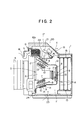
- a television camera has a camera body 1 defining a chamber 2, a three-plate image pickup device 3 received in the chamber 2, an optical lens 4 mounted on the front wall of the camera body 1, and a handle 5 attached to the upper wall of the camera body 1.
- the three-plate image pickup device 3 disposed in the front portion of the chamber 2 has a prism 6, three CCDs 7, i.e., solid-state imaging devices, respectively for red light, green light and blue light, fixedly attached to the three surfaces of the prism 6, respectively, and three wiring boards 8 disposed behind the three CCDs 7, respectively.
- the three CCDs 7 are connected to the three wiring boards 8 by wires, respectively.
- a heat radiating plate 11 is attached fixedly to the heat radiating side of each Peltier device 9.
- the three heat radiating places 11 are attached fixedly to three heat transfer places 13 included in a substantially U-shaped, heat radiating coil unit 12 covering the space behind the image pickup device 3.
- a plurality of printed wiring boards 14 provided with CCD driving circuits, signal processing circuits and the like are inserted in grooves formed in a pair of guides 15 and supported in a vertical position in the rear portion of the chamber 2.
- a partition wall 16 is extended in the upper end of the chamber 2 to form an air passage 17 for forced-air cooling, and an air inlet 18 for inflowing air b and an air outlet 19 for outflowing air c are formed in the camera body 1 respectively at the front and rear ends of the air passage 17.
- a fan 21 driven by a motor 20 is disposed in the air passage 17 at a position near the air outlet 19.
- An air outlet 22 is formed in the partition wall 16 at a position before the fan 21 with respect to the flowing direction of air, and air inlets 23 are formed in the bottom wall of the camera body 1.
- a heat radiating portion 12a formed at the upper end of the heat radiating coil unit 12 is inserted through the air outlet 22 in the air passage 17.
- the heat radiating coil unit 12 is formed by coiling a flexible, small tube 12c of a highly heat-conductive material, such as aluminum or copper, having a diameter in the range of about 1 mm to about 4 mm in closely arranged loops, and bending the closely arranged loops substantially in a U-shape in side view.
- the three heat transfer plates 13 formed of a highly heat-conductive material, such as copper, are attached adhesively or by suitable means respectively to the three heat transfer portions 12b of the heat radiating coil unit 12.
- a working fluid that conveys heat from the heat transfer portions 12b to the heat radiating portion 12a is sealed in the small pipe 12c to make the heat radiating coil unit 12 function like a heat pipe.
- the working fluid conveys heat by the propagation and axial vibrations of pressure waves produce by nucleate boiling corresponding to the quantity of heat transferred thereto through the heat transfer portions 12b.
- the heat radiating coil unit 12 is capable of conducting heat at a very high efficiency. Appropriate gaps G are formed between the adjacent loops of the small tube 12c in the heat radiating portion 12a to make the portions of the loops of the small tube 12c in the heat radiating portion 12a serve as heat radiating fins.
- a support plate 24 adhesively attached to the lower end of the heat radiating coil unit 12 is fastened to the inner surface of the front wall of the camera body 1.
- the buffering heat conducting mechanism 10 interconnecting the CCD 7 and the Peltier device 9 comprises a cylinder 26, a piston 27 slidably fitted in the cylinder 26 and having a head wall 27a having a spherical surface 28 having its centre on the axis of the piston 27, a swivel spacer 29 having a concave contact surface of a shape conforming to the spherical surface 28 of the piston 27, disposed with the concave contact surface thereof in close contact with the spherical surface 28 of the piston 27 and capable of sliding along the spherical surface 28 of the piston in directions as indicated by the arrows a, and a compression coil spring 30 compressed between the bottom wall 26a of the cylinder 26 and the head wall 27a of the piston 27 to press the piston 27 against the swivel spacer 29 so that the flat front surface 29a of the swivel spacer 29 is pressed closely against the flat back surface 7a of the CCD 7.
- the cylinder 26, the piston 27 and the swivel spacer 29 are formed of a highly heat-conductive material, such as aluminum, and the circumferential surface 31 of the piston 27 in sliding contact with the cylinder 26, and the spherical surface 28 of the piston 27 in sliding contact with the swivel spacer 29 are lubricated with a highly heat-conductive grease, such as silicone grease.
- the cylinder 26 and the swivel spacer 29 are covered with a cover 32 formed of an insulating material, such as a glassfibre reinforced plastic.
- the Peltierde- vice 9 is fitted in the centre hole 32b of the flange 32a of the cover 32 with its heat absorbing surface 9a in contact with the flat bottom wall 27a of the cylinder 26.
- the heat radiating plate 11 is fastened to the flange 32a with screws 33 so as to be in close contact with the heat radiating surface 9b of the Peltier device 9 so that the Peltier device 9 is held between the bottom wall 26a of the cylinder 26 and the heat radiating plate 11.
- Washers 34 formed of an insulating glassfibre reinforced plastic or the like are interposed between the heads of the screws 33 and the heat radiating plate 11.
- the heat radiating plate 11 is fastened to a heat conducting plate 13 attached to the heat radiating coil unit 12 with screws, not shown.
- the swivel spacer 29 is able to slide on the spherical surface 28 of the piston 27 in any direction so that the flat front surface thereof is in close contact with the back surface 7a of the CCD 7 when pressing the swivel spacer 29 against the flat back surface 7a of the CCD 7 through the piston 27 by the compression coil spring 30 of the buffering heat conducting mechanism 10. Accordingly, the flat front surface 29a of the swivel spacer 29 can be put in close contact with the flat back surface 7a of the CCD 7 without inducing mechanical stress in the CCD 7, even if the Peltier device 9 is inclined relative to the CCD 7.
- the thermal resistance between the heat absorbing surface 9a of the Peltier device 9 and the CCD is reduced to enable efficient transfer of heat by conduction from the CCD 7 to the Peltier device 9.
- the buffering heat conducting mechanism 10 Since the piston 27 is fitted slidably in the cylinder 26, the swivel spacer 29 is put in sliding contact with the spherical surface 28 of the piston 27 and the swivel spacer 29 need not be supported on shafts perpendicularly intersecting each other to enable the swivel spacer 29 move in optional directions, the buffering heat conducting mechanism 10 has a simple construction and can be easily fabricated.
- heat generated by the three CCD 7 is transferred by conduction through the three Peltier devices 9, the three heat radiating places 11 contiguous with the three Peltierde- vices 9 and the three heat conducting places 13 to the heat transfer portions of the heat radiating coil unit 12, and then the heat is conveyed by the working fluid sealed in the heat radiating coil unit 12 to the heat radiating portion 12a disposed in the air passage 17.
- the ambient air is sucked through the air inlet 18 into the air passage 17 in the direction of the arrow b by suction generated by fan 21 driven by the motor 20, the ambient air is caused to flow through the gaps G between the portions of the loops in the heat radiating portion 12a in the direction of the arrow c for the forced-air cooling of the heat radiating portion 12a, and to flow outside through the air outlet 19.
- heat can be efficiently removed from the heat radiating portion 12a.
- the three CCD 7 can be efficiently cooled by efficiently and uniformly removing heat from the three Peltier device 9 by the heat radiating coil unit 12.
- the heat radiating coil unit 12 is flexible, the heat radiating coil unit 12 can be easily installed in a narrow space. Since the heat radiating coil unit 12 conveys heat from the heat transfer portions 12b to the heat radiating portion 12a by the propagation and axial vibration of the pressure waves produced by the nucleate boiling of the working fluid sealed in the heat radiating coil unit 12, the performance of the heat radiating coil unit 12 is scarcely subject to the position of the television camera and has a simple, lightweight construction.
- the air outlet 22 of the chamber 2 opens into the air passage 17 at a position before the fan 21 with respect to the flowing direction of air, the warm air prevailing in the chamber2 can be sucked through the air outlet 22 into the air passage 17 as indicated by the arrow d in Fig. 2 and the ambient air can be sucked through the air inlets 23 into the chamber 2.
- the fan 21 achieves the forced cooling of the heat radiating portion 12a and the force exhaustion of the warm air prevailing in the chamber 2 simultaneously, whereby the chamber 2 is ventilated efficiently, and the three CCDs 7 and the wiring boards 14 can be efficiently cooled.
- the swivel spacer can be set in close contact with the hot component without inducing mechanical stress in the hot component, i.e., the CCD, even if the electronic cooling device, i.e., the Peltier device, is not disposed at a correct position in a correct position relative to the hot component, because the buffering heat conducting mechanism allows to conform to the position of the hot component.
- the electronic cooling device i.e., the Peltier device
- the buffering heat conducting mechanism is assembled by slidably fitting the piston in the cylinder and slidably putting the swivel spacer on the spherical surface of the piston, and the cylinder, the piston and the swivel spacer are put accurately into contact with each other, the thermal resistance between the electronic cooling device and the hot component can be reduced for efficient heat transfer from the hot component to the electronic cooling device.
- the buffering heat conducting mechanism need not be provided with any shafts for supporting the swivel spacer, the buffering heat conducting mechanism has a simple construction and can be easily fabricated.
- the fan sucks the ambient air forcibly into the air passage and discharges the ambient air forcibly for the forced-air cooling of the heat radiating portion of the heat radiating coil unit, heat of the heat conducting components can be efficiently dissipated.
- the fan functions for both the forced cooling of the heat radiating portion of the heat radiating coil unit in the air passage and the forced exhaustion of the warm air from the chamber containing the hot components, the chamber can be efficiently ventilated and the hot components can be efficiently cooled.
- the heat radiating coil unit is formed by coiling a flexible, small tube of a highly heat conductive material and sealing the working fluid in the flexible, small tube, the performance of the heat radiating coil unit is scarcely subject to the position of the electronic apparatus, i.e., the television camera, the hot components can be efficiently cooled, and the flexible heat radiating coil unit can be easily installed in a narrow space.
Landscapes
- Engineering & Computer Science (AREA)
- Multimedia (AREA)
- Signal Processing (AREA)
- Theoretical Computer Science (AREA)
- General Engineering & Computer Science (AREA)
- Physics & Mathematics (AREA)
- Thermal Sciences (AREA)
- Mechanical Engineering (AREA)
- Sustainable Development (AREA)
- Human Computer Interaction (AREA)
- General Physics & Mathematics (AREA)
- Life Sciences & Earth Sciences (AREA)
- Studio Devices (AREA)
- Cooling Or The Like Of Electrical Apparatus (AREA)
- Transforming Light Signals Into Electric Signals (AREA)
Applications Claiming Priority (2)
| Application Number | Priority Date | Filing Date | Title |
|---|---|---|---|
| JP11668992A JP3284585B2 (ja) | 1992-04-10 | 1992-04-10 | 電子機器の冷却装置 |
| JP116689/92 | 1992-04-10 |
Publications (3)
| Publication Number | Publication Date |
|---|---|
| EP0565366A2 true EP0565366A2 (de) | 1993-10-13 |
| EP0565366A3 EP0565366A3 (de) | 1995-02-22 |
| EP0565366B1 EP0565366B1 (de) | 1997-06-18 |
Family
ID=14693432
Family Applications (1)
| Application Number | Title | Priority Date | Filing Date |
|---|---|---|---|
| EP93302740A Expired - Lifetime EP0565366B1 (de) | 1992-04-10 | 1993-04-07 | Kühlungssystem zur Kühlung von elektronischen Vorrichtungen |
Country Status (4)
| Country | Link |
|---|---|
| US (1) | US5332031A (de) |
| EP (1) | EP0565366B1 (de) |
| JP (1) | JP3284585B2 (de) |
| DE (1) | DE69311615T2 (de) |
Cited By (7)
| Publication number | Priority date | Publication date | Assignee | Title |
|---|---|---|---|---|
| WO1998011715A1 (de) * | 1996-09-13 | 1998-03-19 | Leica Camera Ag | Kamera |
| EP1045452A4 (de) * | 1997-11-19 | 2000-12-06 | Hamamatsu Photonics Kk | PHOTODETEKTOR UND BIéDAUFNAHMEVORRICHTUNG DIE DIESEN PHOTODETEKTO R VERWENDET |
| US6628510B2 (en) * | 2001-09-06 | 2003-09-30 | First Capital International, Inc. | Method and apparatus for computer integral with wall |
| FR2860368A1 (fr) * | 2003-09-25 | 2005-04-01 | Omwave Sas | Appareil central de gestion de fonctions audio, video, et pc |
| EP1748640A1 (de) * | 2005-07-27 | 2007-01-31 | Sony Corporation | Kamera |
| CN102243416A (zh) * | 2010-03-30 | 2011-11-16 | 佳能株式会社 | 包括作为发热源的电子部件的电子设备 |
| EP2493173A1 (de) * | 2011-02-28 | 2012-08-29 | Panasonic Corporation | Kamerakopf und Kameravorrichtung |
Families Citing this family (23)
| Publication number | Priority date | Publication date | Assignee | Title |
|---|---|---|---|---|
| US5981933A (en) * | 1997-08-26 | 1999-11-09 | Dalsa, Inc. | CCD sensor with diagonal heat conducting straps |
| US6847403B1 (en) * | 1997-11-05 | 2005-01-25 | Polycom, Inc. | Integrated portable videoconferencing unit |
| JPH11345956A (ja) * | 1998-03-16 | 1999-12-14 | Canon Inc | 撮像装置 |
| FI108962B (fi) * | 1999-08-20 | 2002-04-30 | Nokia Corp | Laitekaapin jäähdytysjärjestelmä |
| AU2003298884A1 (en) * | 2002-12-04 | 2004-06-23 | Applied Precision, Llc | Thermally efficient ccd camera housing |
| JP2008130702A (ja) * | 2006-11-20 | 2008-06-05 | Furukawa Electric Co Ltd:The | ジョイント付ヒートシンク |
| US7554068B2 (en) | 2007-02-09 | 2009-06-30 | Panasonic Corporation | Heat radiating structure for solid-state image sensor, and solid-state image pickup device |
| JP4872091B2 (ja) * | 2007-06-05 | 2012-02-08 | 株式会社シーアイエス | 撮像装置 |
| JP4795307B2 (ja) * | 2007-06-08 | 2011-10-19 | 古河電気工業株式会社 | 放熱構造体 |
| JP2015039044A (ja) * | 2008-10-23 | 2015-02-26 | 株式会社東芝 | 撮像装置 |
| US20100242523A1 (en) * | 2009-03-31 | 2010-09-30 | Todd Rubright | Electric Cooling System for Electronic Equipment |
| CN103026699A (zh) * | 2011-07-26 | 2013-04-03 | 松下电器产业株式会社 | 摄像装置 |
| JP5896650B2 (ja) * | 2011-08-31 | 2016-03-30 | オリンパス株式会社 | 撮像装置 |
| EP2755073A4 (de) * | 2011-09-06 | 2015-04-15 | Fujifilm Corp | Fernsehlinsenvorrichtung |
| CN104471923A (zh) * | 2012-04-13 | 2015-03-25 | 黑魔法设计私人有限公司 | 相机 |
| DE102013218095A1 (de) * | 2013-09-10 | 2015-03-12 | Arnold & Richter Cine Technik Gmbh & Co. Betriebs Kg | Elektronische Bewegtbildkamera |
| TWI685638B (zh) * | 2018-09-14 | 2020-02-21 | 財團法人工業技術研究院 | 立體脈衝式熱管、立體脈衝式熱管組和散熱模組 |
| US10917544B2 (en) * | 2019-04-30 | 2021-02-09 | Gopro, Inc. | Heat transfer between integrated sensor-lens assemblies in an image capture device |
| EP3869779B1 (de) * | 2020-02-18 | 2022-04-13 | Axis AB | Überwachungskamera mit einem heizer |
| CN115379079B (zh) * | 2021-05-21 | 2024-06-28 | 杭州海康威视数字技术股份有限公司 | 摄像机 |
| CN113375027B (zh) * | 2021-07-12 | 2022-03-22 | 深圳市汇通四海科技有限公司 | 一种云台旋转光学变焦人脸识别的监控球机 |
| JP2023021774A (ja) | 2021-08-02 | 2023-02-14 | パナソニックIpマネジメント株式会社 | 撮像装置 |
| US11911790B2 (en) | 2022-02-25 | 2024-02-27 | Saudi Arabian Oil Company | Applying corrosion inhibitor within tubulars |
Family Cites Families (7)
| Publication number | Priority date | Publication date | Assignee | Title |
|---|---|---|---|---|
| US4314449A (en) * | 1978-12-06 | 1982-02-09 | Ford Aerospace & Communications Corp. | Non-contacting thermal energy transfer assembly |
| JPS5722070A (en) * | 1980-07-15 | 1982-02-04 | Oki Electric Ind Co Ltd | Cooling device for printer |
| GB2146865A (en) * | 1983-09-16 | 1985-04-24 | Rca Corp | Camera with reduced condensation cooled solid-state imager |
| JPS61113265A (ja) * | 1984-11-08 | 1986-05-31 | Mitsubishi Electric Corp | 半導体素子等の冷却装置 |
| JPH063354B2 (ja) * | 1987-06-23 | 1994-01-12 | アクトロニクス株式会社 | ル−プ型細管ヒ−トパイプ |
| US5040381A (en) * | 1990-04-19 | 1991-08-20 | Prime Computer, Inc. | Apparatus for cooling circuits |
| JP2859927B2 (ja) * | 1990-05-16 | 1999-02-24 | 株式会社東芝 | 冷却装置および温度制御装置 |
-
1992
- 1992-04-10 JP JP11668992A patent/JP3284585B2/ja not_active Expired - Fee Related
-
1993
- 1993-04-06 US US08/042,783 patent/US5332031A/en not_active Expired - Fee Related
- 1993-04-07 EP EP93302740A patent/EP0565366B1/de not_active Expired - Lifetime
- 1993-04-07 DE DE69311615T patent/DE69311615T2/de not_active Expired - Fee Related
Cited By (9)
| Publication number | Priority date | Publication date | Assignee | Title |
|---|---|---|---|---|
| WO1998011715A1 (de) * | 1996-09-13 | 1998-03-19 | Leica Camera Ag | Kamera |
| EP1045452A4 (de) * | 1997-11-19 | 2000-12-06 | Hamamatsu Photonics Kk | PHOTODETEKTOR UND BIéDAUFNAHMEVORRICHTUNG DIE DIESEN PHOTODETEKTO R VERWENDET |
| US6573640B1 (en) | 1997-11-19 | 2003-06-03 | Hamamatsu Photonics K.K. | Photodetecting device and image sensing apparatus using the same |
| US6628510B2 (en) * | 2001-09-06 | 2003-09-30 | First Capital International, Inc. | Method and apparatus for computer integral with wall |
| FR2860368A1 (fr) * | 2003-09-25 | 2005-04-01 | Omwave Sas | Appareil central de gestion de fonctions audio, video, et pc |
| EP1748640A1 (de) * | 2005-07-27 | 2007-01-31 | Sony Corporation | Kamera |
| CN102243416A (zh) * | 2010-03-30 | 2011-11-16 | 佳能株式会社 | 包括作为发热源的电子部件的电子设备 |
| EP2493173A1 (de) * | 2011-02-28 | 2012-08-29 | Panasonic Corporation | Kamerakopf und Kameravorrichtung |
| US8427572B2 (en) | 2011-02-28 | 2013-04-23 | Panasonic Corporation | Camera head and camera device |
Also Published As
| Publication number | Publication date |
|---|---|
| EP0565366A3 (de) | 1995-02-22 |
| DE69311615D1 (de) | 1997-07-24 |
| EP0565366B1 (de) | 1997-06-18 |
| JPH05292366A (ja) | 1993-11-05 |
| DE69311615T2 (de) | 1997-12-11 |
| US5332031A (en) | 1994-07-26 |
| JP3284585B2 (ja) | 2002-05-20 |
Similar Documents
| Publication | Publication Date | Title |
|---|---|---|
| US5332031A (en) | Cooling system for cooling a solid-state imaging device | |
| EP3187934B1 (de) | Bildaufnahmemodul | |
| US5813233A (en) | Thermoelectric cooling device and system thereof | |
| KR102067751B1 (ko) | 전자 디스플레이 장치의 열 제어 방법 및 시스템 | |
| JP2585003Y2 (ja) | 液晶プロジェクタの液晶冷却器 | |
| US6967841B1 (en) | Cooling assembly for electronics drawer using passive fluid loop and air-cooled cover | |
| EP1742263A2 (de) | Wärmesenke mit Zwangsdurchlaufsluftkühlung für ein Projektionsanzeigegerät | |
| JP5649369B2 (ja) | 電子機器 | |
| US11013148B2 (en) | Imaging apparatus | |
| EP1158389A3 (de) | Computer mit Kühleinrichtung und Wärmetauscher der Kühleinrichtung | |
| RU2002107437A (ru) | Электронное устройство с выделяющими тепло компонентами и поглощающими тепло элементами | |
| JP7091061B2 (ja) | 撮像装置 | |
| TWI799514B (zh) | 內視鏡攝影裝置以及內視鏡攝影系統 | |
| JPH11355623A (ja) | ビデオカメラの放熱装置 | |
| JPH07248480A (ja) | 液晶プロジェクタの冷却装置 | |
| JP4954625B2 (ja) | 監視カメラ | |
| JP6394386B2 (ja) | 冷凍装置 | |
| CN102075673A (zh) | 成像设备 | |
| CN215379068U (zh) | 一种双传感器相机 | |
| EP1523044A3 (de) | Bildaufnahmevorrichtung | |
| JP2003046828A (ja) | 電子カメラ | |
| JPH0546381Y2 (de) | ||
| KR0134755Y1 (ko) | 영상 표시 기기의 통기막 설치 구조 | |
| JP3459468B2 (ja) | 電子機器の冷却装置 | |
| US20190298162A1 (en) | Endoscopic device and heat radiator |
Legal Events
| Date | Code | Title | Description |
|---|---|---|---|
| PUAI | Public reference made under article 153(3) epc to a published international application that has entered the european phase |
Free format text: ORIGINAL CODE: 0009012 |
|
| AK | Designated contracting states |
Kind code of ref document: A2 Designated state(s): DE FR GB |
|
| PUAL | Search report despatched |
Free format text: ORIGINAL CODE: 0009013 |
|
| AK | Designated contracting states |
Kind code of ref document: A3 Designated state(s): DE FR GB |
|
| 17P | Request for examination filed |
Effective date: 19950703 |
|
| 17Q | First examination report despatched |
Effective date: 19951006 |
|
| GRAG | Despatch of communication of intention to grant |
Free format text: ORIGINAL CODE: EPIDOS AGRA |
|
| GRAH | Despatch of communication of intention to grant a patent |
Free format text: ORIGINAL CODE: EPIDOS IGRA |
|
| GRAH | Despatch of communication of intention to grant a patent |
Free format text: ORIGINAL CODE: EPIDOS IGRA |
|
| GRAA | (expected) grant |
Free format text: ORIGINAL CODE: 0009210 |
|
| AK | Designated contracting states |
Kind code of ref document: B1 Designated state(s): DE FR GB |
|
| REF | Corresponds to: |
Ref document number: 69311615 Country of ref document: DE Date of ref document: 19970724 |
|
| ET | Fr: translation filed | ||
| PLBE | No opposition filed within time limit |
Free format text: ORIGINAL CODE: 0009261 |
|
| STAA | Information on the status of an ep patent application or granted ep patent |
Free format text: STATUS: NO OPPOSITION FILED WITHIN TIME LIMIT |
|
| 26N | No opposition filed | ||
| REG | Reference to a national code |
Ref country code: GB Ref legal event code: IF02 |
|
| PGFP | Annual fee paid to national office [announced via postgrant information from national office to epo] |
Ref country code: GB Payment date: 20030402 Year of fee payment: 11 |
|
| PGFP | Annual fee paid to national office [announced via postgrant information from national office to epo] |
Ref country code: FR Payment date: 20030408 Year of fee payment: 11 |
|
| PGFP | Annual fee paid to national office [announced via postgrant information from national office to epo] |
Ref country code: DE Payment date: 20030417 Year of fee payment: 11 |
|
| PG25 | Lapsed in a contracting state [announced via postgrant information from national office to epo] |
Ref country code: GB Free format text: LAPSE BECAUSE OF NON-PAYMENT OF DUE FEES Effective date: 20040407 |
|
| PG25 | Lapsed in a contracting state [announced via postgrant information from national office to epo] |
Ref country code: DE Free format text: LAPSE BECAUSE OF NON-PAYMENT OF DUE FEES Effective date: 20041103 |
|
| GBPC | Gb: european patent ceased through non-payment of renewal fee | ||
| PG25 | Lapsed in a contracting state [announced via postgrant information from national office to epo] |
Ref country code: FR Free format text: LAPSE BECAUSE OF NON-PAYMENT OF DUE FEES Effective date: 20041231 |
|
| REG | Reference to a national code |
Ref country code: FR Ref legal event code: ST |