EP0562073B1 - Feststell- und verriegelungseinheit - Google Patents
Feststell- und verriegelungseinheit Download PDFInfo
- Publication number
- EP0562073B1 EP0562073B1 EP92920220A EP92920220A EP0562073B1 EP 0562073 B1 EP0562073 B1 EP 0562073B1 EP 92920220 A EP92920220 A EP 92920220A EP 92920220 A EP92920220 A EP 92920220A EP 0562073 B1 EP0562073 B1 EP 0562073B1
- Authority
- EP
- European Patent Office
- Prior art keywords
- locking
- securing
- locking unit
- screw
- unit according
- Prior art date
- Legal status (The legal status is an assumption and is not a legal conclusion. Google has not performed a legal analysis and makes no representation as to the accuracy of the status listed.)
- Expired - Lifetime
Links
- 239000002184 metal Substances 0.000 claims description 2
- 238000005192 partition Methods 0.000 abstract 1
- 238000004519 manufacturing process Methods 0.000 description 5
- 238000000034 method Methods 0.000 description 4
- 239000000725 suspension Substances 0.000 description 3
- 238000010276 construction Methods 0.000 description 2
- 238000006073 displacement reaction Methods 0.000 description 2
- 239000011521 glass Substances 0.000 description 2
- 238000003780 insertion Methods 0.000 description 2
- 230000037431 insertion Effects 0.000 description 2
- 238000003801 milling Methods 0.000 description 2
- 239000004020 conductor Substances 0.000 description 1
- 238000009434 installation Methods 0.000 description 1
- 239000000463 material Substances 0.000 description 1
Images

Classifications
-
- E—FIXED CONSTRUCTIONS
- E05—LOCKS; KEYS; WINDOW OR DOOR FITTINGS; SAFES
- E05D—HINGES OR SUSPENSION DEVICES FOR DOORS, WINDOWS OR WINGS
- E05D15/00—Suspension arrangements for wings
- E05D15/48—Suspension arrangements for wings allowing alternative movements
-
- E—FIXED CONSTRUCTIONS
- E04—BUILDING
- E04B—GENERAL BUILDING CONSTRUCTIONS; WALLS, e.g. PARTITIONS; ROOFS; FLOORS; CEILINGS; INSULATION OR OTHER PROTECTION OF BUILDINGS
- E04B2/00—Walls, e.g. partitions, for buildings; Wall construction with regard to insulation; Connections specially adapted to walls
- E04B2/74—Removable non-load-bearing partitions; Partitions with a free upper edge
- E04B2/82—Removable non-load-bearing partitions; Partitions with a free upper edge characterised by the manner in which edges are connected to the building; Means therefor; Special details of easily-removable partitions as far as related to the connection with other parts of the building
- E04B2/827—Partitions constituted of sliding panels
-
- E—FIXED CONSTRUCTIONS
- E05—LOCKS; KEYS; WINDOW OR DOOR FITTINGS; SAFES
- E05B—LOCKS; ACCESSORIES THEREFOR; HANDCUFFS
- E05B65/00—Locks or fastenings for special use
- E05B65/08—Locks or fastenings for special use for sliding wings
- E05B65/087—Locks or fastenings for special use for sliding wings the bolts sliding parallel to the wings
- E05B65/0876—Locks or fastenings for special use for sliding wings the bolts sliding parallel to the wings cooperating with the slide guide, e.g. the rail
-
- E—FIXED CONSTRUCTIONS
- E05—LOCKS; KEYS; WINDOW OR DOOR FITTINGS; SAFES
- E05C—BOLTS OR FASTENING DEVICES FOR WINGS, SPECIALLY FOR DOORS OR WINDOWS
- E05C5/00—Fastening devices with bolts moving otherwise than only rectilinearly and only pivotally or rotatively
- E05C5/02—Fastening devices with bolts moving otherwise than only rectilinearly and only pivotally or rotatively both moving axially and turning about their axis to secure the wing
- E05C5/04—Fastening devices with bolts moving otherwise than only rectilinearly and only pivotally or rotatively both moving axially and turning about their axis to secure the wing performing both movements simultaneously, e.g. screwing into a keeper
-
- E—FIXED CONSTRUCTIONS
- E05—LOCKS; KEYS; WINDOW OR DOOR FITTINGS; SAFES
- E05D—HINGES OR SUSPENSION DEVICES FOR DOORS, WINDOWS OR WINGS
- E05D15/00—Suspension arrangements for wings
- E05D15/06—Suspension arrangements for wings for wings sliding horizontally more or less in their own plane
- E05D15/0604—Suspension arrangements for wings for wings sliding horizontally more or less in their own plane allowing an additional movement
- E05D15/0608—Suspension arrangements for wings for wings sliding horizontally more or less in their own plane allowing an additional movement caused by track lay-out
- E05D15/0613—Suspension arrangements for wings for wings sliding horizontally more or less in their own plane allowing an additional movement caused by track lay-out with multi-directional trolleys
-
- E—FIXED CONSTRUCTIONS
- E05—LOCKS; KEYS; WINDOW OR DOOR FITTINGS; SAFES
- E05D—HINGES OR SUSPENSION DEVICES FOR DOORS, WINDOWS OR WINGS
- E05D15/00—Suspension arrangements for wings
- E05D15/06—Suspension arrangements for wings for wings sliding horizontally more or less in their own plane
- E05D15/0604—Suspension arrangements for wings for wings sliding horizontally more or less in their own plane allowing an additional movement
-
- E—FIXED CONSTRUCTIONS
- E05—LOCKS; KEYS; WINDOW OR DOOR FITTINGS; SAFES
- E05D—HINGES OR SUSPENSION DEVICES FOR DOORS, WINDOWS OR WINGS
- E05D15/00—Suspension arrangements for wings
- E05D15/56—Suspension arrangements for wings with successive different movements
- E05D15/58—Suspension arrangements for wings with successive different movements with both swinging and sliding movements
-
- E—FIXED CONSTRUCTIONS
- E05—LOCKS; KEYS; WINDOW OR DOOR FITTINGS; SAFES
- E05D—HINGES OR SUSPENSION DEVICES FOR DOORS, WINDOWS OR WINGS
- E05D15/00—Suspension arrangements for wings
- E05D15/48—Suspension arrangements for wings allowing alternative movements
- E05D2015/485—Swinging or sliding movements
-
- E—FIXED CONSTRUCTIONS
- E05—LOCKS; KEYS; WINDOW OR DOOR FITTINGS; SAFES
- E05Y—INDEXING SCHEME ASSOCIATED WITH SUBCLASSES E05D AND E05F, RELATING TO CONSTRUCTION ELEMENTS, ELECTRIC CONTROL, POWER SUPPLY, POWER SIGNAL OR TRANSMISSION, USER INTERFACES, MOUNTING OR COUPLING, DETAILS, ACCESSORIES, AUXILIARY OPERATIONS NOT OTHERWISE PROVIDED FOR, APPLICATION THEREOF
- E05Y2201/00—Constructional elements; Accessories therefor
- E05Y2201/20—Brakes; Disengaging means; Holders; Stops; Valves; Accessories therefor
- E05Y2201/218—Holders
- E05Y2201/22—Locks
-
- E—FIXED CONSTRUCTIONS
- E05—LOCKS; KEYS; WINDOW OR DOOR FITTINGS; SAFES
- E05Y—INDEXING SCHEME ASSOCIATED WITH SUBCLASSES E05D AND E05F, RELATING TO CONSTRUCTION ELEMENTS, ELECTRIC CONTROL, POWER SUPPLY, POWER SIGNAL OR TRANSMISSION, USER INTERFACES, MOUNTING OR COUPLING, DETAILS, ACCESSORIES, AUXILIARY OPERATIONS NOT OTHERWISE PROVIDED FOR, APPLICATION THEREOF
- E05Y2600/00—Mounting or coupling arrangements for elements provided for in this subclass
- E05Y2600/60—Mounting or coupling members; Accessories therefor
- E05Y2600/62—Bolts
-
- E—FIXED CONSTRUCTIONS
- E05—LOCKS; KEYS; WINDOW OR DOOR FITTINGS; SAFES
- E05Y—INDEXING SCHEME ASSOCIATED WITH SUBCLASSES E05D AND E05F, RELATING TO CONSTRUCTION ELEMENTS, ELECTRIC CONTROL, POWER SUPPLY, POWER SIGNAL OR TRANSMISSION, USER INTERFACES, MOUNTING OR COUPLING, DETAILS, ACCESSORIES, AUXILIARY OPERATIONS NOT OTHERWISE PROVIDED FOR, APPLICATION THEREOF
- E05Y2800/00—Details, accessories and auxiliary operations not otherwise provided for
- E05Y2800/20—Combinations of elements
- E05Y2800/22—Combinations of elements of not identical elements of the same category, e.g. combinations of not identical springs
-
- E—FIXED CONSTRUCTIONS
- E05—LOCKS; KEYS; WINDOW OR DOOR FITTINGS; SAFES
- E05Y—INDEXING SCHEME ASSOCIATED WITH SUBCLASSES E05D AND E05F, RELATING TO CONSTRUCTION ELEMENTS, ELECTRIC CONTROL, POWER SUPPLY, POWER SIGNAL OR TRANSMISSION, USER INTERFACES, MOUNTING OR COUPLING, DETAILS, ACCESSORIES, AUXILIARY OPERATIONS NOT OTHERWISE PROVIDED FOR, APPLICATION THEREOF
- E05Y2900/00—Application of doors, windows, wings or fittings thereof
- E05Y2900/10—Application of doors, windows, wings or fittings thereof for buildings or parts thereof
- E05Y2900/13—Type of wing
- E05Y2900/142—Partition walls
Definitions
- the invention relates to a locking and locking unit according to the preamble of claim A.
- the system consists of fixed ceiling rails with corresponding rail branches, which allow parts or the entire unit arranged underneath to be moved or parked in a side position. This always happens cann, e.g. a room is divided or a room is to be divided into several smaller rooms.
- Another area of application today is increasingly door wall elements in the catering and business sectors. Depending on the weather, the entire window front can be removed here, or only parts of this entire system can be moved.
- the object of the invention is to provide a locking and locking unit, the two functions of which, namely oscillating and moving, are combined in one unit.
- the handling must be simple and the assembly must be able to be carried out on existing doors, with a restriction to very specific door types not being intended.
- the manufacturing aspect of creating an inexpensive locking device must not be overlooked.
- a locking device consisting of an upper part, middle part and lower part, which are placed one below the other, being created.
- These three parts of the unit are attached to the outside of the door system using fastening screws. There is one screw for the locking and one for the locking process within the unit. These screws are operated from the ground with the help of an articulated crank, which has a hexagon socket wrench at its upper end. Using this hexagon socket wrench, both the locking and locking screws can be screwed in or out.
- the locking screw which is located in the central part of the unit, is screwed into the upper part of the unit, which is fastened to the running rail, by means of a rotary movement.
- part of the unit namely the upper and lower part, is connected to one another and the wing can no longer be moved laterally.
- the second locking screw which is located in the lower part of the unit, must be screwed into the central part of the unit. This type of screw connection fixes the entire door, the upper, middle and lower part form one unit.
- the locking connection must be released accordingly and the entire leaf can be moved within the running rail. If, however, only a swinging of the door is desired, the connection of the locking screw with the running rail must be maintained, and the locking screw is unscrewed from the middle part and the door is no longer fixed in its swivel range. Due to the articulated crank used, the hazard potential when adjusting the locking and locking is practically reduced to zero because no additional devices have to be used.
- the inventive idea creates a hold-open locking unit that can also be easily installed on existing door systems.
- the entire unit is connected to the door system by means of six connecting screws. This is a quick installation method and can therefore also be carried out on existing door systems without complex milling work realize.
- This hold-open locking unit does not require any complex manufacturing processes in production either.
- a lock (2) can be attached to the door near the floor, which can be used to lock the door as a whole.
- FIG. 2 shows a section of an overall system in which several door elements or wall elements are indicated schematically. These wall and door elements can be designed both as all-glass or as a frame element.
- the locking and locking unit (5) is shown here in a position in which the locking screw (19) is connected to the upper part (10) via the central part (12). This makes it clear that the upper part (10) is connected to the running rail (6) via the connections (11) that it is no longer possible to move the door (1).
- the locking screw (24) is shown in a position in which it is only in the lower part (33) of the locking and locking unit (5).
- This swivel range is ever but limited to one side by the stop (7), which only allows the door to swing open in one direction.
- a door closer (8) which is also attached to the cover profile (36) of the door leaf (1), on which the lower part (33) of the locking and locking unit (5) is also located.
- FIG. 3 provides an overall overview with the locking and locking unit, which is partly shown in section.
- the upper part of the locking and locking unit (5) is connected to the running rail (6) fastened to the ceiling or to the fixed frame of the entire system by means of the running rail fastenings (11).
- the locking screw (19) is turned via the thread (15) in the central part (12) with the cylindrical shaft (39) into the bushing (17) of the blind bore (16) of the upper part (10). So that the screwing in can be carried out better and the manufacturing tolerances of the entire system can also be compensated for, the locking screw (19) is equipped with a conical chamfer (30) at its beginning. This conical chamfer (30) enables a better insertion of the locking screw (19) into the bushing (17) of the material bore (16). In this position shown, the door (1) cannot be moved, since the connection to the fixed part of the running rail (6) via the upper part (10) of the locking and locking unit (5) was established by the locking screw (19).
- the lower part (33) is in alignment below the middle part (12).
- the lower part (33) is connected to the cover profile (36), which is located on the door leaf (1) of the all-glass door, via the frame fastening (22).
- the locking screw (19) there is another adjustable screw, namely the locking screw (24) in the locking and locking unit (5).
- Another hole (32) has been made in the central part (12) parallel to the hole (20) for the locking screw (19).
- This bore (32) represents a blind bore in the central part, the beginning of which, however, lies flush with the bore (38) with the lower part (33) underneath.
- the bore (32) has an internal thread (31) in its rear part. In order to avoid the pendulum movement of the door, the locking screw (24) with its external thread (26) can be screwed into this internal thread (31).
- This locking screw (24) also has a conical chamfer (29) at its beginning, which also ensures secure insertion into the blind bore (32).
- the locking screw (24) has in its rear part towards the stop head (28) an undercut (27) of the thread (26), which enables a better screwing in.
- the locking screw (24) is inserted into the central part via the hexagon socket (23) in its head with the hand crank and the Allen key attached to it (12) screwed in.
- the stop is formed by the stop head (28), which goes into the lower part (33). This connection of the middle part (12) with the lower part (33) prevents the pendulum movement of the door. If all three individual parts of the locking and locking unit (5) are connected to each other using the locking screw (19) and locking screw (24), the door can no longer move. This ensures that the door has been locked and locked in a simple manner.
- FIG. 4 the side view in section is clearly shown once again that the parts of the door that are not firmly connected to one another can be securely connected to one another both for the pivoting process and for the displacement process by means of the locking and locking unit (5).
- An adjustable stop (34) is located between the middle part (12) and the lower part (33) so that when the locking screw (24) is tightened the door or the lower part (33) does not tilt with the middle part (12).
- This stop (34) can preferably be made of plastic and, by means of appropriate precautions, compensate for the remaining air gap between the central part (12) and the lower part (33).
- the door cannot be moved in the state shown, since the locking screw (19) has entered into a connection with the upper part (10).
- the upper part (10) is in direct contact with the running rail (6) via the connection of the running rail fastening (11). As a result, the rollers in the running rail with the suspension (35) underneath can no longer move the door.
- the advantage of the invention lies in the fact that the locking and locking unit are quasi housed in one housing. This considerably simplifies handling for the operating personnel, since the same articulated crank is used for the locking or locking.
- the entire system can be reached from the ground using the articulated crank, which can be obtained in various lengths, which is a huge advantage if the door heights are well over 2 m.
- the entire locking and locking unit can also be subsequently screwed onto any type of door system because only six screw connections need to be connected to the existing door or wall system.
- the locking device is preferably made of light metal or a suitable plastic.
Landscapes
- Engineering & Computer Science (AREA)
- Mechanical Engineering (AREA)
- Architecture (AREA)
- Physics & Mathematics (AREA)
- Electromagnetism (AREA)
- Civil Engineering (AREA)
- Structural Engineering (AREA)
- Support Devices For Sliding Doors (AREA)
- Input Circuits Of Receivers And Coupling Of Receivers And Audio Equipment (AREA)
- Residential Or Office Buildings (AREA)
- Control Of Vending Devices And Auxiliary Devices For Vending Devices (AREA)
- Fittings On The Vehicle Exterior For Carrying Loads, And Devices For Holding Or Mounting Articles (AREA)
- Walking Sticks, Umbrellas, And Fans (AREA)
- Preparation Of Clay, And Manufacture Of Mixtures Containing Clay Or Cement (AREA)
- Lock And Its Accessories (AREA)
- Casings For Electric Apparatus (AREA)
- Door And Window Frames Mounted To Openings (AREA)
- Hooks, Suction Cups, And Attachment By Adhesive Means (AREA)
- Clamps And Clips (AREA)
Description
- Die Erfindung betrifft eine Feststell- und Verriegelungseinheit nach dem Oberbegriff des Anspruchs A. Dabei besteht das System aus festmontierten Deckenschienen mit entsprechenden Schienenverzweigungen, die es zulassen, Teile oder die gesamte darunter angeordnete Einheit zu verschieben oder in einer Seitenlage zu parken. Dieses geschieht immer cann, wenn z.B. ein Raum abgeteilt werden oder aber ein Raum in mehrere kleinere Räume aufgeteilt werden soll. Ein weiterer Anwendungsbereich sind heute in zunehmendem Maße Türwandelemente im Gaststätten- und Geschäftsbereich. Hier kann je nach Witterungslage die gesamte Fensterfront beseitigt werden, oder aber es können auch nur Teile dieser Gesamtanlage verschoben werden.
- Anlagen dieser Art sind aus der DE PS 35 22 824 sowie der DE PS 31 48 464 zu entnehmen. Um diese Anlagen jedoch schnell und ohne große Kraftaufwendung verändern zu können, sind die Tür- und Wandelemente mit sogenannten Feststellern, die sich am oberen Ende eines Elementes befinden und durch Herausnahme bzw. Hereinnahme einer Verriegelung gelöst oder festgestellt werden können, ausgerüstet. Dieses wird jedoch in dem Augenblick problematisch, wenn bei hohen Anlagen von über 2 m vom Boden aus gemessen nicht mehr jede Person diese Verriegelung ohne Zuhilfenahme von Leitern oder dergleichen erreichen kann. Darüber hinaus befindet sich neben der Verriegelung auch noch ein Hakenriegelschloß, welches mit seinem Schließkloben eingerastet werden muß. Dieses Schloß ist in seiner Ausführung sehr aufwendig gestaltet und erforgert aufwendige Fräsarbeiten beim Einsetzen in die Türschiene. Auch ist die Handhabung dieses Schlosses nicht ganz unproblematisch, da sich in der Regel dieses Schloß auch am oberen Ende des Türblattes befindet.
- Es kann deshalb gesagt werden, daß die heute auf dem Markt zu findenden Anlagen nicht bedienerfreundlich sind und darüber hinaus in einem hohen Maße auch ein Gefahrenpotential beinhalten, da zur Bedienung in der Regel Hilfseinrichtungen wie Leitern usw. benutzt werden müssen. Ebenfalls ist die Konstruktionsart dieser Verriegelungen und Schlösser fertigungstechnisch sehr kostspielig.
- Die Aufgabe der Erfindung ist es, eine Feststell- und Verriegelungseinheit zu schaffen, deren beide Funktionen, nämlich Pendeln und Verschieben, in einer Einheit vereinigt sind. Darüber hinaus muß die Handhabung einfach vonstatten gehen können und die Montage muß an vorhandenen Türen durchgeführt werden können, wobei eine Einschränkung auf ganz bestimmte Türtypen nicht vorgesehen sein soll. Auch der fertigungstechnische Gesichtspunkt, eine preisgünstige Feststellverriegelungseinheit zu schaffen, darf nicht aus dem Auge gelassen werden.
- Die Aufgabe wird mittels den Kennzeichnenden Merkmalen des Anspruchs 1 gelöst, wobei eine Feststellverriegelungseinheit bestehend aus einem Oberteil, Mittelteil und Unterteil, welche untereinander plaziert sind, geschaffen wird. Diese drei Teile der Einheit werden außen auf der Türanlage mittels Befestigungsschrauben angebracht. Dabei befinden sich innerhalb der Einheit je eine Schraube für den Feststell- und für den Verriegelungsvorgang. Bedient werden diese Schrauben vom Boden aus mit Hilfe einer Gelenkkurbel, die an ihrem oberen Ende einen Kugelsechskantstiftschlüssel hat. Mittels dieses Kugelsechskantstiftschlüssels können sowohl die Feststell- als auch die Verriegelungsschrauben herein- oder herausgedreht werden.
- Wird beispielsweise davon ausgegangen, daß die Tür verschlossen ist, so wird die Feststellschraube, welche sich im Mittelteil der Einheit befindet, durch eine Drehbewegung in das darüber befindliche, an der Laufschiene befestigte Oberteil der Einheit geschraubt. Dadurch ist ein Teil der Einheit, nämlich Ober- und Unterteil, miteinander verbunden, und es läßt sich der Flügel nicht mehr seitlich verschieben. Damit auch die Pendellage gesichert werden kann, muß die zweite Verriegelungsschraube, welche sich im Unterteil der Einheit befindet, in das Mittelteil der Einheit geschraubt werden. Durch diese Verschraubungsart wird die gesamte Tür festgesetzt, Ober-, Mittel- und Unterteil bilden eine Einheit.
- Soll nun der Türflügel im Gesamten in eine Parkposition gebracht werden, so ist die Feststellverbindung entsprechend zu lösen und der gesamte Flügel läßt sich innerhalb der Laufschiene verschieben. Wird aber nur ein Pendeln der Tür erwünscht, so muß die Verbindung der Feststellschraube mit der Laufschiene erhalten bleiben, und es wird die Verriegelungsschraube aus dem Mittelteil herausgedreht und die Tür ist in ihrem Schwenkbereich nicht mehr festgesetzt. Auf Grund der verwendeten Gelenkkurbel wird das Gefahrenpotential bei der Verstellung der Verriegelung und Feststellung praktisch auf Null herabgesetzt, weil keine zusätzlichen Einrichtungen benutzt werden müssen.
- Auf Grund dieser Konstruktionsart schafft der erfinderische Gedanke eine Feststellverriegelungseinheit, die auch auf bestehende Türanlagen ohne weiteres montiert werden kann. Wie in dem nachfolgenden Ausführungsbeispiel später noch erläutert wird, wird die gesamte Einheit mittels sechs Verbindungsschrauben mit der Türanlage verbunden. Dieses ist eine schnelle Montageart und läßt sich somit auch an bestehenden Türanlagen ohne aufwendige Fräsarbeiten realisieren. Auch in der Herstellung bereitet diese Feststellverriegelungseinheit keine aufwendigen Herstellverfahren.
- Die Erfindung soll an einem möglichen, in den Zeichnungen schematisch dargestellten Ausführungsbeispiel näher erläutert werden.
- Es zeigt:
- Figur 1:
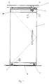
- Gesamttür mit Feststell- und Verriegelungseinheit
- Figur 2:
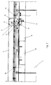
- Feststell- und Verriegelungseinheit in Verbindung mit einem Türschließer.
- Figur 3:
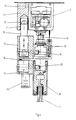
- Feststell- und Verriegelungseinheit, teilweise im Schnitt, an einer Tür montiert.
- Figur 4:
- montierte Feststell- und Verriegelungseinheit in der Seitenansicht im Schnitt dargestellt.
- Die Figur 1 zeigt eine Gesamttür, an die eine Feststell- und Verriegelungseinheit angebracht worden ist. Soll diese Einheit beispielsweise verschoben werden, so sind folgende Handgriffe zu tätigen:
- A. Die Verriegelungsschraube (24) muß hereingedreht werden, damit die Tür nicht mehr pendeln kann.
- B. Die Bodenarrettierung (4) muß herausgezogen werden, damit die Tür auch im Bodenbereich frei wird.
- C. Die Feststellschraube (19) ist auch mittels einer Gelenkkurbel herauszudrehen, so daß die Verbindung der Tür zur an der Decke befestigten Laufschiene (6) freigegeben wird. Auf Grund dieser Position der Schraubenstellungen kann die Tür über die Aufhängungen (35) in der Laufschiene verschoben werden.
- Soll diese Tür jedoch nicht mehr verschoben werden, so sind die vorbeschriebenen Handgriffe entsprechend umzukehren:
- C. Die Feststellschraube (19) muß wieder in ihre Arrettierungsposition mit der Laufschiene (6) gebracht werden.
- B. Danach kann die Bodenarrettierung (4) wieder verriegelt werden, und erst im 3. Schritt (A) kann dann die Verriegelungsschraube (24) herausgedreht werden.
- In dieser Stellung ist die Tür in der Lage, zu beiden Seiten zu pendeln, es sei denn, es ist ein Türschließer angebracht bzw. es befindet sich im oberen Bereich ein Anschlag (7), der den Schwenkbereich der Tür nur zu einer Richtung freigibt. Zusätzlich kann noch in Bodennähe in der Tür ein Schloß (2) angebracht werden, mit dem die Tür insgesamt verschlossen werden kann.
- Die Figur 2 zeigt einen Ausschnitt aus einer Gesamtanlage, bei der mehrere Türelemente bzw. Wandelemente schematisch angedeutet sind. Diese Wand- und Türelemente können sowohl als Ganzglas oder auch als Rahmenelement ausgebildet sein. Die Feststell- und Verriegelungseinheit (5) ist hier in einer Position gezeigt, in der die Feststellschraube (19) über das Mittelteil (12) mit dem Oberteil (10) verbunden ist. Hierdurch wird deutlich, weil das Oberteil (10) mit der Laufschiene (6) über die Verbindungen (11) verbunden ist, daß nun ein Verschieben der Tür (1) nicht mehr möglich ist.
- Dagegen wird die Verriegelungsschraube (24) in einer Position gezeigt, in der sie nur im Unterteil (33) der Feststell- und Verriegelungseinheit (5) sich befindet. Hierdurch ist es möglich, daß die Tür (1) in ihrem Schwenkbereich nicht behindert wird. Dieser Schwenkbereich ist je doch zu einer Seite begrenzt durch den Anschlag (7), der die Tür nur in einer Richtung aufschwenken läßt. Des weiteren befindet sich an diesem Ausführungsbeispiel ein Türschließer (8), der auch an dem Abdeckprofil (36) des Türblattes (1), an dem sich auch das Unterteil (33) der Feststell- und Verriegelungseinheit (5) befindet, angebracht ist.
- Einen Gesamtüberblick verschafft die Figur 3 mit der teilweise im Schnitt dargestellten Feststell- und Verriegelungseinheit. An der an der Decke oder auch am feststehenden Rahmen der Gesamtanlage befestigten Laufschiene (6) ist das Oberteil der Feststell- und Verriegelungseinheit (5) mittels der Laufschienenbefestigungen (11) verbunden. Die Feststellschraube (19) wird über das Gewinde (15) im Mittelteil (12) mit dem zylindrischen Schaft (39) in die Buchse (17) der Sackbohrung (16) des Oberteiles (10) gedreht. Damit das Einschrauben besser durchgeführt werden kann, und damit auch die Fertigungstoleranzen der Gesamtanlage ausgeglichen werden können, ist die Feststellschraube (19) an ihrem Anfang mit einem konischen Anschnitt (30) ausgestattet. Dieser konische Anschnitt (30) ermöglicht ein besseres Einführen der Feststellschraube (19) in die Buchse (17) der Sachbohrung (16). In dieser dargestellten Stellung ist die Tür (1) nicht verschiebbar, da durch die Feststellschraube (19) die Verbindung zum feststehenden Teil der Laufschiene (6) über das Oberteil (10) der Feststell- und Verriegelungseinheit (5) hergestellt wurde.
- Würde nun über den Innensechskant (14) der Feststellschraube (19) mittels der nicht dargestellten Gelenkkurbel die an ihrem Ende einen Kugelsechskantstiftschlüssel beinhaltet, die Feststellschraube (19) aus dem Gewinden (15) herausgedreht, so würde die Tür (1) zum Verschieben freigegeben. Damit die Feststellschraube (19) nicht aus der Bohrung herausfallen kann, befindet sich im Unterteil (33) der Feststellverriegelungseinheit (5) ein Anschlag (21). Dieser Anschlag (21) verhindert, daß die Feststellschraube (19) verloren gehen kann. Durch alle drei Teile der Feststell- und Verriegelungseinheit (5), nämlich dem Unterteil (33), Mittelteil (12) und Oberteil (10) führt eine fluchtende Bohrung (20), in der vertikal verstellbar die Feststellschraube (19) eingesetzt ist. Das Mittelteil (12) ist über die verbindungen der Befestigung (13) mit dem Laufwagenprofil (37) verbunden. Unterhalb des Mittelteiles (12) befindet sich in der Flucht das Unterteil (33). Das Unterteil (33) ist über die Rahmenbefestigung (22) mit dem Abdeckprofil (36), welches sich auf dem Türblatt (1) der Ganzglastür befindet, verbunden. Neben der Feststellschraube (19) befindet sich eine weitere verstellbare Schraube, nämlich die Verriegelungsschraube (24) in der Feststell- und Verriegelungseinheit (5). Parallel zur Bohrung (20) für die Feststellschraube (19) ist eine weitere Bohrung (32) im Mittelteil (12) eingebracht worden. Diese Bohrung (32) stellt im Mittelteil eine Sackbohrung dar, deren Anfang jedoch mit dem darunter liegenden Unterteil (33) in einer Flucht mit der Bohrung (38) liegt. Die Bohrung (32) hat in ihrem hinteren Teil ein Innengewinde (31). In dieses Innengewinde (31) kann zur Vermeidung der Pendelbewegung der Tür die Verriegelungsschraube (24) mit ihrem Außengewinde (26) eingedreht werden. Auch diese Verriegelungsschraube (24) hat an ihrem Anfang einen konischen Anschnitt (29), der ebenfalls ein sicheres Einführen in die Sackbohrung (32) gewährleistet. Jedoch hat die Verriegelungsschraube (24) in ihrem hinteren Teil zum Anschlagkopf (28) hin eine Hinterschneidung (27) des Gewindes (26), wodurch ein besseres Eindrehen möglich ist. Die Verriegelungsschraube (24) wird über den in ihrem Kopf befindlichen Innensechskant (23) mit der Handkurbel und dem daran befestigten Fugelsechskantstiftschlüssel in das Mittelteil (12) eingeschraubt. Den Anschlag bildet der Anschlagkopf (28), welcher in das Unterteil (33) hineingeht. Durch diese Verbindung des Mittelteiles (12) mit dem Unterteil (33) wird ein Verhindern der Pendelbewegung der Tür erreicht. Wenn alle drei Einzelteile der Feststell- und Verriegelungseinheit (5) mittels der Feststellschraube (19) und der Verriegelungsschraube (24) untereinander verbunden sind, kann die Tür sich nicht mehr bewegen. Damit ist sichergestellt, daß auf eine einfache Art und Weise eine Feststellung und gleichzeitig auch eine Verriegelung der Tür stattgefunden hat.
- In der Figur 4 wird in der Seitenansicht im Schnitt noch einmal deutlich dargestellt, daß die an sich nicht fest miteinander verbundenen Teile der Tür sowohl für den Schwenkvorgang als auch für den Verschiebevorgang mittels der Feststell- und Verriegelungseinheit (5) sicher miteinander verbunden werden können. Damit beim Anziehen der Verriegelungsschraube (24) nicht ein Verkanten der Tür bzw. des Unterteiles (33) mit dem Mittelteil (12) stattfindet, befindet sich zwischen dem Mittelteil (12) und dem Unterteil (33) ein einstellbarer Anschlag (34). Dieser Anschlag (34) kann vorzugsweise aus Kunststoff hergestellt werden und mittels entsprechenger Vorkehrungen den verbleibenden Luftspalt zwischen dem Mittelteil (12) und dem Unterteil (33) ausgleichen. Ferner geht aus der Figur 4 hervor, daß in dem dargestellten Zustand die Tür nicht verschoben werden kann, da die Feststellschraube (19) mit dem Oberteil (10) eine Verbindung eingegangen hat. Das Oberteil (10) befindet sich über die Verbindung der Laufschienenbefestigung (11) in direktem Kontakt mit der Laufschiene (6). Dadurch können die in der Laufschiene befindlichen Rollen mit der darunter befindlichen Aufhängung (35) keine Schiebebewegung der Tür mehr ausführen.
- Der Vorteil der Erfindung liegt also darin, daß quasi in einem Gehäuse die Feststell- und Verriegelungseinheit untergebracht sind. Dadurch wird die Handhabung für das bedienende Personal wesentlich vereinfacht, da für die Feststellung bzw. Verriegelung die gleiche Gelenkkurbel verwendet wird. Über die Gelenkkurbel, welche in verschiedenen Längen zu beziehen ist, ist die gesamte Anlage vom Boden aus zu erreichen, was insbesondere dann einen enormen Vorteil darstellt, wenn die Türhöhen deutlich über 2 m liegen. Auch kann die gesamte Feststell- und Verriegelungseinheit nachträglich auf jede Art von Türanlagen aufgeschraubt werden, weil nur sechs Schraubverbindungen mit der bestehenden Tür- oder Wandanlage zu verbinden sind. Hergestellt wird die Feststellverriegelungseinheit vorzugsweise aus Leichtmetall oder einem geeigneten Kunststoff.
-
- 1 . Türblatt
- 2. Schloß
- 3. Fertigboden
- 4. Bodenfeststeller
- 5. Feststell- und Verriegelungseinheit
- 6. Laufschiene
- 7. Anschlag
- 8. Türschließer
- 9. Lager
- 10. Oberteil
- 11. Laufschienenbefestigung
- 12. Mittelteil
- 13. Befestigung
- 14. Innensechskant
- 15. Gewinde
- 16. Sackbohrung
- 17. Buchse
- 18. Anschlagkopf
- 19. Feststellschraube
- 20. Bohrung
- 21. Anschlag
- 22. Rahmenbefestigung
- 23. Innensechskant
- 24. Verriegelungsschraube
- 25. Innengewinde
- 26. Außengewinde
- 27. Hinterschneidung
- 28. Anschlagkopf
- 29. konischer Anschnitt
- 30. konischer Anschnitt
- 31. Innengewinde
- 32. Sackbohrung
- 33. Unterteil
- 34. Anschlag
- 35. Aufhängung
- 36. Abdeckprofil
- 37. Laufwagenprofil
- 38. Bohrung
- 39. Zyl. Schaft
Claims (13)
- Feststell- und Verriegelungseinheit für verschiebbare und/oder schwenkbare Türen und Wände, die beweglich über Laufrollen an/in einer Laufschiene befestigt sind, dadurch gekennzeichnet, daß die Feststell- und Verriegelungseinheit (5) eine aus Leichtmetall oder Kunststoff bestehende Gesamteinheit, geschaffen aus dem Oberteil (10), dem Mittelteil (12) und dem Unterteil (33), bildet, wobei die Feststellung mittels einer Feststellschraube (19) und die Verriegelung über eine Verriegelungsschraube (24) erreicht wird.
- Feststell- und Verriegelungseinheit nach Anspruch 1, dadurch gekennzeichnet, daß das Oberteil (10) über die Laufschienenbefestigung (11) mit der feststehenden Laufschiene (6) kraft- und formschlüssig verbunden ist.
- Feststell- und Verriegelungseinheit nach Anspruch 1, dadurch gekennzeichnet, daß das Mittelteil (12) über die Befestigung (13) kraft- und formschlüssig mit dem verschiebbaren Laufwagenprofil (37) verbunden ist.
- Feststell- und Verriegelungseinheit nach Anspruch 1, dadurch gekenneichnet, daß das Unterteil (33) über die Rahmenbefestigung (22) mit der Türblattaufnahme (36) verbunden ist.
- Feststell- und Verriegelungseinheit nach den Ansprüchen 1 bis 4, dadurch gekennzeichnet, daß für die Aufnahme der Feststellschraube (19) in dem Oberteil (10), dem Mittelteil (12) und von dem Unterteil (33) aus eine zugängliche, fluchtende Bohrung (20) vorhanden ist, die im Mittelteil und/oder im Oberteil (10) ein Innengewinde (15) hat.
- Feststell- und Verriegelungseinheit nach den Ansprüchen 1 und 5, dadurch gekennzeichnet, daß die Feststellschraube (19) durch einen Anschlag (21) gegen Herausdrehen gesichert ist.
- Feststell- und Verriegelungseinheit nach den Ansprüchen 1 bis 4, dadurch gekennzeichnet, daß für die Aufnahme der Verriegelungsschraube (24) in dem Mittelteil (12) und von dem Unterteil (33) aus eine zugängliche, fluchtende Bohrung (32) vorhanden ist.
- Feststell- und Verriegelungseinheit nach Anspruch 7, dadurch gekennzeichnet, daß die Bohrung (32) im Mittelteil (12) mit einem Innengewinde (31) versehen ist.
- Feststell- und Verriegelungseinheit nach den Ansprüchen 1 und 7, dadurch gekennzeichnet, daß die Verriegelungsschraube (24) gegen Herausdrehen durch einen Anschlag (25) gesichert ist.
- Feststell- und Verriegelungseinheit nach Anspruch 1 und 7 bis 9, dadurch gekennzeichnet, daß die Verriegelungsschraube (24) nur im vorderen Bereich mit einem Gewinde (26) ausgestattet ist und im hinteren Bereich eine Hinterschneidung (27) zum Anschlagkopf (28) hat.
- Feststell- und Verriegelungseinheit nach einem oder mehreren der vorhergehenden Ansprüche, dadurch gekennzeichnet, daß die Feststellschraube (19) und die Verriegelungsschraube (24) an ihren Anfängen einen konischen Anschnitt (29) und (30) haben.
- Feststell- und Verriegelungseinheit nach einem oder mehreren der vorhergehenden Ansprüche, dadurch gekennzeichnet, daß die Feststellschraube (19) und die Verriegelungsschraube (24) in ihren Kopfenden mit einem Innensechskant (14) und (23) zur Aufnahme eines Verstellwerkzeuges ausgestattet sind.
- Feststell- und Verriegelungseinheit nach einem oder mehreren der vorhergehenden Ansprüche, dadurch gekennzeichnet, daß zwischen dem Mittelteil (12) und dem Unterteil (33) ein verstellbarer Anschlag (34) vorhanden ist.
Applications Claiming Priority (3)
| Application Number | Priority Date | Filing Date | Title |
|---|---|---|---|
| DE4133720 | 1991-10-11 | ||
| DE4133720A DE4133720C2 (de) | 1991-10-11 | 1991-10-11 | Feststell- und Verriegelungseinheit |
| PCT/DE1992/000828 WO1993007346A1 (de) | 1991-10-11 | 1992-09-23 | Feststell- und verriegelungseinheit |
Publications (2)
| Publication Number | Publication Date |
|---|---|
| EP0562073A1 EP0562073A1 (de) | 1993-09-29 |
| EP0562073B1 true EP0562073B1 (de) | 1996-07-24 |
Family
ID=6442509
Family Applications (1)
| Application Number | Title | Priority Date | Filing Date |
|---|---|---|---|
| EP92920220A Expired - Lifetime EP0562073B1 (de) | 1991-10-11 | 1992-09-23 | Feststell- und verriegelungseinheit |
Country Status (9)
| Country | Link |
|---|---|
| US (1) | US5394648A (de) |
| EP (1) | EP0562073B1 (de) |
| AT (1) | ATE140746T1 (de) |
| DE (2) | DE4133720C2 (de) |
| DK (1) | DK0562073T3 (de) |
| ES (1) | ES2041233T3 (de) |
| FI (1) | FI101093B (de) |
| GR (1) | GR3021220T3 (de) |
| WO (1) | WO1993007346A1 (de) |
Cited By (4)
| Publication number | Priority date | Publication date | Assignee | Title |
|---|---|---|---|---|
| DE10133045A1 (de) * | 2001-07-11 | 2003-01-30 | Dorma Gmbh & Co Kg | Schiebewand mit mehreren Schiebewandflügeln |
| DE10003163B4 (de) * | 2000-01-26 | 2005-02-24 | Dorma Gmbh + Co. Kg | Schiebewand mit mehreren Schiebewandflügeln |
| CN104074425A (zh) * | 2013-03-26 | 2014-10-01 | 多玛两合有限公司 | 用于分隔壁系统的锁止和互锁单元以及分隔壁系统 |
| EP2787137A1 (de) | 2013-04-03 | 2014-10-08 | Dorma GmbH&Co. Kg | Verriegelungsvorrichtung |
Families Citing this family (24)
| Publication number | Priority date | Publication date | Assignee | Title |
|---|---|---|---|---|
| DE19541758C2 (de) * | 1995-11-09 | 1998-07-02 | Teufelbeschlag Gmbh | Feststell- und Verriegelungsvorrichtung für schwenk- und verschiebbare Türen |
| DE19909365C2 (de) * | 1999-03-03 | 2003-01-23 | Dorma Gmbh & Co Kg | Vorrichtung zum Feststellen und Verriegeln von Türen oder Wandelementen |
| KR200216801Y1 (ko) * | 2000-08-14 | 2001-03-15 | 주식회사제일 내장 | 이동식 칸막이 문틀이동장치 |
| DE20306551U1 (de) * | 2003-04-25 | 2003-08-28 | Dorma Gmbh + Co. Kg, 58256 Ennepetal | Feststellvorrichtung für eine verfahrbare Wand |
| US7299864B2 (en) * | 2004-12-22 | 2007-11-27 | Cdx Gas, Llc | Adjustable window liner |
| US8590233B2 (en) * | 2006-11-09 | 2013-11-26 | Gary Sprague | Stacking wall panel system and methods of installation and use |
| US8261500B2 (en) | 2008-03-26 | 2012-09-11 | C.R. Laurence Company, Inc. | Wall panel system including a retractable floor anchor and method |
| US7861475B2 (en) * | 2008-03-26 | 2011-01-04 | C.R. Laurence Company, Inc. | Wall panel system including a pivot lock |
| DE102008063765A1 (de) * | 2008-12-22 | 2010-09-09 | Weinor Gmbh & Co. Kg | Schiebetürsystem |
| DE102009027242B4 (de) * | 2009-06-26 | 2011-07-21 | GEZE GmbH, 71229 | Bewegliche Trennwand |
| US20120000129A1 (en) * | 2010-07-01 | 2012-01-05 | Viacheslav Maratovich Kuznetsov | Slide/swing door |
| US8756865B2 (en) * | 2012-09-21 | 2014-06-24 | Anthony International | Door systems and methods |
| DE102014117939A1 (de) * | 2014-12-04 | 2016-06-09 | Tür- & Portaltechnik Zeglinski Gmbh & Co. Kg | Mehrteiliges Schließsystem für Schiebetüren sowie Schiebetüranlage mit einem solchen Schließsystem |
| EP3034739A1 (de) * | 2014-12-15 | 2016-06-22 | DORMA Deutschland GmbH | Schiebewandsystem mit optimierter Dichtung |
| EP3034743B1 (de) * | 2014-12-15 | 2018-07-04 | dormakaba Deutschland GmbH | Schiebewandsystem mit Sicherungsvorrichtung |
| CN110199072A (zh) * | 2016-12-09 | 2019-09-03 | 斯坦利布莱克和戴克公司 | 具有摆动互锁系统的门系统 |
| US10822863B2 (en) | 2018-05-02 | 2020-11-03 | Pella Corporation | Sliding fenestration unit with coplanar panels |
| US11098511B2 (en) * | 2018-12-20 | 2021-08-24 | Pgt Innovations, Inc. | Sliding door system with dual track assemblies |
| US11098514B2 (en) | 2018-12-20 | 2021-08-24 | Pgt Innovations, Inc. | Sliding door system with mono-track assemblies |
| CA3066592C (en) * | 2019-01-09 | 2023-06-13 | Pella Corporation | Slide and pivot fenestration unit |
| KR102908996B1 (ko) * | 2019-11-12 | 2026-01-08 | 현대자동차주식회사 | 차량도어 개폐장치 |
| US12416189B1 (en) | 2024-03-13 | 2025-09-16 | Pella Corporation | Fenestration system with head slide |
| US12624589B2 (en) | 2024-03-13 | 2026-05-12 | Pella Corporation | Locking and height-adjustable pivot rider |
| US12637887B2 (en) | 2024-03-13 | 2026-05-26 | Pella Corporation | Fenestration system with screen carrier |
Family Cites Families (11)
| Publication number | Priority date | Publication date | Assignee | Title |
|---|---|---|---|---|
| US1085065A (en) * | 1913-06-24 | 1914-01-20 | Reliance Ball Bearing Door Hanger Company | Door-lock. |
| GB226264A (en) * | 1924-06-05 | 1924-12-24 | David John Thomas | Window fastener |
| US3291192A (en) * | 1965-05-14 | 1966-12-13 | Newton Hopkins Jones & Ormsby | Screen door for sliding glass doors |
| DE6603588U (de) * | 1967-08-18 | 1969-10-09 | Triborn Soehne H Jos | Tuerkonstruktion fuer eine wahlweise genz freigelegte oder durch mehrere nebeneinander angeordnete tuerblaetter verschlossene gebaeudeoeffnung. |
| US3466805A (en) * | 1967-08-25 | 1969-09-16 | American Metal Climax Inc | Breakaway for a sliding closure |
| DE3148464C3 (de) * | 1980-12-08 | 1992-06-11 | Itoki Kosakusho | Vorrichtung zum verfahren beweglich aufgehaengter trennwaende |
| DE3101725A1 (de) * | 1981-01-21 | 1982-08-05 | Aktiengesellschaft für Türautomation, 8600 Dübendorf | "schiebetueranlage" |
| GB8404728D0 (en) * | 1984-02-23 | 1984-03-28 | Chubb & Sons Lock & Safe Co | Security fittings |
| DE3522824C1 (de) * | 1985-06-26 | 1986-08-28 | Hüppe GmbH, 2900 Oldenburg | Trag- und Fuehrungssystem fuer ortsveraenderliche Tuer- oder Wandelemente |
| DE8806052U1 (de) * | 1988-05-06 | 1988-09-29 | Dorma-Glas Gesellschaft für Glastürbeschläge und -Konstruktionen mbH, 4902 Bad Salzuflen | Bodentürschließer für Schwenk- und/oder Pendeltüren |
| CA1291899C (en) * | 1988-09-14 | 1991-11-12 | Shaul Goldenberg | Tilt slider |
-
1991
- 1991-10-11 DE DE4133720A patent/DE4133720C2/de not_active Expired - Fee Related
-
1992
- 1992-09-23 AT AT92920220T patent/ATE140746T1/de not_active IP Right Cessation
- 1992-09-23 ES ES92920220T patent/ES2041233T3/es not_active Expired - Lifetime
- 1992-09-23 DK DK92920220.8T patent/DK0562073T3/da active
- 1992-09-23 WO PCT/DE1992/000828 patent/WO1993007346A1/de not_active Ceased
- 1992-09-23 EP EP92920220A patent/EP0562073B1/de not_active Expired - Lifetime
- 1992-09-23 DE DE59206821T patent/DE59206821D1/de not_active Expired - Lifetime
-
1993
- 1993-06-09 FI FI932638A patent/FI101093B/fi active
- 1993-06-10 US US08/074,791 patent/US5394648A/en not_active Expired - Lifetime
-
1996
- 1996-10-02 GR GR960402574T patent/GR3021220T3/el unknown
Cited By (9)
| Publication number | Priority date | Publication date | Assignee | Title |
|---|---|---|---|---|
| DE10003163B4 (de) * | 2000-01-26 | 2005-02-24 | Dorma Gmbh + Co. Kg | Schiebewand mit mehreren Schiebewandflügeln |
| DE10133045A1 (de) * | 2001-07-11 | 2003-01-30 | Dorma Gmbh & Co Kg | Schiebewand mit mehreren Schiebewandflügeln |
| DE10133045B4 (de) * | 2001-07-11 | 2004-03-25 | Dorma Gmbh + Co. Kg | Schiebewand mit mehreren Schiebewandflügeln |
| CN104074425A (zh) * | 2013-03-26 | 2014-10-01 | 多玛两合有限公司 | 用于分隔壁系统的锁止和互锁单元以及分隔壁系统 |
| EP2784255A2 (de) | 2013-03-26 | 2014-10-01 | Dorma GmbH&Co. Kg | Feststell- und Verriegelungseinheit für ein Trennwandsystem sowie Trennwandsystem |
| DE102013103046A1 (de) | 2013-03-26 | 2014-10-02 | Dorma Gmbh + Co. Kg | Feststell- und Verriegelungseinheit für ein Trennwandsystem sowie Trennwandsystem |
| US9187930B2 (en) | 2013-03-26 | 2015-11-17 | Dorma Deutschland Gmbh | Arresting and interlocking unit for a partition wall system, as well as a partition wall system |
| EP2787137A1 (de) | 2013-04-03 | 2014-10-08 | Dorma GmbH&Co. Kg | Verriegelungsvorrichtung |
| DE102013103314A1 (de) | 2013-04-03 | 2014-10-09 | Dorma Gmbh + Co. Kg | Verriegelungsvorrichtung |
Also Published As
| Publication number | Publication date |
|---|---|
| WO1993007346A1 (de) | 1993-04-15 |
| FI101093B (fi) | 1998-04-15 |
| ATE140746T1 (de) | 1996-08-15 |
| DE59206821D1 (de) | 1996-08-29 |
| EP0562073A1 (de) | 1993-09-29 |
| DE4133720A1 (de) | 1993-04-22 |
| ES2041233T3 (es) | 1996-10-16 |
| US5394648A (en) | 1995-03-07 |
| DE4133720C2 (de) | 1994-03-10 |
| DK0562073T3 (da) | 1996-11-25 |
| FI932638A0 (fi) | 1993-06-09 |
| ES2041233T1 (es) | 1993-11-16 |
| GR3021220T3 (en) | 1997-01-31 |
| FI932638L (fi) | 1993-06-09 |
Similar Documents
| Publication | Publication Date | Title |
|---|---|---|
| WO1993007346A1 (de) | Feststell- und verriegelungseinheit | |
| EP3235983A1 (de) | Schiebetüranlage und schienenvorrichtung | |
| DE202010004163U1 (de) | Verdeckt liegendes Edelstahl-Türband insbesondere für Aluminium- und Kunststoff-Türen | |
| EP2400091B1 (de) | Türband für die aufgesetzte Montage an Hohlkammersystemen | |
| EP2369106B1 (de) | Verriegelung für einen türflügel | |
| EP2453097B1 (de) | Seitensektionaltor mit Verriegelungseinrichtung | |
| EP1223278B1 (de) | Bandanordnung für Türen, Fenster und dergleichen | |
| EP3029227B2 (de) | Beschlag mit einstellbarem Einspannbereich | |
| DE202019102112U1 (de) | Profileinheit zur Rollladenführung und Befestigung wenigstens eines Absturzsicherungselements an einem Blendrahmen oder Pfosten eines Fensters | |
| EP1038486B1 (de) | Bausatz für Duschabtrennungen | |
| EP0036480A1 (de) | Ganzglasflügel-Beschlag | |
| DE2555289A1 (de) | Vorrichtung zum aufhaengen von schiebetueren | |
| DE69706499T2 (de) | Schliessblech, insbesondere für einen aufzug | |
| DE102008006800A1 (de) | Führungsvorrichtung für einen Schiebeflügel | |
| DE102019005882A1 (de) | Verdeckt liegendes Scharnier für eine Tür oder ein Fenster und damit ausgestattete Tür oder Fenster und Verfahren für die Montage eines festen Fenster- oder Türrahmens | |
| DE29600891U1 (de) | Sicherungseinrichtung | |
| DE19961980A1 (de) | Befestigungssystem für Fenster und Türen | |
| DE9317237U1 (de) | Trennwandelement mit aus- und einfahrbarem Feststellelement | |
| EP3029242B1 (de) | System zur Anordnung eines Türelements an einer Türanlage | |
| DE3721172C2 (de) | Verstellbare Verzugssicherung | |
| EP3656955B1 (de) | Schliessteil | |
| DE20203512U1 (de) | Rahmensystemanordnung | |
| DE102024110195A1 (de) | Tür oder Fenster mit einer Verstelleinrichtung zum Andrücken einer Flügelecke und / oder zum Anheben eines Flügels | |
| EP3101207A1 (de) | Schiebetüranordnung | |
| EP1270859A2 (de) | Vorrichtung zur verfahrbaren Anordnung einer Schiebetür |
Legal Events
| Date | Code | Title | Description |
|---|---|---|---|
| ITCL | It: translation for ep claims filed |
Representative=s name: DE DOMINICIS & MAYER S.R.L. |
|
| PUAI | Public reference made under article 153(3) epc to a published international application that has entered the european phase |
Free format text: ORIGINAL CODE: 0009012 |
|
| 17P | Request for examination filed |
Effective date: 19930311 |
|
| AK | Designated contracting states |
Kind code of ref document: A1 Designated state(s): AT BE CH DE DK ES FR GB GR IT LI NL SE |
|
| EL | Fr: translation of claims filed | ||
| REG | Reference to a national code |
Ref country code: ES Ref legal event code: BA2A Ref document number: 2041233 Country of ref document: ES Kind code of ref document: T3 |
|
| GRAG | Despatch of communication of intention to grant |
Free format text: ORIGINAL CODE: EPIDOS AGRA |
|
| GRAH | Despatch of communication of intention to grant a patent |
Free format text: ORIGINAL CODE: EPIDOS IGRA |
|
| GRAH | Despatch of communication of intention to grant a patent |
Free format text: ORIGINAL CODE: EPIDOS IGRA |
|
| ITF | It: translation for a ep patent filed | ||
| 17Q | First examination report despatched |
Effective date: 19960419 |
|
| GRAA | (expected) grant |
Free format text: ORIGINAL CODE: 0009210 |
|
| AK | Designated contracting states |
Kind code of ref document: B1 Designated state(s): AT BE CH DE DK ES FR GB GR IT LI NL SE |
|
| REF | Corresponds to: |
Ref document number: 140746 Country of ref document: AT Date of ref document: 19960815 Kind code of ref document: T |
|
| REG | Reference to a national code |
Ref country code: CH Ref legal event code: NV Representative=s name: BOVARD AG PATENTANWAELTE |
|
| ET | Fr: translation filed | ||
| REF | Corresponds to: |
Ref document number: 59206821 Country of ref document: DE Date of ref document: 19960829 |
|
| GBT | Gb: translation of ep patent filed (gb section 77(6)(a)/1977) |
Effective date: 19960830 |
|
| REG | Reference to a national code |
Ref country code: ES Ref legal event code: FG2A Ref document number: 2041233 Country of ref document: ES Kind code of ref document: T3 |
|
| REG | Reference to a national code |
Ref country code: ES Ref legal event code: FG2A Ref document number: 2041233 Country of ref document: ES Kind code of ref document: T3 |
|
| REG | Reference to a national code |
Ref country code: DK Ref legal event code: T3 |
|
| REG | Reference to a national code |
Ref country code: GR Ref legal event code: FG4A Free format text: 3021220 |
|
| PLBE | No opposition filed within time limit |
Free format text: ORIGINAL CODE: 0009261 |
|
| STAA | Information on the status of an ep patent application or granted ep patent |
Free format text: STATUS: NO OPPOSITION FILED WITHIN TIME LIMIT |
|
| 26N | No opposition filed | ||
| REG | Reference to a national code |
Ref country code: GB Ref legal event code: IF02 |
|
| PGFP | Annual fee paid to national office [announced via postgrant information from national office to epo] |
Ref country code: GR Payment date: 20030829 Year of fee payment: 12 |
|
| PG25 | Lapsed in a contracting state [announced via postgrant information from national office to epo] |
Ref country code: GR Free format text: LAPSE BECAUSE OF NON-PAYMENT OF DUE FEES Effective date: 20050405 |
|
| PG25 | Lapsed in a contracting state [announced via postgrant information from national office to epo] |
Ref country code: IT Free format text: LAPSE BECAUSE OF NON-PAYMENT OF DUE FEES;WARNING: LAPSES OF ITALIAN PATENTS WITH EFFECTIVE DATE BEFORE 2007 MAY HAVE OCCURRED AT ANY TIME BEFORE 2007. THE CORRECT EFFECTIVE DATE MAY BE DIFFERENT FROM THE ONE RECORDED. Effective date: 20050923 |
|
| PGFP | Annual fee paid to national office [announced via postgrant information from national office to epo] |
Ref country code: DK Payment date: 20080912 Year of fee payment: 17 Ref country code: CH Payment date: 20080915 Year of fee payment: 17 |
|
| PGFP | Annual fee paid to national office [announced via postgrant information from national office to epo] |
Ref country code: NL Payment date: 20080915 Year of fee payment: 17 Ref country code: FR Payment date: 20080912 Year of fee payment: 17 Ref country code: AT Payment date: 20080915 Year of fee payment: 17 |
|
| PGFP | Annual fee paid to national office [announced via postgrant information from national office to epo] |
Ref country code: GB Payment date: 20080918 Year of fee payment: 17 |
|
| PGFP | Annual fee paid to national office [announced via postgrant information from national office to epo] |
Ref country code: SE Payment date: 20080912 Year of fee payment: 17 Ref country code: ES Payment date: 20080929 Year of fee payment: 17 |
|
| PGFP | Annual fee paid to national office [announced via postgrant information from national office to epo] |
Ref country code: BE Payment date: 20081001 Year of fee payment: 17 |
|
| BERE | Be: lapsed |
Owner name: *DORMA G.M.B.H. + CO. K.G. Effective date: 20090930 |
|
| REG | Reference to a national code |
Ref country code: NL Ref legal event code: V1 Effective date: 20100401 |
|
| REG | Reference to a national code |
Ref country code: CH Ref legal event code: PL |
|
| EUG | Se: european patent has lapsed | ||
| REG | Reference to a national code |
Ref country code: DK Ref legal event code: EBP |
|
| GBPC | Gb: european patent ceased through non-payment of renewal fee |
Effective date: 20090923 |
|
| REG | Reference to a national code |
Ref country code: FR Ref legal event code: ST Effective date: 20100531 |
|
| PG25 | Lapsed in a contracting state [announced via postgrant information from national office to epo] |
Ref country code: AT Free format text: LAPSE BECAUSE OF NON-PAYMENT OF DUE FEES Effective date: 20090923 |
|
| PG25 | Lapsed in a contracting state [announced via postgrant information from national office to epo] |
Ref country code: NL Free format text: LAPSE BECAUSE OF NON-PAYMENT OF DUE FEES Effective date: 20100401 Ref country code: FR Free format text: LAPSE BECAUSE OF NON-PAYMENT OF DUE FEES Effective date: 20090930 |
|
| PG25 | Lapsed in a contracting state [announced via postgrant information from national office to epo] |
Ref country code: BE Free format text: LAPSE BECAUSE OF NON-PAYMENT OF DUE FEES Effective date: 20090930 |
|
| PG25 | Lapsed in a contracting state [announced via postgrant information from national office to epo] |
Ref country code: LI Free format text: LAPSE BECAUSE OF NON-PAYMENT OF DUE FEES Effective date: 20090930 Ref country code: CH Free format text: LAPSE BECAUSE OF NON-PAYMENT OF DUE FEES Effective date: 20090930 |
|
| PG25 | Lapsed in a contracting state [announced via postgrant information from national office to epo] |
Ref country code: GB Free format text: LAPSE BECAUSE OF NON-PAYMENT OF DUE FEES Effective date: 20090923 |
|
| PG25 | Lapsed in a contracting state [announced via postgrant information from national office to epo] |
Ref country code: DK Free format text: LAPSE BECAUSE OF NON-PAYMENT OF DUE FEES Effective date: 20090930 |
|
| PGFP | Annual fee paid to national office [announced via postgrant information from national office to epo] |
Ref country code: DE Payment date: 20100922 Year of fee payment: 19 |
|
| PG25 | Lapsed in a contracting state [announced via postgrant information from national office to epo] |
Ref country code: SE Free format text: LAPSE BECAUSE OF NON-PAYMENT OF DUE FEES Effective date: 20090924 |
|
| REG | Reference to a national code |
Ref country code: ES Ref legal event code: FD2A Effective date: 20110715 |
|
| PG25 | Lapsed in a contracting state [announced via postgrant information from national office to epo] |
Ref country code: ES Free format text: LAPSE BECAUSE OF NON-PAYMENT OF DUE FEES Effective date: 20110705 |
|
| PG25 | Lapsed in a contracting state [announced via postgrant information from national office to epo] |
Ref country code: ES Free format text: LAPSE BECAUSE OF NON-PAYMENT OF DUE FEES Effective date: 20090924 |
|
| REG | Reference to a national code |
Ref country code: DE Ref legal event code: R119 Ref document number: 59206821 Country of ref document: DE Effective date: 20120403 |
|
| PG25 | Lapsed in a contracting state [announced via postgrant information from national office to epo] |
Ref country code: DE Free format text: LAPSE BECAUSE OF NON-PAYMENT OF DUE FEES Effective date: 20120403 |