EP0561266B1 - Lamellar blind - Google Patents
Lamellar blind Download PDFInfo
- Publication number
- EP0561266B1 EP0561266B1 EP93103862A EP93103862A EP0561266B1 EP 0561266 B1 EP0561266 B1 EP 0561266B1 EP 93103862 A EP93103862 A EP 93103862A EP 93103862 A EP93103862 A EP 93103862A EP 0561266 B1 EP0561266 B1 EP 0561266B1
- Authority
- EP
- European Patent Office
- Prior art keywords
- slats
- blind
- winder
- cord
- rocker arm
- Prior art date
- Legal status (The legal status is an assumption and is not a legal conclusion. Google has not performed a legal analysis and makes no representation as to the accuracy of the status listed.)
- Expired - Lifetime
Links
Images


Classifications
-
- E—FIXED CONSTRUCTIONS
- E06—DOORS, WINDOWS, SHUTTERS, OR ROLLER BLINDS IN GENERAL; LADDERS
- E06B—FIXED OR MOVABLE CLOSURES FOR OPENINGS IN BUILDINGS, VEHICLES, FENCES OR LIKE ENCLOSURES IN GENERAL, e.g. DOORS, WINDOWS, BLINDS, GATES
- E06B9/00—Screening or protective devices for wall or similar openings, with or without operating or securing mechanisms; Closures of similar construction
- E06B9/24—Screens or other constructions affording protection against light, especially against sunshine; Similar screens for privacy or appearance; Slat blinds
- E06B9/26—Lamellar or like blinds, e.g. venetian blinds
- E06B9/28—Lamellar or like blinds, e.g. venetian blinds with horizontal lamellae, e.g. non-liftable
- E06B9/30—Lamellar or like blinds, e.g. venetian blinds with horizontal lamellae, e.g. non-liftable liftable
- E06B9/32—Operating, guiding, or securing devices therefor
- E06B9/322—Details of operating devices, e.g. pulleys, brakes, spring drums, drives
Definitions
- the present invention relates to a slat blind according to the preamble of independent claim 1.
- slat blind includes both roman blinds and all-metal blinds. These serve to secure the windows and shade rooms.
- the slats are laterally provided with pins that protrude through vertical slots in the side guide rails and engage in a link plate.
- the link plates are rotatably connected to one another at their two ends by support members, so that the position of the link plates can be changed by changing the position of the pairs of support members. This can usually have the effect that the slats can be pivoted from the normal vertical position into a horizontal position in the completely lowered position of the store. These two positions are automatically assumed by the movement of the store.
- the slats When lowering, the slats remain in the closed or vertical position and can be brought into the open or horizontal position by means of a small counter-movement, as when pulling up the store.
- the respective room is either completely shaded or completely dark or the solar radiation cannot be shaded to the desired extent.
- DE-A-37 22 604 also describes a turning device for Roman blinds. With this arrangement, it is desirable that the slats in the lowered position are not necessarily brought into the closed position, but remain in a semi-open position. Special operating cords are also provided here for turning or for pre-setting the slat position.
- a Roman blind in which the slats can assume three positions, namely an open, a partially open and a closed position. It is envisaged that the semi-open position when lowering can only be maintained as long as the store is not fully lowered. When the store is completely lowered, the slats automatically assume the closed position.
- the object of the invention is to provide a Roman blind, in which an additional factory-set position of the slats is possible according to the need for shading without additional adjustment ropes or cords or the like, and in which this additional position over the entire stroke length, also in completely lowered position is maintained.
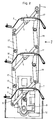
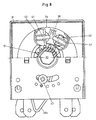
- Fig. 1 and 2 show a Roman blind in frontal view and in sectional view. According to the frontal view, a number of slats 2 are guided on both sides in guide rails 1 in the usual way.
- the two ends of the two-armed lever 5 hold a chain, formed from articulated support members 17, 18, of which the respective upper support member 17 has bearing openings 11 on both sides for connection to the respective lower support member 18, which has a stop 13 for determining the stretched state the chain.
- a drawstring 14 on the left and right of the slats 2 is fastened at its lower free end to a slide support 12 and this slide support 12 pushes the two slides 7, 8 right and left of the slats downwards or upwards.
- a locking lever 9 is attached to the carriage 7, 8 itself, with which the store located in the lower end position can be secured. As far as this or a modification of this store is well known in specialist circles, it does not need to be described further here.
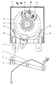
- the reel shaft 29 ends in a hexagonal shaft section 30.
- the band reel 33 which is installed in a housing 31 with a cover 32.
- the tension band 14 (FIGS. 5 to 7) is wound on this band reel 33.
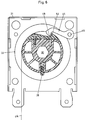
- a rocker 36 (FIG. 4) is rotatably mounted on the hexagonal shaft section 30 and comprises a rocker arm 36a and a control arm 36b, which two parts 36a and 36b are arranged diametrically.
- the rocker arm 36a is provided with an adjustment pocket 36c which protrudes outwards through a slot in the housing and can thus be adjusted from outside the housing but within the cover of the box.
- a locking screw 47 the rocker 36 can be rotated in several discrete positions, e.g.
- a toothed segment 38 (FIG. 8) meshes with a toothed ring 51 held in a rotationally fixed manner on the shaft part 30. By rotating the shaft part 30, the toothed segment 38 is moved to the left or to the right for lowering and pulling up the store and is disengaged from the toothed ring 51 .
- the pivoting device is locked by means of locking bolts 42, 43, which are pressed against the flanks of the toothed segment 38 by springs 41, and the band 14 can be unrolled or rolled up.
- the mode of operation will be explained below in the description of the mode of operation.
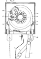
- the tape reel 33 is equipped with a wedge 39 which slides radially into its hub when the tape is wound up (Fig. 5), and when that Band 14 is completely unwound, protrudes from the hub into a locking position (Fig. 6).
- a pawl 45 is rotatably mounted on the housing on a bolt 46. Due to its own weight, this pawl 45 rests on the belt 14 and comes to a stop at a locking surface 52 when the belt 14 is unwound. (Fig. 6)
- Fig. 7 shows the winding phase.
- the pawl 45 is accordingly lifted by the wound band 14 from the pawl stop 48 and half a turn further the wedge 34 is then pressed into the hub of the reel and the store can thus be lifted up.
- the store is stacked in the lintel.
- the cam 53 of the swivel plate 34 is locked in the catch 54 (FIG. 9).
- the fixed cam 37 locks the locking bolt 42 so that the toothed segment 38 remains in position outside of the engagement with the ring gear 51.
- the pawl 45 (FIG. 5) rests on the band 14 wound on the band reel 33 and slides on the band 14 during rotation.
- the further rotation of the reel shaft 29 has the effect that the toothed segment 38 is further rotated counterclockwise by the ring gear 51 and the locking bolt 42 is thereby lifted off the control curve 37.
- the toothed segment 38 is carried along until it is no longer in engagement with the ring gear 51. This causes the spring 41 to be tensioned and press the toothed segment 38 against the ring gear 51.
- the swivel plate 34 is locked and uncoupled by the engagement of the cam 53 in the catch 49, the tape 14 is unrolled by the further winding of the reel 33 and the store lowers with the slats 49 opened by the set angle of the catch 49.
- the band 14 releases the pawl 45, which thereby comes to rest and by which the wedge 44 is released so that it can be pressed outwards by the wedge spring 44a.
- the wedge 44 engages in a groove in the swivel disk 34 and takes it with it. After a rotation of 180 °, the swivel disk 34 is locked by the pawl 45 and the store is in the closed position of the slats.
- the hexagonal shaft 30 and thus the tape reel 33 are rotated clockwise.
- the ring gear 51 takes the toothed segment 38 with it. This makes a counterclockwise rotation and abuts the locking bolt 43. Torque is thus transmitted to the swivel plate 34 via ring gear 51, toothed segment 38 and locking bolt 43. This now turns together with the reel 33 in a clockwise direction.
- the cam 53 is thus pressed out of the detent and the locking bolt 43 slides on the control cam 37.
- the locking bolt 42 thus relieved is pressed down by the spring 41 against the swivel plate 34 and the cam 53 engages in the detent 49 on the adjustment pocket 36c and the locking bolt 42 is released. In the meantime, the locking bolt 43 slides on the cam 37 and is held down.
- the released locking bolt 42 is pushed upwards by the rotating swivel disk 34.
- the toothed segment 38 continues to rotate counterclockwise until it no longer meshes with the ring gear 51. However, it is pressed against the ring gear 51 by its own weight. Because the swivel plate 34 is locked but uncoupled, the further winding of the reel 33 causes the band 14 to be wound up.
- the wedge 44 is pressed inwards by the band 14 and by the groove in the swivel plate 34.
Abstract
Description
Die vorliegende Erfindung betrifft eine Lamellenstore gemäss dem Oberbegriff des unabhängigen Anspruchs 1.The present invention relates to a slat blind according to the preamble of
Unter den Begriff "Lamellenstore" fallen sowohl Rafflamellenstore als auch Ganzmetallstore. Diese dienen der Sicherung der Fenster und der Beschattung von Räumen. Die Lamellen sind seitlich mit Zapfen versehen, die durch vertikale Schlitze in seitlichen Führungsschienen hindurchragen und in eine Kettenlasche eingreifen. Die Kettenlaschen sind an ihren beiden Enden durch Tragglieder miteinander drehbeweglich verbunden, so dass durch Verändern der Stellung der Traggliederpaare zueinander die Kettenlaschen in ihrer Lage verändert werden. Damit kann üblicherweise bewirkt werden, dass die Lamellen in der ganz abgesenkten Lage der Store von der normalsenkrechten Stellung in eine horizontale Stellung geschwenkt werden können. Diese beiden Stellungen werden automatisch durch die Bewegung der Store eingenommen. Beim Absenken bleiben die Lamellen in geschlossener oder vertikaler Stellung und können mittels einer kleinen Gegenbewegung, wie beim Hochziehen der Store in die offene oder horizontale Stellung gebracht werden. Der jeweilige Raum wird damit entweder vollständig beschattet bzw. ganz dunkel oder die Sonnenstrahlung kann nicht in dem gewünschten Mass beschattet werden.The term "slat blind" includes both roman blinds and all-metal blinds. These serve to secure the windows and shade rooms. The slats are laterally provided with pins that protrude through vertical slots in the side guide rails and engage in a link plate. The link plates are rotatably connected to one another at their two ends by support members, so that the position of the link plates can be changed by changing the position of the pairs of support members. This can usually have the effect that the slats can be pivoted from the normal vertical position into a horizontal position in the completely lowered position of the store. These two positions are automatically assumed by the movement of the store. When lowering, the slats remain in the closed or vertical position and can be brought into the open or horizontal position by means of a small counter-movement, as when pulling up the store. The respective room is either completely shaded or completely dark or the solar radiation cannot be shaded to the desired extent.
Gemäss der DE-C-26 42 655 wurde dementsprechend vorgeschlagen, eine Begrenzung der bei der beim Absenken einsetzenden Wendebewegung vorzusehen, um die Lamellen in einer gegebenen Zwischenstellung abzusenken. Bei dieser bekannten Anordnung braucht es ausser dem beidseits wirkenden Auf- und Abwickelband zum Absenken und zum Hochziehen noch ein weiteres Betätigungselement für die Steuerung der Stellung der Lamellen.According to DE-C-26 42 655, it was accordingly proposed to provide a limitation of the turning movement that occurs when lowering in order to lower the slats in a given intermediate position. In this known arrangement, in addition to the winding and unwinding belt acting on both sides, for lowering and for pulling up, a further actuating element for controlling the position of the slats is required.
Auch in der DE-A-37 22 604 ist eine Wendevorrichtung für Rafflamellenstore beschrieben. Bei dieser Anordnung ist erwünscht, dass die Lamellen in der abgesenkten Lage nicht zwangsläufig in die Schliessstellung gebracht werden, sondern in einer halboffenen Stellung bleiben. Auch hier sind spezielle Bedienungsschnüre für das Wenden bzw. zum Voreinstellen der Lamellenstellung vorgesehen.DE-A-37 22 604 also describes a turning device for Roman blinds. With this arrangement, it is desirable that the slats in the lowered position are not necessarily brought into the closed position, but remain in a semi-open position. Special operating cords are also provided here for turning or for pre-setting the slat position.
In der CH-A- 650 311 ist eine Rafflamellenstore beschrieben, bei der die Lamellen drei Stellungen, nämlich eine offene, eine teilweise offene und eine geschlossene Stellung einnehmen können. Es ist vorgesehen, dass die halboffene Stellung beim Absenken nur solange beibehalten werden kann, als die Store nicht ganz abgesenkt ist. Bei vollständig abgesenkter Store nehmen die Lamellen selbsttätig die geschlossene Stellung ein.In CH-A-650 311 a Roman blind is described, in which the slats can assume three positions, namely an open, a partially open and a closed position. It is envisaged that the semi-open position when lowering can only be maintained as long as the store is not fully lowered. When the store is completely lowered, the slats automatically assume the closed position.
Demgemäss besteht die Aufgabe der Erfindung darin, eine Rafflamellenstore zu schaffen, bei der eine zusätzliche werkseitig eingestellte Lage der Lamellen nach Bedarf der Beschattung ohne zusätzliche Einstellseile oder Schnüre oder dgl. möglich ist und bei der diese zusätzliche Lage über die gesamte Hublänge, also auch in ganz abgesenkter Lage beibehalten wird.Accordingly, the object of the invention is to provide a Roman blind, in which an additional factory-set position of the slats is possible according to the need for shading without additional adjustment ropes or cords or the like, and in which this additional position over the entire stroke length, also in completely lowered position is maintained.
Erfindungsgemäss wird dies durch die Merkmale im kennzeichnenden Teil des unabhängigen Patentanspruchs 1 erreicht.According to the invention this is achieved by the features in the characterizing part of
Nachfolgend wird ein Ausführungsbeispiel der Erfindung an Hand der Zeichnung erläutert. Es zeigen:
- Fig.1
- eine Frontansicht der Haltestäbe für Lamellen mit den Führungen in den Schienen von rechts in Fig.2 gemäss dem Pfeil I betrachtet,
- Fig.2
- eine Schnittansicht gemäss der Schnittlinie II-II in Fig 1 mit Lamellen in offener Stellung auf den Haltestäben,
- Fig.3
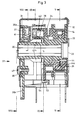
- eine Schnittansicht einer Steuerung für die Betätigungsvorrichtung in Form einer Wippe gemäss der Schnittlinie III
- Fig.4
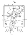
- eine Frontansicht der Wippensteuerung gemäss dem Pfeil IV in Fig. 3 ohne das Gehäuse,
- Fig.5
- eine Schnittansicht der Wippensteuerung gemäss der Schnittlinie V-V in Fig.3,
- Fig.6
- eine ähnliche Schnittansicht wie in Fig. 5 jedoch mit abgehaspeltem Band,
- Fig.7
- eine weitere Schnittansicht wie in Fig. 6 kurz nach dem Beginn des Hochhebens der Store,
- Fig.8
- einen Ausschnitt aus einer Schnittansicht gemäss der Schnittlinie VIII-VIII in Fig. 3,
- Fig.9
- eine Schnittansicht gemäss der Schnittlinie IX-IX in Fig. 3 mit den Lamellen in Horizontalstellung,
- Fig.10
- dieselbe Schnittansicht wie in Fig.9 mit den Lamellen in Arbeitsstellung, d.h.in offener Stellung, und
- Fig.11
- dieselbe Schnittansicht wie in Fig. 9 mit den Lamellen in Schliessstellung.
- Fig. 1
- a front view of the holding rods for slats with the guides in the rails viewed from the right in Figure 2 according to arrow I,
- Fig. 2
- 2 shows a sectional view according to section line II-II in FIG. 1 with lamellae in the open position on the holding rods,
- Fig. 3
- a sectional view of a control for the actuating device in the form of a rocker according to section line III
- Fig. 4
- 3 shows a front view of the rocker control according to arrow IV in FIG. 3 without the housing,
- Fig. 5
- 3 shows a sectional view of the rocker control according to the section line VV in FIG. 3,
- Fig. 6
- 5 shows a similar sectional view as in FIG. 5, but with the tape unwound,
- Fig. 7
- 6 shows a further sectional view as in FIG. 6 shortly after the start of lifting the store,
- Fig. 8
- 3 shows a section of a sectional view along the section line VIII-VIII in FIG. 3,
- Fig. 9
- 3 shows a sectional view along the section line IX-IX in FIG. 3 with the slats in the horizontal position,
- Fig. 10
- the same sectional view as in Fig. 9 with the slats in the working position, therefore open position, and
- Fig. 11
- the same sectional view as in Fig. 9 with the slats in the closed position.
Fig, 1 und 2 zeigen eine Rafflamellenstore in Frontalansicht und in Schnittansicht. Gemäss der Frontalansicht ist eine Anzahl Lamellen 2 beidseits in Führungsschienen 1 in üblicher Weise geführt. Der an den Lamellen befestigten Lamellenhalter 4, die beidseits jeder Lamelle 2 vorhanden ist, trägt je eine Achse 6, die in bekannter Weise in die seitliche Führungsschiene 1 eingreift und dort mittig an einem zweiarmigen Hebel 5 drehbar gelagert ist. Die beiden Enden des zweiarmigen Hebels 5 haltern eine Kette, gebildet aus gelenkig verbundenen Traggliedern 17,18, von denen das jeweils obere Tragglied 17 beidseits Lageröffnungen 11 zur Verbindung mit dem jeweils unteren Tragglied 18, das mit einem Anschlag 13 für die Festlegung des gestreckten Zustandes der Kette. Je ein Zugband 14 links und rechts der Lamellen 2 ist an seinem unteren freien Ende an einem Schlittenträger 12 befestigt und dieser Schlittenträger 12 schiebt die beiden Schlitten 7,8 rechts und links der Lamellen nach unten oder nach oben. An den Schlitten 7,8 selbst ist ein Verriegelungshebel 9 angebracht, mit dem die in der unteren Endlage befindlichen Store gesichert werden kann. Soweit ist diese oder eine Modifikation dieser Store in Fachkreisen gut bekannt und braucht an dieser Stelle nicht weiter beschrieben zu werden.Fig. 1 and 2 show a Roman blind in frontal view and in sectional view. According to the frontal view, a number of
Die Erfindungsidee, die darin besteht, die Lamellen in vorgegebener Schrägstellung abzusenken und damit eine windgesicherte Arbeitsstellung zu schaffen, die im Raum insbesondere bei automatischem motorischem Antrieb aber auch bei Handbetätigung beim Absenken eine gewünschte Helligkeit gewährleistet, wird nun nachfolgend mit Bezug auf Fig.3 und 4 erläutert. Steuerelemente für die Festlegung der beiden Endstellungen, vertikal bzw. geschlossen und horizontal oder offen, sowie eine Mittelstellung zur lichtgerechten Beschattung sind mit den beiden Bandhaspeln links und rechts verbunden. Der Kürzung der Beschreibung wegen wird nachfolgend nur der rechts befindliche Bandhaspel beschrieben, der links befindliche Bandhaspel ist symmetrisch aufgebaut.The idea of the invention, which consists in lowering the slats in a predetermined inclined position and thus creating a wind-protected working position, which ensures a desired brightness in the room, in particular with automatic motor drive but also with manual operation when lowering, is now described below with reference to FIGS 4 explained. Controls for setting the two end positions, vertical or closed and horizontally or openly, as well as a central position for light-appropriate shading, are connected to the two reels on the left and right. To shorten the description, only the ribbon reel on the right is described below; the ribbon reel on the left is constructed symmetrically.
Die Haspelwelle 29 endet in einem Sechskantwellenabschnitt 30. Auf diesem Wellenteil 30 befindet sich der Bandhaspel 33 der in ein Gehäuse 31 mit Deckel 32 eingebaut ist, Auf diesem Bandhaspel 33 ist das Zugband 14 (Fig. 5 bis 7) aufgewickelt. Auf dem Sechskantwellenabschnitt 30 ist eine Wippe 36 (Fig. 4) drehbar gelagert, die einen Wippenarm 36a und einen Steuerarm 36b umfasst, welche beiden Teile 36a und 36b diametral angeordnet sind. Der Wippenarm 36a ist mit einer Einstellasche 36c versehen, die durch einen Schlitz im Gehäuse nach aussen ragt und damit von ausserhalb des Gehäuses, aber innerhalb der Abdeckung des Kastens, verstellt werden kann. Mittels einer Feststellschraube 47 kann die Wippe 36 in mehreren diskreten Drehlagen, z.B. für 30°, 37°, 45°, 53° und 60° Schrägstellung der Lamellen 2 festgestellt werden. Der gegenüberliegende Steuerteil 36b wirkt mit einer feststehenden Steuerkurve 37 zusammen. Die Form und die Lage der Steuerkurve 37 sind in Fig. 4 ersichtlich. Ein Zahnsegment 38 (Fig. 8) kämmt mit einem drehfest auf dem Wellenteil 30 gehalterten Zahnkranz 51. Durch Verdrehen des Wellenteils 30 wird für Herablassen und Aufziehen der Store das Zahnsegment 38 nach links oder nach rechts bewegt und aus dem Eingriff mit dem Zahnkranz 51 genommen. Durch Verriegelungsbolzen 42,43, die mit Federn 41 gegen die Flanken des Zahnsegmentes 38 gedrückt sind, wird die Schwenkvorrichtung arretiert und das Band 14 kann abgerollt oder aufgerollt werden. Die Wirkungsweise wird weiter unten bei der Beschreibung der Arbeitsweise erläutert werden.The
Der Bandhaspel 33 ist mit einem Keil 39 ausgerüstet, der sich radial in deren Nabe einschiebt, wenn das Band aufgewickelt wird (Fig. 5), und wenn das Band 14 vollkommen abgewickelt ist, aus der Nabe heraus in eine Verriegelungsstellung hinausragt (Fig. 6). Eine Klinke 45 ist gehäusefest an einem Bolzen 46 drehbar gelagert. Durch ihr Eigengewicht liegt diese Klinke 45 auf dem Band 14 auf und kommt bei abgewickelten Band 14 an einer Rastfläche 52 zum Anschlag. (Fig. 6)The
Fig. 7 zeigt die Aufwickelphase. Die Klinke 45 wird demgemäss durch das aufgewickelte Band 14 vom Klinkenanschlag 48 abgehoben und eine halbe Umdrehung weiter wird dann auch der Keil 34 in die Nabe des Haspels hineingedrückt und damit kann die Store hochgehoben werden.Fig. 7 shows the winding phase. The
Nachfolgend wird die Funktionsweise der Vorrichtung zum Raffen, Absenken in partieller Drehlage Lamellen an Hand der Fig. 8 bis 11 unter Zuhilfenahme der vorbeschriebenen Fig. 1 bis 7 beschrieben.The mode of operation of the device for gathering, lowering in the partial rotational position of the slats is described with the aid of FIGS. 8 to 11 with the aid of the previously described FIGS. 1 to 7.
Die Store ist gestapelt im Fenstersturz. Der Nocken 53 der Schwenkscheibe 34 ist in der Rast 54 eingerastet (Fig.9). In dieser Position verriegelt die feste Steuerkurve 37 den Verriegelungsbolzen 42, so dass das Zahnsegment 38 in Position ausserhalb des Eingriffes mit dem Zahnkranz 51 bleibt. Die Klinke 45 (Fig.5) liegt durch ihr Eigengewicht auf dem auf dem Bandhaspel 33 aufgewickelten Band 14 auf und gleitet während des Drehens auf dem Band 14.The store is stacked in the lintel. The
Durch Drehen der Haspelwelle 29 und damit der Sechskantwelle 30 im Gegenuhrzeigersinn (Fig. 9) wird ein Drehmoment auf den Zahnkranz 51 übertragen. Der Zahnkranz drückt das Zahnsegment 38 gegen den Verriegelungsbolzen 42 und damit wird die Schwenkscheibe 34 ebenfalls in Gegenuhrzeigerrichtung gedrückt. Der Verriegelungsbolzen 42 wird nach links gedrückt und gleitet auf der Steuerkurve 37 (Fig.4). Bei Erreichen der " Arbeitsstellung", d.h. die Stellung, in der die Absenkung des Stores beginnt, rastet der Nocken 53 in die Arretierung 49 ein und der Verriegelungsbolzen 43 wird freigegeben (Fig.10).By turning the
Das Weiterdrehen der Haspelwelle 29 bewirkt, dass das Zahnsegment 38 durch den Zahnkranz 51 im Gegenuhrzeigersinn weiter gedreht wird und dadurch der Verriegelungsbolzen 42 von der Steuerkurve 37 abgehoben wird. Das Zahnsegment 38 wird solange mitgenommen, bis es nicht mehr im Eingriff mit dem Zahnkranz 51 steht. Dies bewirkt, dass die Feder 41 gespannt wird und das Zahnsegment 38 gegen den Zahnkranz 51 drückt.The further rotation of the
Weil die Schwenkscheibe 34 durch den Eingriff des Nockens 53 in die Rast 49 arretiert und entkuppelt ist, wird durch das Weiterdrehen des Bandhaspels 33 das Band 14 abgerollt und die Store senkt sich mit um den eingstellten Winkel der Rast 49 geöffneten Lamellen ab. Kurz vor Erreichen der Schliessstellung gibt das Band 14 die Klinke 45 frei, die dadurch aufzuliegen kommt und wodurch der Keil 44 freigegeben wird, so dass er durch die Keilfeder 44a nach aussen gedrückt werden kann. Durch Weiterdrehen der Wellen 29,30 greift dann der Keil 44 in eine Nut in der Schwenkscheibe 34 ein und nimmt diese mit. Nach einer Drehung von 180° wird die Schwenkscheibe 34 durch die Klinke 45 arretiert und die Store befindet sich in der Schliessstellung der Lamellen.Because the
Die Sechskantwelle 30 und damit der Bandhaspel 33 werden im Uhrzeigersinn gedreht. Der Zahnkranz 51 nimmt das Zahnsegment 38 mit. Dieses führt eine Drehung im Gegenuhrzeigersinn aus und stösst an dem Verriegelungsbolzen 43 an. Damit wird ein Drehmoment über Zahnkranz 51, Zahnsegment 38 und Verriegelungsbolzen 43 auf die Schwenkscheibe 34 übertragen. Diese dreht sich nun zusammen mit dem Bandhaspel 33 im Uhrzeigersinn. Damit wird der Nocken 53 aus der Arretierung gedrückt und der Verriegelungsbolzen 43 gleitet auf der Steuerkurve 37. Der damit entlastete Verriegelungsbolzen 42 wird durch die Feder 41 nach unten gegen die Schwenkscheibe 34 gedrückt und der Nocken 53 rastet in der Rast 49 auf der Einstellasche 36c ein und der Verriegelungsbolzen 42 wird freigegeben. Währenddessen gleitet der Verriegelungsbolzen 43 auf der Steuerkurve 37 und wird unten gehalten. Der freigegebene Verriegelungsbolzen 42 wird durch die sich drehende Schwenkscheibe 34 nach oben geschoben. Das Zahnsegment 38 dreht sich weiter im Gegenuhrzeigersinn bis es mit dem Zahnkranz 51 nicht mehr kämmt. Jedoch wird es durch sein Eigengewicht gegen den Zahnkranz 51 gedrückt. Weil die Schwenkscheibe 34 arretiert aber entkuppelt ist, bewirkt das Weiterdrehen des Bandhaspels 33, dass das Band 14 aufgewickelt wird. Der Keil 44 wird durch das Band 14 sowie durch die Nut in der Schwenkscheibe 34 nach innen gedrückt.The
Wenn die Store mit den Lamellen senkrecht in geschlossener Stellung ganz nach oben gezogen ist und kein Drehmoment mehr auf das Band 14 wirkt, so wirkt stattdessen das vom Gewicht des Behanges herrührende Drehmoment auf den Bandhaspel 33. Dieser dreht sich dadurch im Gegenuhrzeigersinn und der Zahnkranz 51 nimmt das Zahnsegment 38 mit, bis dieses an dem Verriegelungsbolzen 43 anstösst. Die Feder 41 drückt diesen Verriegelungsbolzen 43 nach unten und die Store ist oben mit aufeinander aufliegenden Lamellen arretiert.If the store with the slats is pulled vertically upwards in the closed position and no more torque acts on the
Claims (5)
- Gatherable slatted blind having a device which is arranged on a winder shaft (29) and is intended for gathering or lowering the blind, and also having means for rotating the slats (2) between a first position, in which the slats (2) are closed and butt at least approximately vertically against one another, and a second position, in which the slats (2) are located horizontally and parallel to one another, characterized in that provision is made of a toothed rim (51) which is fastened in a rotationally fixed manner on the winder shaft (29) and meshes with a toothed segment (38) for actuating locking bolts (42, 43), which are pressed against the tooth flanks of said tooth segment by means of a spring (41), for the purpose of limiting the rotary angle, in that the toothed segment (38) is fastened rotatably on a pivot disk (34), and the locking bolts (42, 43) serve as a stop for a rocker (36) which is designed as a centrally rotationally mounted two-armed lever with a rocker arm (36a) and a control arm (36b), and in that the pivot disk (34) has a protrusion (53) which serves for engaging in the latching means (49) on the rocker arm (36a) and in housing-mounted, resilient latching means (54, 55) for the two positions, open and closed.
- Blind according to Patent Claim 1, characterized in that the rocker arm (36a) is provided with a setting tongue (36c) and a securing screw (47) in order to secure the rocker arm (36a) in the envisaged position between the open and closed positions of the slats, and thus to secure the position of the latching means (49).
- Blind according to Patent Claim 2, characterized in that the rocker arm (36a) can be adjusted with respect to the latching means (54, 55) by an angle of between 30° and 90°, preferably an angle of between 40° and 65°.
- Blind according to one of Patent Claims 1 to 3, characterized in that provided on the winder shaft (29, 30) is a winder (33) for the cord (14) for lowering or drawing up the blind, and in that a detent (45) is kept, by way of the cord (14), out of engagement with a detent stop (48) provided on the circumference of the cord winder (33), and it is only when the cord (14) has been unwound to the full extent that said detent is released for engagement in the detent stop (48), in order to fix the bottom end position.
- Blind according to one of Patent Claims 1 to 4, characterized in that the cord winder (33) is mounted by means of a hexagonal shaft (30) which is connected rigidly to the winder shaft (29) and has an extended hub, on which the toothed rim (51) is fastened for driving the toothed segment (38).
Applications Claiming Priority (2)
| Application Number | Priority Date | Filing Date | Title |
|---|---|---|---|
| CH825/92A CH685402A5 (en) | 1992-03-16 | 1992-03-16 | Venetian blind. |
| CH825/92 | 1992-03-16 |
Publications (3)
| Publication Number | Publication Date |
|---|---|
| EP0561266A2 EP0561266A2 (en) | 1993-09-22 |
| EP0561266A3 EP0561266A3 (en) | 1994-01-05 |
| EP0561266B1 true EP0561266B1 (en) | 1997-11-05 |
Family
ID=4196079
Family Applications (1)
| Application Number | Title | Priority Date | Filing Date |
|---|---|---|---|
| EP93103862A Expired - Lifetime EP0561266B1 (en) | 1992-03-16 | 1993-03-10 | Lamellar blind |
Country Status (4)
| Country | Link |
|---|---|
| EP (1) | EP0561266B1 (en) |
| AT (1) | ATE159998T1 (en) |
| CH (1) | CH685402A5 (en) |
| DE (1) | DE59307618D1 (en) |
Families Citing this family (2)
| Publication number | Priority date | Publication date | Assignee | Title |
|---|---|---|---|---|
| CH696498A5 (en) * | 2003-07-11 | 2007-07-13 | Griesser Holding Ag | A venetian blind. |
| JP4561268B2 (en) * | 2004-09-16 | 2010-10-13 | オイレスEco株式会社 | Blind device |
Family Cites Families (7)
| Publication number | Priority date | Publication date | Assignee | Title |
|---|---|---|---|---|
| CH503885A (en) * | 1969-08-25 | 1971-02-28 | Griesser Ag | Venetian blinds |
| CH523418A (en) * | 1970-05-12 | 1972-05-31 | Fiblex S A | Orientation mechanism for slatted blinds |
| CH608563A5 (en) * | 1976-04-30 | 1979-01-15 | Schenker Emil Storen Und Masch | |
| CH650311A5 (en) * | 1981-05-19 | 1985-07-15 | Baumann Rolladen | REEL SLAT STORE. |
| SE8203812L (en) * | 1982-06-18 | 1983-12-19 | Perma System Ab | STOCK BOCK FOR FACING PERSONALS |
| DE3511246A1 (en) * | 1985-03-28 | 1986-10-02 | Theophil Dipl.-Ing. 7300 Esslingen Pfeffer | Screening or protecting device for wall openings or the like, in particular a roller shutter or a blind |
| DE3610028C2 (en) * | 1986-03-25 | 1996-07-25 | Rau Metall Gmbh & Co | Turning device for Roman blinds |
-
1992
- 1992-03-16 CH CH825/92A patent/CH685402A5/en not_active IP Right Cessation
-
1993
- 1993-03-10 AT AT93103862T patent/ATE159998T1/en active
- 1993-03-10 EP EP93103862A patent/EP0561266B1/en not_active Expired - Lifetime
- 1993-03-10 DE DE59307618T patent/DE59307618D1/en not_active Expired - Fee Related
Also Published As
| Publication number | Publication date |
|---|---|
| CH685402A5 (en) | 1995-06-30 |
| EP0561266A2 (en) | 1993-09-22 |
| EP0561266A3 (en) | 1994-01-05 |
| ATE159998T1 (en) | 1997-11-15 |
| DE59307618D1 (en) | 1997-12-11 |
Similar Documents
| Publication | Publication Date | Title |
|---|---|---|
| DE69826566T2 (en) | Turning mechanism for a blind | |
| DE7529767U (en) | BAR-ACTUATED BLIND | |
| DE3037701A1 (en) | SHUTTERS, SHUTTERS OR THE LIKE | |
| DE10316836B4 (en) | Electrically operated blind | |
| DE2805836C2 (en) | Venetian blinds | |
| DE2312661A1 (en) | FOLDING BLIND | |
| EP0050677B1 (en) | Venetian blind | |
| AT394880B (en) | REEL SLAT STORE | |
| DE3037759A1 (en) | REEL SLAT STORE | |
| DE3625365A1 (en) | Turning device for a slatted blind which can be gathered up and has three slat positions | |
| EP0561266B1 (en) | Lamellar blind | |
| CH650311A5 (en) | REEL SLAT STORE. | |
| DE3731374C2 (en) | ||
| EP1072753A2 (en) | Venetian blind | |
| DE2452549C3 (en) | Venetian blind | |
| EP0383067B1 (en) | Roller shutter for wall or roof openings, especially those with a swinging roof window | |
| AT502509B1 (en) | LOUVRE | |
| DE1683177A1 (en) | Cord drive device for blinds with slats | |
| EP1213437A2 (en) | Lamellar blind with tilting mechanism | |
| EP1213439A2 (en) | Covering device | |
| DE4100609A1 (en) | Roller blind drive mechanism - has bottom-mounted single electric motor for two=way control | |
| EP0322355B1 (en) | Venetian blind | |
| DE3037733A1 (en) | REEL SLAT STORE | |
| DE2201056B1 (en) | Turning device for a slatted blind that can be gathered | |
| DE3037703A1 (en) | Venetian blinds with guide elements arranged at the ends of the slats |
Legal Events
| Date | Code | Title | Description |
|---|---|---|---|
| PUAI | Public reference made under article 153(3) epc to a published international application that has entered the european phase |
Free format text: ORIGINAL CODE: 0009012 |
|
| AK | Designated contracting states |
Kind code of ref document: A2 Designated state(s): AT BE CH DE DK ES FR GB GR IT LI LU NL SE |
|
| PUAL | Search report despatched |
Free format text: ORIGINAL CODE: 0009013 |
|
| AK | Designated contracting states |
Kind code of ref document: A3 Designated state(s): AT BE CH DE DK ES FR GB GR IT LI LU NL SE |
|
| 17P | Request for examination filed |
Effective date: 19931224 |
|
| 17Q | First examination report despatched |
Effective date: 19951102 |
|
| GRAG | Despatch of communication of intention to grant |
Free format text: ORIGINAL CODE: EPIDOS AGRA |
|
| GRAH | Despatch of communication of intention to grant a patent |
Free format text: ORIGINAL CODE: EPIDOS IGRA |
|
| GRAH | Despatch of communication of intention to grant a patent |
Free format text: ORIGINAL CODE: EPIDOS IGRA |
|
| GRAA | (expected) grant |
Free format text: ORIGINAL CODE: 0009210 |
|
| AK | Designated contracting states |
Kind code of ref document: B1 Designated state(s): AT BE CH DE DK ES FR GB GR IT LI LU NL SE |
|
| PG25 | Lapsed in a contracting state [announced via postgrant information from national office to epo] |
Ref country code: NL Free format text: LAPSE BECAUSE OF FAILURE TO SUBMIT A TRANSLATION OF THE DESCRIPTION OR TO PAY THE FEE WITHIN THE PRESCRIBED TIME-LIMIT Effective date: 19971105 Ref country code: GR Free format text: LAPSE BECAUSE OF FAILURE TO SUBMIT A TRANSLATION OF THE DESCRIPTION OR TO PAY THE FEE WITHIN THE PRESCRIBED TIME-LIMIT Effective date: 19971105 Ref country code: GB Free format text: LAPSE BECAUSE OF FAILURE TO SUBMIT A TRANSLATION OF THE DESCRIPTION OR TO PAY THE FEE WITHIN THE PRESCRIBED TIME-LIMIT Effective date: 19971105 Ref country code: ES Free format text: THE PATENT HAS BEEN ANNULLED BY A DECISION OF A NATIONAL AUTHORITY Effective date: 19971105 Ref country code: DK Free format text: LAPSE BECAUSE OF NON-PAYMENT OF DUE FEES Effective date: 19971105 |
|
| REF | Corresponds to: |
Ref document number: 159998 Country of ref document: AT Date of ref document: 19971115 Kind code of ref document: T |
|
| REG | Reference to a national code |
Ref country code: CH Ref legal event code: NV Representative=s name: NOVATOR AG Ref country code: CH Ref legal event code: EP |
|
| REF | Corresponds to: |
Ref document number: 59307618 Country of ref document: DE Date of ref document: 19971211 |
|
| ET | Fr: translation filed | ||
| ITF | It: translation for a ep patent filed |
Owner name: UFFICIO BREVETTI RICCARDI & C. |
|
| PG25 | Lapsed in a contracting state [announced via postgrant information from national office to epo] |
Ref country code: SE Free format text: LAPSE BECAUSE OF FAILURE TO SUBMIT A TRANSLATION OF THE DESCRIPTION OR TO PAY THE FEE WITHIN THE PRESCRIBED TIME-LIMIT Effective date: 19980205 |
|
| PG25 | Lapsed in a contracting state [announced via postgrant information from national office to epo] |
Ref country code: LU Free format text: LAPSE BECAUSE OF NON-PAYMENT OF DUE FEES Effective date: 19980310 |
|
| NLV1 | Nl: lapsed or annulled due to failure to fulfill the requirements of art. 29p and 29m of the patents act | ||
| GBV | Gb: ep patent (uk) treated as always having been void in accordance with gb section 77(7)/1977 [no translation filed] |
Effective date: 19971105 |
|
| PLBE | No opposition filed within time limit |
Free format text: ORIGINAL CODE: 0009261 |
|
| STAA | Information on the status of an ep patent application or granted ep patent |
Free format text: STATUS: NO OPPOSITION FILED WITHIN TIME LIMIT |
|
| 26N | No opposition filed | ||
| PGFP | Annual fee paid to national office [announced via postgrant information from national office to epo] |
Ref country code: CH Payment date: 20000320 Year of fee payment: 8 |
|
| PGFP | Annual fee paid to national office [announced via postgrant information from national office to epo] |
Ref country code: BE Payment date: 20000329 Year of fee payment: 8 |
|
| PGFP | Annual fee paid to national office [announced via postgrant information from national office to epo] |
Ref country code: FR Payment date: 20000330 Year of fee payment: 8 Ref country code: AT Payment date: 20000330 Year of fee payment: 8 |
|
| PGFP | Annual fee paid to national office [announced via postgrant information from national office to epo] |
Ref country code: DE Payment date: 20000517 Year of fee payment: 8 |
|
| PG25 | Lapsed in a contracting state [announced via postgrant information from national office to epo] |
Ref country code: AT Free format text: LAPSE BECAUSE OF NON-PAYMENT OF DUE FEES Effective date: 20010310 |
|
| PG25 | Lapsed in a contracting state [announced via postgrant information from national office to epo] |
Ref country code: LI Free format text: LAPSE BECAUSE OF NON-PAYMENT OF DUE FEES Effective date: 20010331 Ref country code: CH Free format text: LAPSE BECAUSE OF NON-PAYMENT OF DUE FEES Effective date: 20010331 Ref country code: BE Free format text: LAPSE BECAUSE OF NON-PAYMENT OF DUE FEES Effective date: 20010331 |
|
| BERE | Be: lapsed |
Owner name: E. KINDT A.G. VORMALS HANS KIEFER A.G. Effective date: 20010331 |
|
| REG | Reference to a national code |
Ref country code: CH Ref legal event code: PL |
|
| PG25 | Lapsed in a contracting state [announced via postgrant information from national office to epo] |
Ref country code: FR Free format text: LAPSE BECAUSE OF NON-PAYMENT OF DUE FEES Effective date: 20011130 |
|
| REG | Reference to a national code |
Ref country code: FR Ref legal event code: ST |
|
| PG25 | Lapsed in a contracting state [announced via postgrant information from national office to epo] |
Ref country code: DE Free format text: LAPSE BECAUSE OF NON-PAYMENT OF DUE FEES Effective date: 20020101 |
|
| PG25 | Lapsed in a contracting state [announced via postgrant information from national office to epo] |
Ref country code: IT Free format text: LAPSE BECAUSE OF NON-PAYMENT OF DUE FEES;WARNING: LAPSES OF ITALIAN PATENTS WITH EFFECTIVE DATE BEFORE 2007 MAY HAVE OCCURRED AT ANY TIME BEFORE 2007. THE CORRECT EFFECTIVE DATE MAY BE DIFFERENT FROM THE ONE RECORDED. Effective date: 20050310 |