EP0560065A1 - Dispositif pour tailler des roues dentées cylindriques ou coniques - Google Patents
Dispositif pour tailler des roues dentées cylindriques ou coniques Download PDFInfo
- Publication number
- EP0560065A1 EP0560065A1 EP93101984A EP93101984A EP0560065A1 EP 0560065 A1 EP0560065 A1 EP 0560065A1 EP 93101984 A EP93101984 A EP 93101984A EP 93101984 A EP93101984 A EP 93101984A EP 0560065 A1 EP0560065 A1 EP 0560065A1
- Authority
- EP
- European Patent Office
- Prior art keywords
- workpiece table
- axis
- movement
- gear
- tool
- Prior art date
- Legal status (The legal status is an assumption and is not a legal conclusion. Google has not performed a legal analysis and makes no representation as to the accuracy of the status listed.)
- Withdrawn
Links
Images


Classifications
-
- B—PERFORMING OPERATIONS; TRANSPORTING
- B23—MACHINE TOOLS; METAL-WORKING NOT OTHERWISE PROVIDED FOR
- B23F—MAKING GEARS OR TOOTHED RACKS
- B23F23/00—Accessories or equipment combined with or arranged in, or specially designed to form part of, gear-cutting machines
- B23F23/12—Other devices, e.g. tool holders; Checking devices for controlling workpieces in machines for manufacturing gear teeth
- B23F23/1293—Workpiece heads
-
- B—PERFORMING OPERATIONS; TRANSPORTING
- B23—MACHINE TOOLS; METAL-WORKING NOT OTHERWISE PROVIDED FOR
- B23F—MAKING GEARS OR TOOTHED RACKS
- B23F5/00—Making straight gear teeth involving moving a tool relatively to a workpiece with a rolling-off or an enveloping motion with respect to the gear teeth to be made
- B23F5/02—Making straight gear teeth involving moving a tool relatively to a workpiece with a rolling-off or an enveloping motion with respect to the gear teeth to be made by grinding
- B23F5/08—Making straight gear teeth involving moving a tool relatively to a workpiece with a rolling-off or an enveloping motion with respect to the gear teeth to be made by grinding the tool being a grinding disc having the same profile as the tooth or teeth of a rack
Definitions
- the invention relates to a device for the optional machining of spur or bevel gears with a workpiece table carrying the gear, which carries out a translational reciprocating movement in addition to a rotary movement and with a carriage carrying the tool, which carries out lifting movements along the tooth flanks of the gear.
- Such machines are known in the form of tooth flank grinding machines. You preferably work in the partial hobbing process with a double cone pulley.
- the grinding slide In the production of spur gear wheels, the grinding slide carries out a stroke movement parallel to the gear axis, whereas in the production of bevel gears, either the lifting plane of the grinding slide is inclined according to the cone angle or a radial movement is superimposed on the grinding slide during the stroke movement, which is carried out by a template or CNC control is generated.
- the tool carries out a stroke movement obliquely to the gearwheel axis, while the gearwheel axis is aligned with the axis of the rotary table carrying it.
- the object of the present invention is to provide a processing machine which is on the one hand optimally suitable for machining spur gearwheels, but on the other hand allows simple, inexpensive measures to produce conical gearwheels much more precisely than in the previously known combined machines is possible.
- geometrically exact bevel gear teeth should also be realizable.
- the workpiece table has an angle-adjustable receptacle for the gear, such that the gear axis can be pivoted out of alignment with the workpiece table axis by a desired cone angle and can be locked in this pivoted-out position.
- the invention is based on the knowledge that the gear wheel axis of rotation, which is inclined with respect to the table axis, results in a toothing with basic circles that constantly change over the tooth width, as is the case with bevel gearings, and that the relative movement between the tool and the gear wheel takes place in this way, that it no longer corresponds to a rolling cylinder, but to the desired generating rolling cone.
- Another advantage of the invention is that the previously required templates or the numerical path control for the oblique movement of the tool slide are eliminated. In addition, this opens up the possibility of working with higher lifting speeds than before.
- the receptacle is provided with a mandrel crossing the gear wheel, which is clamped at both ends.
- the one clamping point is adjustable approximately perpendicular to the axis of the workpiece table, for example in that the counter-holder arranged above the workpiece table can be moved and clamped along a horizontal guide.
- the mandrel itself is advantageously centered between its two clamping points by two balls, one of which is pressed resiliently, so that the lowering of its upper clamping point relative to the counterholder which occurs when the mandrel is inclined is compensated for.
- the slide carrying the tool can, in addition to its lifting movement, a reciprocating pivoting movement corresponding to the rolling movement about a plane wheel axis that perpendicularly intersects the workpiece table axis perform the acting swivel axis.
- This pivoting movement is expediently implemented in such a way that the tool slide is slidably mounted on a carrier which in turn is pivotably mounted on the stand or on the machine bed.
- the tool slide Due to the back and forth swiveling movement of the tool slide, which corresponds to the rotational and translational movement of the gear, the tool is moved exactly so that it represents the virtual generation face wheel, as prescribed in the toothing theory of bevel gears.
- the gear 1 to be machined - in the present case a spur gear - is firmly connected in a manner known per se to a holding mandrel 2 which in turn is clamped between tips 3 and 4 at its two ends.
- the upper tip 3 is mounted in a counter holder 5, which in turn is connected to a carriage 7 via a column 6.
- This carriage 7 carries out the translatory part of the rolling movement to be generated, here a movement perpendicular to the plane of the page. It carries on its upper side a turntable 8, which generates the rotary part of the rolling movement and which has the aforementioned tip 4 in its center and also radially distances one or more drivers 9.
- These drivers 9 are in play-free engagement with grooves 10a with one the drive plate 10 connected to the mandrel 2. In this way, a rolling movement is generated on the rotary table 8 and transmitted to the gear 1.
- the gear wheel is machined by a grinding wheel 11, which is mounted in a lifting carriage 12, which carries out a reciprocating, vertical lifting movement.
- This machine can also machine bevel gears with a small bevel angle.
- the lifting plane of the slide 12 is pivoted in accordance with the desired cone angle in the exemplary embodiment, ie within the leaf plane.
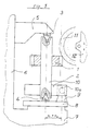
- FIGS. 2 and 3 The design according to the invention, in which these shortcomings are eliminated, is shown in FIGS. 2 and 3. Corresponding parts are provided with the same reference numerals.
- the mandrel 2 with its drive plate 10 can be pivoted out of its aligned position with the axis of rotation of the workpiece table 8, so that the cone angle ⁇ can be set between the axis of the gear wheel 1 and the axis of the rotary table 8.
- the plane of movement of the lifting carriage 12 remains vertical, that is, in a plane parallel to the axis of the rotary table 8.
- the angle of the mandrel 2 is adjusted by dividing the counter-holder 5 into a base body 5a mounted on the column 6 on the one hand and a slide 5b on the other hand, which can be moved along guides 5c approximately in the grinding wheel plane on the base body 5a and can be locked in the desired position.
- the storage of the mandrel 2 differs in that instead of the tips 3 and 4 balls 3a and 4a are provided and that the upper ball 3a is under vertical pressure so that the mandrel is guided without play even in the deflected state.
- the angular difference between the axes of the gear wheel 1 and the rotary table 8 leads to the fact that, with the rotary drive of the table 8 being uniform, the drive plate 10 has an acceleration phase to ⁇ max and a deceleration phase to ⁇ min during each revolution, given the constant angular velocity of the drive shaft denotes ⁇ .
- Figure 3 shows the storage of the grinding carriage 12. It is mounted along guides 13 on a grinding carriage 14 vertically movable.
- the Grinding slide carrier 14 in turn, is pivotally mounted on the stand 16 about a horizontal axis that intersects the axis of the rotary table 8 perpendicularly, the position of which at least approximately corresponds to the axis of the virtual face wheel.
- the grinding carriage carrier 14 performs a reciprocating short-stroke pivoting movement about this axis, which corresponds to the rotational and translational movement of the gearwheel and is part of the common rolling movement.
- the track of the grinding wheel is shifted as a result, to the extent that the generating face wheel rotates about its axis during the rolling process. This gives you an absolutely exact bevel gear.
- the grinding carriage 12 also has a horizontal guide 17.
- the grinding wheel 11 can be moved parallel to itself out of its aligned position with the gearwheel axis and can be fixed in the desired position.
- the grinding wheel has been moved out of its zero position by a transverse path B. This adjustment option is required if helical bevel gears are to be manufactured.
- the present invention also gives the possibility of a machine which until now has only been suitable for the precise machining of spur gears by simple and inexpensive conversion measures to be used for the precise production of straight or helical bevel gears.
- the machine is suitable for gearwheels with larger partial taper lengths, in which the previous, less precise production becomes particularly clear.
Landscapes
- Engineering & Computer Science (AREA)
- Mechanical Engineering (AREA)
- Grinding And Polishing Of Tertiary Curved Surfaces And Surfaces With Complex Shapes (AREA)
- Gear Processing (AREA)
Applications Claiming Priority (2)
| Application Number | Priority Date | Filing Date | Title |
|---|---|---|---|
| DE4208046 | 1992-03-13 | ||
| DE19924208046 DE4208046A1 (de) | 1992-03-13 | 1992-03-13 | Vorrichtung zum bearbeiten von stirn- oder kegel-zahnraedern |
Publications (1)
| Publication Number | Publication Date |
|---|---|
| EP0560065A1 true EP0560065A1 (fr) | 1993-09-15 |
Family
ID=6453989
Family Applications (1)
| Application Number | Title | Priority Date | Filing Date |
|---|---|---|---|
| EP93101984A Withdrawn EP0560065A1 (fr) | 1992-03-13 | 1993-02-09 | Dispositif pour tailler des roues dentées cylindriques ou coniques |
Country Status (2)
| Country | Link |
|---|---|
| EP (1) | EP0560065A1 (fr) |
| DE (1) | DE4208046A1 (fr) |
Cited By (2)
| Publication number | Priority date | Publication date | Assignee | Title |
|---|---|---|---|---|
| CN102248229A (zh) * | 2011-06-07 | 2011-11-23 | 无锡市瑞尔精密机械股份有限公司 | 端面齿磨削夹具 |
| CN102728904A (zh) * | 2012-03-22 | 2012-10-17 | 浙江嘉力宝精机股份有限公司 | 数控成形磨齿机 |
Citations (4)
| Publication number | Priority date | Publication date | Assignee | Title |
|---|---|---|---|---|
| DE277514C (fr) * | ||||
| US2114690A (en) * | 1934-10-12 | 1938-04-19 | William E Sykes | Machine for generating tapered gears |
| US3877150A (en) * | 1971-02-25 | 1975-04-15 | Hoefler Willy | Gear generating machine for making and testing involute gears |
| US4872791A (en) * | 1988-06-27 | 1989-10-10 | Dynetics, Inc. | Method of forming crowned gear teeth |
-
1992
- 1992-03-13 DE DE19924208046 patent/DE4208046A1/de not_active Withdrawn
-
1993
- 1993-02-09 EP EP93101984A patent/EP0560065A1/fr not_active Withdrawn
Patent Citations (4)
| Publication number | Priority date | Publication date | Assignee | Title |
|---|---|---|---|---|
| DE277514C (fr) * | ||||
| US2114690A (en) * | 1934-10-12 | 1938-04-19 | William E Sykes | Machine for generating tapered gears |
| US3877150A (en) * | 1971-02-25 | 1975-04-15 | Hoefler Willy | Gear generating machine for making and testing involute gears |
| US4872791A (en) * | 1988-06-27 | 1989-10-10 | Dynetics, Inc. | Method of forming crowned gear teeth |
Cited By (3)
| Publication number | Priority date | Publication date | Assignee | Title |
|---|---|---|---|---|
| CN102248229A (zh) * | 2011-06-07 | 2011-11-23 | 无锡市瑞尔精密机械股份有限公司 | 端面齿磨削夹具 |
| CN102728904A (zh) * | 2012-03-22 | 2012-10-17 | 浙江嘉力宝精机股份有限公司 | 数控成形磨齿机 |
| CN102728904B (zh) * | 2012-03-22 | 2014-11-19 | 浙江嘉力宝精机股份有限公司 | 数控成形磨齿机 |
Also Published As
| Publication number | Publication date |
|---|---|
| DE4208046A1 (de) | 1993-09-16 |
Similar Documents
| Publication | Publication Date | Title |
|---|---|---|
| EP0501196B1 (fr) | Machine de taillage automatique de roues dentées pour la fabrication d'engrenages ayant des dents incurvées dans leur sens longitudinal et méthode d'opération de cette machine | |
| EP0097346A2 (fr) | Méthode et dispositif pour la fabrication des pièces munies de surfaces internes ou externes polygonales | |
| EP0135709A1 (fr) | Procédé pour la fabrication de pièces à contours polygonaux externes et/ou internes et dispositifs pour la mise en oeuvre du procédé | |
| EP0568849B1 (fr) | Procédé pour le finissage des dents de roues dentées ayant une denture bombée ou conique et machine pour la mise en oeuvre de ce procédé | |
| DE4313535A1 (de) | Fünf-Achsen-Verzahnmaschine zur Herstellung von Bogenzahnrädern und Verfahren zum Betreiben der Maschine | |
| EP0192817B1 (fr) | Dispositif pour la finissage de roues dentées | |
| DE2516059A1 (de) | Vorrichtung zum herstellen oder bearbeiten von stirnraedern | |
| EP0560065A1 (fr) | Dispositif pour tailler des roues dentées cylindriques ou coniques | |
| DD279627A1 (de) | Verfahren und einrichtung zum erzeugen von gerad- oder schraegverzahnten stirnraedern mit laengs- und hoehenballig modifizierten zahnflanken | |
| DE2434636C3 (de) | Maschine zum Schleifen von Trochoidenflächen | |
| DE4134925C1 (en) | Gear wheel machining fixture - has two cutter spindles with cutter head moving at angles | |
| EP0516865A1 (fr) | Fraiseuse | |
| DE1203576B (de) | Vorrichtung zum Wirbeln von Zahnluecken oder Nuten an zylindrischen Koerpern, die unter einem Winkel von 45 bis 90íÒ zur Zylinderachse verlaufen | |
| DE4305810C1 (de) | Rundtisch-Schleifmaschine | |
| CH341088A (de) | Verfahren zum Formen einer einen schraubenlinienförmigen Verlauf aufweisenden Arbeitsfläche einer Schleifscheibe, die zur Bearbeitung von Zahnrädern und dergleichen nach dem Abwälzprinzip dient, und Maschine zur Durchführung des Verfahrens | |
| DE1075922B (de) | Verfahren und Vorrichtung zum spanlosen Entgraten der Zaehne und/oder zur Erzeugung von Abschraegungen an den Zahnkanten von Zahnraedern und anderen verzahnten Werkstuecken | |
| DE3822487C1 (en) | Method and device for producing curved paths on a workpiece | |
| DE615921C (de) | Arbeitsverfahren bei Gravier- oder Kopiermaschinen mit Pantographensystem | |
| DE2004222A1 (de) | Einrichtung zur Fertigbearbeitung vorgezahnter Zahnraeder | |
| DE4130736A1 (de) | Profilschleifmaschine | |
| DE3410575A1 (de) | Mehrkantdrehmaschine | |
| EP1092495A1 (fr) | Machine à rectifier les roues dentées par génération avec dispositif de mesure des dents | |
| DD212670A1 (de) | Einrichtung zum profilschleifen rotationssymmetrischer werkstuecke | |
| DE2421670A1 (de) | Einrichtung zum herstellen von balligen zahnformen an gelenkwellen | |
| DE755757C (de) | Nach dem Abwaelzverfahren arbeitende Kegelradhobelmaschine |
Legal Events
| Date | Code | Title | Description |
|---|---|---|---|
| PUAI | Public reference made under article 153(3) epc to a published international application that has entered the european phase |
Free format text: ORIGINAL CODE: 0009012 |
|
| AK | Designated contracting states |
Kind code of ref document: A1 Designated state(s): CH DE IT LI |
|
| STAA | Information on the status of an ep patent application or granted ep patent |
Free format text: STATUS: THE APPLICATION HAS BEEN WITHDRAWN |
|
| 18W | Application withdrawn |
Withdrawal date: 19931018 |