EP0560065A1 - Device for machining cylindrical or bevel gears - Google Patents
Device for machining cylindrical or bevel gears Download PDFInfo
- Publication number
- EP0560065A1 EP0560065A1 EP93101984A EP93101984A EP0560065A1 EP 0560065 A1 EP0560065 A1 EP 0560065A1 EP 93101984 A EP93101984 A EP 93101984A EP 93101984 A EP93101984 A EP 93101984A EP 0560065 A1 EP0560065 A1 EP 0560065A1
- Authority
- EP
- European Patent Office
- Prior art keywords
- workpiece table
- axis
- movement
- gear
- tool
- Prior art date
- Legal status (The legal status is an assumption and is not a legal conclusion. Google has not performed a legal analysis and makes no representation as to the accuracy of the status listed.)
- Withdrawn
Links
Images


Classifications
-
- B—PERFORMING OPERATIONS; TRANSPORTING
- B23—MACHINE TOOLS; METAL-WORKING NOT OTHERWISE PROVIDED FOR
- B23F—MAKING GEARS OR TOOTHED RACKS
- B23F23/00—Accessories or equipment combined with or arranged in, or specially designed to form part of, gear-cutting machines
- B23F23/12—Other devices, e.g. tool holders; Checking devices for controlling workpieces in machines for manufacturing gear teeth
- B23F23/1293—Workpiece heads
-
- B—PERFORMING OPERATIONS; TRANSPORTING
- B23—MACHINE TOOLS; METAL-WORKING NOT OTHERWISE PROVIDED FOR
- B23F—MAKING GEARS OR TOOTHED RACKS
- B23F5/00—Making straight gear teeth involving moving a tool relatively to a workpiece with a rolling-off or an enveloping motion with respect to the gear teeth to be made
- B23F5/02—Making straight gear teeth involving moving a tool relatively to a workpiece with a rolling-off or an enveloping motion with respect to the gear teeth to be made by grinding
- B23F5/08—Making straight gear teeth involving moving a tool relatively to a workpiece with a rolling-off or an enveloping motion with respect to the gear teeth to be made by grinding the tool being a grinding disc having the same profile as the tooth or teeth of a rack
Definitions
- the invention relates to a device for the optional machining of spur or bevel gears with a workpiece table carrying the gear, which carries out a translational reciprocating movement in addition to a rotary movement and with a carriage carrying the tool, which carries out lifting movements along the tooth flanks of the gear.
- Such machines are known in the form of tooth flank grinding machines. You preferably work in the partial hobbing process with a double cone pulley.
- the grinding slide In the production of spur gear wheels, the grinding slide carries out a stroke movement parallel to the gear axis, whereas in the production of bevel gears, either the lifting plane of the grinding slide is inclined according to the cone angle or a radial movement is superimposed on the grinding slide during the stroke movement, which is carried out by a template or CNC control is generated.
- the tool carries out a stroke movement obliquely to the gearwheel axis, while the gearwheel axis is aligned with the axis of the rotary table carrying it.
- the object of the present invention is to provide a processing machine which is on the one hand optimally suitable for machining spur gearwheels, but on the other hand allows simple, inexpensive measures to produce conical gearwheels much more precisely than in the previously known combined machines is possible.
- geometrically exact bevel gear teeth should also be realizable.
- the workpiece table has an angle-adjustable receptacle for the gear, such that the gear axis can be pivoted out of alignment with the workpiece table axis by a desired cone angle and can be locked in this pivoted-out position.
- the invention is based on the knowledge that the gear wheel axis of rotation, which is inclined with respect to the table axis, results in a toothing with basic circles that constantly change over the tooth width, as is the case with bevel gearings, and that the relative movement between the tool and the gear wheel takes place in this way, that it no longer corresponds to a rolling cylinder, but to the desired generating rolling cone.
- Another advantage of the invention is that the previously required templates or the numerical path control for the oblique movement of the tool slide are eliminated. In addition, this opens up the possibility of working with higher lifting speeds than before.
- the receptacle is provided with a mandrel crossing the gear wheel, which is clamped at both ends.
- the one clamping point is adjustable approximately perpendicular to the axis of the workpiece table, for example in that the counter-holder arranged above the workpiece table can be moved and clamped along a horizontal guide.
- the mandrel itself is advantageously centered between its two clamping points by two balls, one of which is pressed resiliently, so that the lowering of its upper clamping point relative to the counterholder which occurs when the mandrel is inclined is compensated for.
- the slide carrying the tool can, in addition to its lifting movement, a reciprocating pivoting movement corresponding to the rolling movement about a plane wheel axis that perpendicularly intersects the workpiece table axis perform the acting swivel axis.
- This pivoting movement is expediently implemented in such a way that the tool slide is slidably mounted on a carrier which in turn is pivotably mounted on the stand or on the machine bed.
- the tool slide Due to the back and forth swiveling movement of the tool slide, which corresponds to the rotational and translational movement of the gear, the tool is moved exactly so that it represents the virtual generation face wheel, as prescribed in the toothing theory of bevel gears.
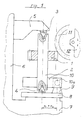
- the gear 1 to be machined - in the present case a spur gear - is firmly connected in a manner known per se to a holding mandrel 2 which in turn is clamped between tips 3 and 4 at its two ends.
- the upper tip 3 is mounted in a counter holder 5, which in turn is connected to a carriage 7 via a column 6.
- This carriage 7 carries out the translatory part of the rolling movement to be generated, here a movement perpendicular to the plane of the page. It carries on its upper side a turntable 8, which generates the rotary part of the rolling movement and which has the aforementioned tip 4 in its center and also radially distances one or more drivers 9.
- These drivers 9 are in play-free engagement with grooves 10a with one the drive plate 10 connected to the mandrel 2. In this way, a rolling movement is generated on the rotary table 8 and transmitted to the gear 1.
- the gear wheel is machined by a grinding wheel 11, which is mounted in a lifting carriage 12, which carries out a reciprocating, vertical lifting movement.
- This machine can also machine bevel gears with a small bevel angle.
- the lifting plane of the slide 12 is pivoted in accordance with the desired cone angle in the exemplary embodiment, ie within the leaf plane.
- FIGS. 2 and 3 The design according to the invention, in which these shortcomings are eliminated, is shown in FIGS. 2 and 3. Corresponding parts are provided with the same reference numerals.
- the mandrel 2 with its drive plate 10 can be pivoted out of its aligned position with the axis of rotation of the workpiece table 8, so that the cone angle ⁇ can be set between the axis of the gear wheel 1 and the axis of the rotary table 8.
- the plane of movement of the lifting carriage 12 remains vertical, that is, in a plane parallel to the axis of the rotary table 8.
- the angle of the mandrel 2 is adjusted by dividing the counter-holder 5 into a base body 5a mounted on the column 6 on the one hand and a slide 5b on the other hand, which can be moved along guides 5c approximately in the grinding wheel plane on the base body 5a and can be locked in the desired position.
- the storage of the mandrel 2 differs in that instead of the tips 3 and 4 balls 3a and 4a are provided and that the upper ball 3a is under vertical pressure so that the mandrel is guided without play even in the deflected state.
- the angular difference between the axes of the gear wheel 1 and the rotary table 8 leads to the fact that, with the rotary drive of the table 8 being uniform, the drive plate 10 has an acceleration phase to ⁇ max and a deceleration phase to ⁇ min during each revolution, given the constant angular velocity of the drive shaft denotes ⁇ .
- Figure 3 shows the storage of the grinding carriage 12. It is mounted along guides 13 on a grinding carriage 14 vertically movable.
- the Grinding slide carrier 14 in turn, is pivotally mounted on the stand 16 about a horizontal axis that intersects the axis of the rotary table 8 perpendicularly, the position of which at least approximately corresponds to the axis of the virtual face wheel.
- the grinding carriage carrier 14 performs a reciprocating short-stroke pivoting movement about this axis, which corresponds to the rotational and translational movement of the gearwheel and is part of the common rolling movement.
- the track of the grinding wheel is shifted as a result, to the extent that the generating face wheel rotates about its axis during the rolling process. This gives you an absolutely exact bevel gear.
- the grinding carriage 12 also has a horizontal guide 17.
- the grinding wheel 11 can be moved parallel to itself out of its aligned position with the gearwheel axis and can be fixed in the desired position.
- the grinding wheel has been moved out of its zero position by a transverse path B. This adjustment option is required if helical bevel gears are to be manufactured.
- the present invention also gives the possibility of a machine which until now has only been suitable for the precise machining of spur gears by simple and inexpensive conversion measures to be used for the precise production of straight or helical bevel gears.
- the machine is suitable for gearwheels with larger partial taper lengths, in which the previous, less precise production becomes particularly clear.
Abstract
Description
Die Erfindung betrifft eine Vorrichtung zum wahlweisen Bearbeiten von Stirn- oder Kegel-Zahnrädern mit einem das Zahnrad tragenden Werkstücktisch, der neben einer Drehbewegung eine translatorische hin und hergehende Bewegung durchführt und mit einem das Werkzeug tragenden Schlitten, der Hubbewegungen entlang den Zahnflanken des Zahnrades durchführt.The invention relates to a device for the optional machining of spur or bevel gears with a workpiece table carrying the gear, which carries out a translational reciprocating movement in addition to a rotary movement and with a carriage carrying the tool, which carries out lifting movements along the tooth flanks of the gear.
Derartige Maschinen sind in Form von Zahnflanken-Schleifmaschinen bekannt. Sie arbeiten vorzugsweise im Teilwälzverfahren mit einer Doppelkegelscheibe. Bei der Herstellung von Stirn-Zahnrädern führt der Schleifschlitten eine Hubbewegung parallel zur Zahnradachse durch, wogegen bei der Herstellung von Kegelrädern entweder die Hubebene des Schleifschlittens entsprechend dem Kegelwinkel geneigt wird oder man überlagert dem Schleifschlitten während der Hubbewegung eine radiale Bewegung, die durch eine Schablone oder CNC-Steuerung erzeugt wird. In beiden Fällen führt das Werkzeug also eine Hubbewegung schräg zur Zahnradachse durch, während die Zahnradachse mit der Achse des sie tragenden Drehtisches fluchtet.Such machines are known in the form of tooth flank grinding machines. You preferably work in the partial hobbing process with a double cone pulley. In the production of spur gear wheels, the grinding slide carries out a stroke movement parallel to the gear axis, whereas in the production of bevel gears, either the lifting plane of the grinding slide is inclined according to the cone angle or a radial movement is superimposed on the grinding slide during the stroke movement, which is carried out by a template or CNC control is generated. In both cases, the tool carries out a stroke movement obliquely to the gearwheel axis, while the gearwheel axis is aligned with the axis of the rotary table carrying it.
Untersuchungen der Anmelderin haben ergeben, daß eine geometrisch exakte Herstellung von Kegelrädern auf diese Weise nicht möglich ist, denn die Schrägstellung des Werkzeuges ändert nichts daran, daß seine Bewegung einen Erzeugungs-Wälzzylinder repräsentiert, bei dem der Grundkreis der Evolvente gleich bleibt. Man erhält somit nur eine Stirnradverzahnung mit einer sich über die Zahnbreite stetig ändernden Profilverschiebung.Investigations by the applicant have shown that a geometrically exact manufacture of bevel gears on these This is not possible, because the inclination of the tool does not change the fact that its movement represents a generating rolling cylinder in which the base circle of the involute remains the same. You only get a spur gear toothing with a profile shift that changes constantly over the tooth width.
Hiervon ausgehend liegt die Aufgabe der vorliegenden Erfindung darin, eine Bearbeitungsmaschine anzugeben, die einerseits optimal zum Bearbeiten von Stirn-Zahnrädern geeignet ist, andererseits aber durch einfache, kostengünstige Maßnahmen eine wesentlich genauere Herstellung von Kegel-Zahnrädern gestattet als dies bei den bisher bekannten kombinierten Maschinen möglich ist. In Weiterbildung der Erfindung soll auch eine geometrisch exakte Kegelradverzahnung realisierbar sein.Proceeding from this, the object of the present invention is to provide a processing machine which is on the one hand optimally suitable for machining spur gearwheels, but on the other hand allows simple, inexpensive measures to produce conical gearwheels much more precisely than in the previously known combined machines is possible. In a further development of the invention, geometrically exact bevel gear teeth should also be realizable.
Diese Aufgabe wird erfindungsgemäß dadurch gelöst, daß der Werkstücktisch eine winkeleinstellbare Aufnahme für das Zahnrad aufweist, derart, daß die Zahnradachse um einen gewünschten Kegelwinkel aus der Flucht mit der Werkstück-Tischachse herausschwenkbar und in dieser herausgeschwenkten Position feststellbar ist.This object is achieved in that the workpiece table has an angle-adjustable receptacle for the gear, such that the gear axis can be pivoted out of alignment with the workpiece table axis by a desired cone angle and can be locked in this pivoted-out position.
Die Erfindung beruht auf der Erkenntnis, daß die gegenüber der Tischachse schräg stehende Zahnrad-Drehachse eine Verzahnung mit über die Zahnbreite sich ständig ändernden Grundkreisen ergibt, wie dies bei Kegelverzahnungen der Fall sein soll, und daß dabei die Relativbewegung zwischen Werkzeug und Zahnrad so erfolgt, daß sie nicht mehr einem Wälzzylinder, sondern dem gewünschten Erzeugungs-Wälzkegel entspricht.The invention is based on the knowledge that the gear wheel axis of rotation, which is inclined with respect to the table axis, results in a toothing with basic circles that constantly change over the tooth width, as is the case with bevel gearings, and that the relative movement between the tool and the gear wheel takes place in this way, that it no longer corresponds to a rolling cylinder, but to the desired generating rolling cone.
Man erhält dadurch eine wesentlich präzisere Verzahnungsgeometrie und es lassen sich nunmehr auch Kegelwinkel deutlich über 10° realisieren.This results in a much more precise tooth geometry and it is now also possible to achieve taper angles well above 10 °.
Ein weiterer Vorteil der Erfindung besteht darin, daß die bisher notwendigen Schablonen oder die numerische Bahnsteuerung für den schrägen Bewegungsverlauf des Werkzeugschlittens entfallen. Darüber hinaus eröffnet dies die Möglichkeit, mit größeren Hubgeschwindigkeiten als bisher zu arbeiten.Another advantage of the invention is that the previously required templates or the numerical path control for the oblique movement of the tool slide are eliminated. In addition, this opens up the possibility of working with higher lifting speeds than before.
Für den Fachmann bieten sich verschiedene Möglichkeiten, um die Drehbewegung des Werkstücktisches auf die ihm gegenüber winkeleinstellbare Aufnahme für das Zahnrad zu übertragen. Grundsätzlich kommen hierfür Gleichgang-Gelenke in Betracht, die jede Verdrehung winkelgetreu, also mit konstantem Übersetzungsverhältnis übertragen. Derartige Gelenke sind jedoch wegen Ihres Platzbedarfes und ihres elastischen Verhaltens in Umfangsrichtung problematisch. Besonders zweckmäßig ist es daher, ein relativ einfaches, platzsparendes Gelenk zu verwenden, das zwar mit ungleichmäßiger Bewegungsübertragung behaftet ist, diese Ungleichförmigkeiten aber durch eine CNC-Steuerung des Werkstücktisch- Antriebes zu kompensieren. In diesem Fall kann das Gelenk dadurch gebildet sein, daß am Werkstücktisch nach oben vorstehende Kugeln angeordnet sind, die in passende Axialnuten der darüber befindlichen Aufnahme hineinragen.There are various possibilities for the person skilled in the art to transfer the rotary movement of the workpiece table to the receptacle for the gearwheel that is adjustable in relation to it. In principle, constant-velocity joints are considered for this, which transmit each rotation at an angle, i.e. with a constant transmission ratio. Such joints are problematic because of their space requirements and their elastic behavior in the circumferential direction. It is therefore particularly expedient to use a relatively simple, space-saving joint which, although it has uneven movement transmission, compensates for these irregularities by means of a CNC control of the workpiece table drive. In this case, the joint can be formed in that balls projecting upwards are arranged on the workpiece table and protrude into suitable axial grooves in the receptacle located above.
Im allgemeinen ist die Aufnahme mit einem das Zahnrad durchquerenden Dorn versehen, der an seinen beiden Enden eingespannt ist. In diesem Fall empfiehlt es sich, daß die eine Einspannstelle etwa senkrecht zur Achse des Werkstücktisches verstellbar ist, etwa indem der oberhalb des Werkstücktisches angeordnete Gegenhalter längs einer Horizontalführung verfahrbar und festklemmbar ist.In general, the receptacle is provided with a mandrel crossing the gear wheel, which is clamped at both ends. In this case it is recommended that the one clamping point is adjustable approximately perpendicular to the axis of the workpiece table, for example in that the counter-holder arranged above the workpiece table can be moved and clamped along a horizontal guide.
Der Dorn selbst wird vorteilhaft zwischen seinen beiden Einspannstellen durch zwei Kugeln zentriert, von denen die eine federnd angepreßt wird, damit die beim Schrägstellen des Dornes eintretende Erniedrigung seiner oberen Einspannstelle relativ zum Gegenhalter kompensiert wird.The mandrel itself is advantageously centered between its two clamping points by two balls, one of which is pressed resiliently, so that the lowering of its upper clamping point relative to the counterholder which occurs when the mandrel is inclined is compensated for.
In denjenigen Fällen, wo absolute Übereinstimmung mit der Verzahnungstheorie von Kegelrädern verlangt wird, kann in Weiterbildung der Erfindung der das Werkzeug tragende Schlitten zusätzlich zu seiner Hubbewegung eine mit der Wälzbewegung korrespondierende, hin und hergehende Schwenkbewegung um eine die Werkstück-Tischachse senkrecht schneidende, als Planradachse fungierende Schwenkachse durchführen. Diese Schwenkbewegung wird zweckmäßig in der Form realisiert, daß man den Werkzeugschlitten verschiebbar auf einem Träger lagert, der seinerseits schwenkbar am Ständer bzw. am Maschinenbett gelagert ist.In those cases where absolute agreement with the toothing theory of bevel gears is required, in a further development of the invention the slide carrying the tool can, in addition to its lifting movement, a reciprocating pivoting movement corresponding to the rolling movement about a plane wheel axis that perpendicularly intersects the workpiece table axis perform the acting swivel axis. This pivoting movement is expediently implemented in such a way that the tool slide is slidably mounted on a carrier which in turn is pivotably mounted on the stand or on the machine bed.
Durch die hin und hergehende Schwenkbewegung des Werkzeugschlittens, die mit der rotatorischen und translatorischen Bewegung des Zahnrades korrespondiert, wird das Werkzeug exakt so bewegt, daß es das virtuelle Erzeugungs-Planrad, wie es in der Verzahnungstheorie von Kegelrädern vorgeschrieben ist, repräsentiert.Due to the back and forth swiveling movement of the tool slide, which corresponds to the rotational and translational movement of the gear, the tool is moved exactly so that it represents the virtual generation face wheel, as prescribed in the toothing theory of bevel gears.
Weitere Merkmale und Vorteile der Erfindung ergeben sich aus der nachfolgenden Beschreibung eines Ausführungsbeispieles in Form einer Schleifmaschine; dabei zeigt
Figur 1- eine Seitenansicht auf einen Ausschnitt einer herkömmlichen Schleifmaschine;
Figur 2- eine Seitenansicht auf den gleichen Ausschnitt bei einer erfindungsgemäßen Schleifmaschine;
Figur 3- eine um 90° geklappte Seitenansicht auf den Schleifschlittenträger gemäß
Figur 2.
- Figure 1
- a side view of a section of a conventional grinding machine;
- Figure 2
- a side view of the same section in a grinding machine according to the invention;
- Figure 3
- a 90 ° folded side view of the grinding slide carrier according to Figure 2.
Zur Erläuterung wird zunächst eine herkömmliche Schleifmaschine anhand von Figur 1 beschrieben. Das zu bearbeitende Zahnrad 1 - im vorliegenden Fall ein Stirnrad - ist in an sich bekannter Weise fest mit einem Aufnahmedorn 2 verbunden, der seinerseits an seinen beiden Enden zwischen Spitzen 3 und 4 verspannt ist. Die obere Spitze 3 ist in einem Gegenhalter 5 gelagert, der seinerseits über eine Säule 6 mit einem Schlitten 7 verbunden ist. Dieser Schlitten 7 führt den translatorischen Anteil der zu erzeugenden Wälzbewegung durch, hier also eine Bewegung senkrecht zur Blattebene. Er trägt an seiner Oberseite einen Drehtisch 8, der den rotatorischen Anteil der Wälzbewegung erzeugt und der in seinem Zentrum die zuvor genannte Spitze 4 aufweist und außerdem radial davon distanziert einen oder mehrere Mitnehmer 9. Diese Mitnehmer 9 stehen in spielfreiem Eingriff mit Nuten 10a einer mit dem Dorn 2 verbundenen Mitnehmerscheibe 10. Auf diese Weise wird am Drehtisch 8 eine Wälzbewegung erzeugt und auf das Zahnrad 1 übertragen.To explain this, a conventional grinding machine will first be described with reference to FIG. 1. The
Die Bearbeitung des Zahnrades erfolgt durch eine Schleifscheibe 11, die in einem Hubschlitten 12 gelagert ist, der eine hin und hergehende, vertikale Hubbewegung durchführt.The gear wheel is machined by a grinding
Mit dieser Maschine können auch Kegelräder mit geringem Kegelwinkel bearbeitet werden. Dazu wird die Hubebene des Schlittens 12 entsprechend dem gewünschten Kegelwinkelim Ausführungsbeispiel also innerhalb der Blattebene - verschwenkt. Es kommt dabei jedoch zu den in der Beschreibungseinleitung genannten Unzulänglichkeiten, weil der Bewegungsablauf nicht der Verzahnungsgeometrie von Kegelrädern gerecht wird.This machine can also machine bevel gears with a small bevel angle. For this purpose, the lifting plane of the
Die erfindungsgemäße Bauform, bei der diese Unzulänglichkeiten beseitigt sind, ist in den Figuren 2 und 3 abgebildet. Einander entsprechende Teile sind dabei mit den gleichen Bezugszeichen versehen.The design according to the invention, in which these shortcomings are eliminated, is shown in FIGS. 2 and 3. Corresponding parts are provided with the same reference numerals.
Im Unterschied zu Figur 1 ist hier der Dorn 2 mit seiner Mitnehmerscheibe 10 aus seiner fluchtenden Position mit der Drehachse des Werkstücktisches 8 herauszuschwenken, so daß zwischen der Achse des Zahnrades 1 und der Achse des Drehtisches 8 der Kegelwinkel δ eingestellt werden kann. Die Bewegungsebene des Hubschlittens 12 bleibt dabei nach wie vor in der Vertikalen, also in einer Ebene parallel zur Achse des Drehtisches 8.In contrast to Figure 1, the
Die Neigungsverstellung des Dornes 2 erfolgt durch eine Teilung des Gegenhalters 5 in einen an der Säule 6 montierten Grundkörper 5a einerseits und einen Schlitten 5b andererseits, der längs Führungen 5c etwa in der Schleifscheibenebene auf dem Grundkörper 5a verfahrbar und in der gewünschten Position feststellbar ist.The angle of the
Des weiteren unterscheidet sich die Lagerung des Dornes 2 dadurch, daß anstelle der Spitzen 3 und 4 Kugeln 3a und 4a vorgesehen sind und daß die obere Kugel 3a unter vertikaler Anpressung steht, damit der Dorn auch in ausgelenktem Zustand spielfrei geführt wird.Furthermore, the storage of the
Die Winkeldifferenz zwischen den Achsen des Zahnrades 1 und des Drehtisches 8 führt dazu, daß bei gleichförmigem Drehantrieb des Tisches 8 die Mitnehmerscheibe 10 wegen der kardanischen Bewegungsübertragung während jeder Umdrehung eine Beschleunigungsphase auf ωmax und eine Verzögerungsphase auf ωmin, wenn man die konstante Winkelgeschwindigkeit der Antriebswelle mit ω bezeichnet.The angular difference between the axes of the
Um die ungleichförmige Drehung des Zahnrades zu eliminieren, werden die beim Abtrieb sich ergebenden Ungleichmäßigkeiten mit negativem Vorzeichen dem Antrieb des Drehtisches 8 auferlegt. Die Bewegungsgleichung für die Drehung des Tisches 8 lautet also
![]()
- ω
- Winkelgeschwindigkeit des Werkstücktisches
- t
- Zeitparameter
- A
- Konstante entsprechend Kegelwinkel δ und konstruktiver Abmessungen
- ω
- Angular speed of the workpiece table
- t
- Time parameters
- A
- Constant corresponding to cone angle δ and structural dimensions
Figur 3 zeigt die Lagerung des Schleifschlittens 12. Er ist längs Führungen 13 auf einem Schleifschlittenträger 14 vertikal verfahrbar gelagert. Darüber hinaus ist der Schleifschlittenträger 14 seinerseits um eine die Achse des Drehtisches 8 senkrecht schneidende Horizontalachse, deren Position zumindest annähernd der Achse des virtuellen Planrades entspricht, schwenkbar am Ständer 16 gelagert. Der Schleifschlittenträger 14 führt um diese Achse eine hin und hergehende kurzhubige Schwenkbewegung durch, die mit der rotatorischen und translatorischen Bewegung des Zahnrades korrespondiert und Teil der gemeinsamen Wälzbewegung ist. Die Spur der Schleifscheibe wird dadurch verlagert, und zwar in dem Maße, wie sich das erzeugende Planrad um seine Achse während des Abwälzvorganges verdreht. Man erhält dadurch eine absolut exakte Kegelverzahnung.Figure 3 shows the storage of the grinding
Nimmt man eine Näherung der Zahnform in Kauf oder geht es um das Schleifen gewöhnlicher Stirnräder, so entfällt die Schwenkbewegung des Schleifschlittenträgers 14.If an approximation of the tooth shape is accepted or if it is a matter of grinding ordinary spur gears, then the pivoting movement of the grinding
Schließlich weist der Schleifschlitten 12 noch eine Horizontalführung 17 auf. Dadurch kann die Schleifscheibe 11 parallel zu sich selbst aus ihrer fluchtenden Position mit der Zahnradachse herausgefahren und in der gewünschten Position festgestellt werden. In Figur 3 ist die Schleifscheibe um einen Querweg B aus Ihrer Nullstellung herausgefahren. Man benötigt diese Verstellmöglichkeit, wenn schräg verzahnte Kegelräder hergestellt werden sollen.Finally, the grinding
Zusammenfassend erhält man also durch die vorliegende Erfindung die Möglichkeit, eine Maschine, die bis jetzt nur zur präzisen Bearbeitung von Stirnrädern geeignet ist, durch einfache und kostengünstige Umrüstmaßnahmen auch für die präzise Fertigung von gerad- oder schrägverzahnten Kegelrädern zu verwenden. Insbesondere ist die Maschine für Zahnräder mit größeren Teilkegellängen geeignet, bei denen die bisherige, weniger genaue Fertigung besonders deutlich wird.In summary, the present invention also gives the possibility of a machine which until now has only been suitable for the precise machining of spur gears by simple and inexpensive conversion measures to be used for the precise production of straight or helical bevel gears. In particular, the machine is suitable for gearwheels with larger partial taper lengths, in which the previous, less precise production becomes particularly clear.
Claims (10)
dadurch gekennzeichnet,
daß der Werkstücktisch (8) eine winkeleinstellbare Aufnahme (2, 10) für das Zahnrad (1) aufweist, derart, daß die Zahnradachse um einen gewünschten Kegelwinkel (δ) aus der Flucht mit der Werkstück-Tischachse herausschwenkbar und in der herausgeschwenkten Position feststellbar ist.Device for the optional machining of spur or bevel gearwheels with a workpiece table (8) carrying the gearwheel (1), which carries out a translational reciprocating movement in addition to a rotary movement and with a slide (12) carrying the tool (11) Performs lifting movements along the tooth flanks of the gear wheel (1),
characterized,
that the workpiece table (8) has an angle-adjustable receptacle (2, 10) for the gear (1), such that the gear axis can be pivoted out of alignment with the workpiece table axis by a desired cone angle (δ) and can be locked in the pivoted-out position .
dadurch gekennzeichnet,
daß die winkeleinstellbare Aufnahme (2, 10) für das Zahnrad (1) durch ein Gleichgang-Gelenk drehfest mit dem Werkstücktisch (8) verbunden ist.Device according to claim 1,
characterized,
that the angle-adjustable receptacle (2, 10) for the gear (1) is rotatably connected to the workpiece table (8) by a constant velocity joint.
dadurch gekennzeichnet,
daß die winkeleinstellbare Aufnahme (2, 10) durch ein Gelenk (9, 10a) mit ungleichmäßiger Bewegungsübertragung drehfest mit dem Werkstücktisch (8) verbunden ist und daß Ungleichförmigkeiten der Bewegungsübertragung durch eine CNC-Steuerung des Werkstücktisch-Antriebes kompensiert sind.Device according to claim 1,
characterized,
that the angle-adjustable receptacle (2, 10) by a joint (9, 10a) with uneven transmission of movement is rotatably connected to the workpiece table (8) and that irregularities in the transmission of movement are compensated by a CNC control of the workpiece table drive.
dadurch gekennzeichnet,
daß die drehfeste Verbindung zwischen den genannten Teilen (8;2) durch am Werkstücktisch (8) angeordnete Kugeln (9) erfolgt, die in passende Nuten (10a) der Aufnahme (2, 10) hineinragen.Device according to claim 3,
characterized,
that the rotationally fixed connection between said parts (8; 2) takes place by balls (9) arranged on the workpiece table (8), which project into suitable grooves (10a) of the receptacle (2, 10).
dadurch gekennzeichnet,
daß die eine Einspannstelle (3a) etwa senkrecht zur Achse des Werkstücktisches (8) verstellbar ist.Device according to one of the preceding claims, wherein the receptacle (2, 10) has a mandrel (2) which traverses the gearwheel (1) and is clamped near its two ends,
characterized,
that the one clamping point (3a) is adjustable approximately perpendicular to the axis of the workpiece table (8).
dadurch gekennzeichnet,
daß die verstellbare Einspannstelle (3a) durch einen dem Werkstücktisch gegenüberliegenden Schlitten (5b) gebildet ist, der längs einer Horizontalführung (5c) an einem Gegenhalter (5a) verfahrbar und festklemmbar ist.Device according to claim 5,
characterized,
that the adjustable clamping point (3a) is formed by a slide (5b) opposite the workpiece table, which can be moved and clamped along a horizontal guide (5c) on a counter-holder (5a).
dadurch gekennzeichnet,
daß der Dorn (2) zwischen seinen Einspannstellen durch zwei Kugeln (3a, 4a) zentriert ist, von denen die eine federnd angepreßt ist.Apparatus according to claim 5 or 6,
characterized,
that the mandrel (2) is centered between its clamping points by two balls (3a, 4a), one of which is pressed resiliently.
dadurch gekennzeichnet,
daß der das Werkzeug (11) tragende Schlitten (12) zusätzlich zu seiner Hubbwegung eine hin und hergehende Schwenkbewegung um eine die Werkstück-Tischachse senkrecht schneidende, als Planradachse fungierende Schwenkachse (15) durchführt.Device according to claim 1,
characterized,
that the carriage (12) carrying the tool (11) performs, in addition to its stroke movement, a reciprocating pivoting movement about a pivot axis (15) which cuts perpendicularly to the workpiece table axis and acts as a face wheel axis.
dadurch gekennzeichnet,
daß der Werkzeugschlitten (12) zur Realisierung der vorgenannten Schwenkbewegung verschiebbar auf einem Träger (14) geführt ist, der seinerseits um die Achse (15) schwenkbar am Maschinenbett (16) gelagert ist.Device according to claim 8,
characterized,
that the tool slide (12) is slidably guided to carry out the aforementioned pivoting movement on a carrier (14) which in turn is pivotally mounted on the machine bed (16) about the axis (15).
dadurch gekennzeichnet,
daß der Werkzeugschlitten (12) eine Verschiebung des Werkzeuges senkrecht zu seiner Hubrichtung gestattet.Device according to claim 1,
characterized,
that the tool slide (12) allows a displacement of the tool perpendicular to its stroke direction.
Applications Claiming Priority (2)
| Application Number | Priority Date | Filing Date | Title |
|---|---|---|---|
| DE4208046 | 1992-03-13 | ||
| DE19924208046 DE4208046A1 (en) | 1992-03-13 | 1992-03-13 | DEVICE FOR MACHINING FRONT OR CONE GEARS |
Publications (1)
| Publication Number | Publication Date |
|---|---|
| EP0560065A1 true EP0560065A1 (en) | 1993-09-15 |
Family
ID=6453989
Family Applications (1)
| Application Number | Title | Priority Date | Filing Date |
|---|---|---|---|
| EP93101984A Withdrawn EP0560065A1 (en) | 1992-03-13 | 1993-02-09 | Device for machining cylindrical or bevel gears |
Country Status (2)
| Country | Link |
|---|---|
| EP (1) | EP0560065A1 (en) |
| DE (1) | DE4208046A1 (en) |
Cited By (2)
| Publication number | Priority date | Publication date | Assignee | Title |
|---|---|---|---|---|
| CN102248229A (en) * | 2011-06-07 | 2011-11-23 | 无锡市瑞尔精密机械股份有限公司 | Face tooth grinding fixture |
| CN102728904A (en) * | 2012-03-22 | 2012-10-17 | 浙江嘉力宝精机股份有限公司 | Numeric control forming gear grinding machine |
Citations (4)
| Publication number | Priority date | Publication date | Assignee | Title |
|---|---|---|---|---|
| DE277514C (en) * | ||||
| US2114690A (en) * | 1934-10-12 | 1938-04-19 | William E Sykes | Machine for generating tapered gears |
| US3877150A (en) * | 1971-02-25 | 1975-04-15 | Hoefler Willy | Gear generating machine for making and testing involute gears |
| US4872791A (en) * | 1988-06-27 | 1989-10-10 | Dynetics, Inc. | Method of forming crowned gear teeth |
-
1992
- 1992-03-13 DE DE19924208046 patent/DE4208046A1/en not_active Withdrawn
-
1993
- 1993-02-09 EP EP93101984A patent/EP0560065A1/en not_active Withdrawn
Patent Citations (4)
| Publication number | Priority date | Publication date | Assignee | Title |
|---|---|---|---|---|
| DE277514C (en) * | ||||
| US2114690A (en) * | 1934-10-12 | 1938-04-19 | William E Sykes | Machine for generating tapered gears |
| US3877150A (en) * | 1971-02-25 | 1975-04-15 | Hoefler Willy | Gear generating machine for making and testing involute gears |
| US4872791A (en) * | 1988-06-27 | 1989-10-10 | Dynetics, Inc. | Method of forming crowned gear teeth |
Cited By (3)
| Publication number | Priority date | Publication date | Assignee | Title |
|---|---|---|---|---|
| CN102248229A (en) * | 2011-06-07 | 2011-11-23 | 无锡市瑞尔精密机械股份有限公司 | Face tooth grinding fixture |
| CN102728904A (en) * | 2012-03-22 | 2012-10-17 | 浙江嘉力宝精机股份有限公司 | Numeric control forming gear grinding machine |
| CN102728904B (en) * | 2012-03-22 | 2014-11-19 | 浙江嘉力宝精机股份有限公司 | Numeric control forming gear grinding machine |
Also Published As
| Publication number | Publication date |
|---|---|
| DE4208046A1 (en) | 1993-09-16 |
Similar Documents
| Publication | Publication Date | Title |
|---|---|---|
| EP0501196B1 (en) | Fully automatic gear cutting machine for making gears having longitudinally curved teeth and method of operating the machine | |
| EP0097346A2 (en) | Method and apparatus for making work-pieces with an internal or external polygonal surface | |
| EP0135709A1 (en) | Method of manufacturing parts with polygonal outer and/or inner profiles, and devices for carrying out the method | |
| EP0568849B1 (en) | Method for finishing crowned and/or conical gear teeth and machine for carrying out this method | |
| DE4313535A1 (en) | Five-axis gear-cutting machine for producing spiral gears, and method of operating the machine | |
| EP0192817B1 (en) | Device for the teeth-finishing treatment of gear wheels | |
| DE2516059A1 (en) | DEVICE FOR THE MANUFACTURING OR MACHINING OF SPUR WHEELS | |
| EP0560065A1 (en) | Device for machining cylindrical or bevel gears | |
| DD279627A1 (en) | METHOD AND DEVICE FOR PRODUCING STRAIGHT OR CROWNED HEADDRESSES WITH LENGTH AND HEAVY BALLIFIED MODIFIED TOOTHED FLANKS | |
| DE2434636C3 (en) | Machine for grinding trochoid surfaces | |
| DE4134925C1 (en) | Gear wheel machining fixture - has two cutter spindles with cutter head moving at angles | |
| EP0516865A1 (en) | Milling machine | |
| DE1203576B (en) | Device for whirling tooth gaps or grooves on cylindrical bodies that run at an angle of 45 to 90íÒ to the cylinder axis | |
| DE4305810C1 (en) | Tool-head turret type rotary table grinding machine - has alternative worm and wheel reduction gear drive to worktable which is engaged to permit accurate rotational positioning when milling station of turret is used. | |
| CH341088A (en) | Method for shaping a working surface, which has a helical course, of a grinding wheel which is used for machining gears and the like according to the rolling principle, and a machine for performing the method | |
| DE1075922B (en) | Method and device for non-cutting deburring of the teeth and / or for producing bevels on the tooth edges of toothed wheels and other toothed workpieces | |
| DE3822487C1 (en) | Method and device for producing curved paths on a workpiece | |
| DE615921C (en) | Working method for engraving or copying machines with pantograph system | |
| DE2004222A1 (en) | Device for finishing pre-toothed gears | |
| DE4130736A1 (en) | Profile grinding machine tool | |
| DE3410575A1 (en) | Polygonal turning machine | |
| EP1092495A1 (en) | Gear grinding generator with gear measuring device | |
| DD212670A1 (en) | DEVICE FOR PROFILE GRINDING ROTATION SYMMETRIC WORKSTUECKE | |
| DE2421670A1 (en) | Machine for generating gears with convex teeth - rolls conventionally cut gears in inclined position between generating tools | |
| DE755757C (en) | Bevel gear planer working according to the rolling process |
Legal Events
| Date | Code | Title | Description |
|---|---|---|---|
| PUAI | Public reference made under article 153(3) epc to a published international application that has entered the european phase |
Free format text: ORIGINAL CODE: 0009012 |
|
| AK | Designated contracting states |
Kind code of ref document: A1 Designated state(s): CH DE IT LI |
|
| STAA | Information on the status of an ep patent application or granted ep patent |
Free format text: STATUS: THE APPLICATION HAS BEEN WITHDRAWN |
|
| 18W | Application withdrawn |
Withdrawal date: 19931018 |