EP0559120A1 - Procédé et dispositif pour mesurer des distances - Google Patents
Procédé et dispositif pour mesurer des distances Download PDFInfo
- Publication number
- EP0559120A1 EP0559120A1 EP93103234A EP93103234A EP0559120A1 EP 0559120 A1 EP0559120 A1 EP 0559120A1 EP 93103234 A EP93103234 A EP 93103234A EP 93103234 A EP93103234 A EP 93103234A EP 0559120 A1 EP0559120 A1 EP 0559120A1
- Authority
- EP
- European Patent Office
- Prior art keywords
- light spot
- radiation
- distance
- measuring head
- emitted
- Prior art date
- Legal status (The legal status is an assumption and is not a legal conclusion. Google has not performed a legal analysis and makes no representation as to the accuracy of the status listed.)
- Granted
Links
Images


Classifications
-
- G—PHYSICS
- G01—MEASURING; TESTING
- G01S—RADIO DIRECTION-FINDING; RADIO NAVIGATION; DETERMINING DISTANCE OR VELOCITY BY USE OF RADIO WAVES; LOCATING OR PRESENCE-DETECTING BY USE OF THE REFLECTION OR RERADIATION OF RADIO WAVES; ANALOGOUS ARRANGEMENTS USING OTHER WAVES
- G01S17/00—Systems using the reflection or reradiation of electromagnetic waves other than radio waves, e.g. lidar systems
- G01S17/02—Systems using the reflection of electromagnetic waves other than radio waves
- G01S17/06—Systems determining position data of a target
- G01S17/08—Systems determining position data of a target for measuring distance only
- G01S17/32—Systems determining position data of a target for measuring distance only using transmission of continuous waves, whether amplitude-, frequency-, or phase-modulated, or unmodulated
-
- G—PHYSICS
- G01—MEASURING; TESTING
- G01B—MEASURING LENGTH, THICKNESS OR SIMILAR LINEAR DIMENSIONS; MEASURING ANGLES; MEASURING AREAS; MEASURING IRREGULARITIES OF SURFACES OR CONTOURS
- G01B11/00—Measuring arrangements characterised by the use of optical techniques
- G01B11/02—Measuring arrangements characterised by the use of optical techniques for measuring length, width or thickness
- G01B11/026—Measuring arrangements characterised by the use of optical techniques for measuring length, width or thickness by measuring distance between sensor and object
-
- G—PHYSICS
- G01—MEASURING; TESTING
- G01S—RADIO DIRECTION-FINDING; RADIO NAVIGATION; DETERMINING DISTANCE OR VELOCITY BY USE OF RADIO WAVES; LOCATING OR PRESENCE-DETECTING BY USE OF THE REFLECTION OR RERADIATION OF RADIO WAVES; ANALOGOUS ARRANGEMENTS USING OTHER WAVES
- G01S7/00—Details of systems according to groups G01S13/00, G01S15/00, G01S17/00
- G01S7/48—Details of systems according to groups G01S13/00, G01S15/00, G01S17/00 of systems according to group G01S17/00
- G01S7/481—Constructional features, e.g. arrangements of optical elements
- G01S7/4811—Constructional features, e.g. arrangements of optical elements common to transmitter and receiver
Definitions
- the invention relates to a method and a device for measuring the distance of the type specified in the respective preamble of claims 1 (method) and 9 (device).
- interferometry For the precise measurement of distances between an object, e.g. B. the surface of a clamped workpiece, and a reference point, various measuring principles are known, which can be divided into interferometry, runtime methods, focus search and triangulation (cf. TC Strand, "Optical three-dimensional sensing for machine vision", Opt. Eng. 24 , 33 (1985)). Since interferometry is not suitable for optically diffusely scattering surfaces, as they occur in mechanical engineering, and runtime measurements are too imprecise, most commercially used distance sensors are based on triangulation or focus search. These two methods are physically similar and are also subject to the same physical restrictions.
- the most widespread distance sensor is based on the principle shown schematically in FIG. 1.
- a light spot 2 is then projected onto an object 4 as an image of a light source 1 in the direction of the illumination axis 3. That at the Coherent light reflected from the object surface is collected in a measuring head 5 in the direction of the observation axis 6, which is inclined at a triangulation angle ⁇ with respect to the illumination axis, in a light spot image 7 on a photoreceiver 8.
- the measuring distance is determined by triangulation.
- a change in the distance of the object surface with the light spot 2 by a distance ⁇ z causes a measurable lateral displacement ⁇ x of the light spot image 7 to position 9.
- the accuracy of the distance determination is given by the accuracy of the position determination of the light spot image 7 or 9, which, however, is fundamentally limited by physical limits.
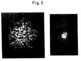
- the reason for this limitation lies in the statistical "speckle structure" of the light spot image, as shown in FIG. 2. Speckle noise essentially arises - even when illuminated with so-called incoherent sources - because in the elementary act of scattering, every excited atom emits light whose phase is correlated with that of the exciting light, whereby the exciting and the scattered light are capable of interference or 'coherent' with each other. This is also the case with the scattering of sunlight on objects, as is the case with the known distance sensors.
- the coherence function becomes wider when light is propagated, even the light of an incandescent lamp at the location of an illuminated object surface is not completely spatially incoherent, ie closely adjacent surface elements are illuminated in a phase-correlated manner. In the case of coherent scattering, the reflected light from two adjacent surface points is practically always capable of interference.
- the structure shown in FIG. 2 is determined by the respective microtopography of the object surface and has the consequence that the respective light spot image can only be detected with statistical uncertainty, which also impairs the accuracy of the distance determination.
- ⁇ x means the statistical uncertainty (standard deviation) of the lateral localization of the light spot, ⁇ the wavelength and sin u the observation aperture.
- ⁇ z means the measurement uncertainty (standard deviation) of the lateral localization of the light spot, ⁇ the wavelength and sin u the observation aperture.
- the measurement uncertainty based on speckle is calculated according to equation (3): ⁇ z ⁇ ⁇ / sin2u (3), which corresponds to the classic depth of field according to Rayleigh.
- the sensor therefore shows a very good range resolution. However, this only applies to object shifts that are small compared to the depth of field of the observation, since only then will the speckle structure be preserved.
- the sensor should display the same distance regardless of the movement. However, this is not the case.
- the sensor signal simulates the presence of a "mountainous" surface, as shown in FIG. 3, with a standard deviation of the height, which is given by equations (2) and (3).
- This standard deviation ⁇ z is not the surface roughness of the object surface, as is sometimes claimed. ⁇ z has nothing at all to do with the microtopography of the surface, but is determined exclusively by an apparatus property, the observation aperture, and can be a multiple of the object roughness.
- the radiation used to measure the distance encoding should be largely spatially incoherent.
- a (small) incoherent point source e.g. B. depicts a high-pressure mercury sheet on the object.
- the width of the spatial coherence function on the object is equal to the width of the diffraction image (point image) of the illuminating optics (M. Born, E. Wolf, “Prinziples of optics", Pergamonn Press, New York, 1970) .
- point image the diffraction image of the illuminating optics
- the above-described impairment of a highly accurate distance determination by the "speckle structure" The light spot images obtained also exist in a measuring device known from DE-A-33 42 675 for the optical scanning of workpieces according to the triangulation principle.
- a light spot is projected from one or two projectors at an angle onto the surface of the measurement object and the shift in the light spot image that occurs when the distance to the object changes is determined with a light-sensitive detector.
- the shape and the area of the light spot are also measured by means of image analysis.
- the coherent radiation of the illuminated light spot is evaluated, the measurement inaccuracies caused by the speckle structure of the light spot image also result here.
- the object of the invention is to provide a method and a device for determining the distance, in which the limitations of the prior art are eliminated and with which highly precise measurement results can be obtained with technically simple means.
- the object itself is excited by the electromagnetic radiation in a locally limited area to emit radiation which is not coherent with the exciting radiation. It is also the radiation of closely spaced atoms on the object surface does not correlate, ie the excited light spot radiates spatially and generally incoherently. Since, furthermore, according to the invention only this incoherent radiation emitted by the light spot is evaluated for the distance determination, no speckle structure occurs in the light spot image, which enables a more precise position determination of the light spot image and thus also a much more precise distance determination.
- An advantageous embodiment is characterized in that the object in the light spot from the radiation source, for. B. a laser, locally heated so much that it emits thermal (Planckian) radiation. This is spatially and temporally incoherent. Another possibility is the excitation of luminescence, which is composed of fluorescence and phosphorescence. Raman scattering as well as Brillouin scattering or other incoherent scattering mechanisms are also possible.
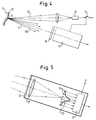
- a suitable small light source 10 generates a light spot 2 in or on the object 11.
- the light source 10 can be a thermal source, such as an incandescent lamp, a gas discharge lamp, a light-emitting diode, a gas or semiconductor laser and a superluminescent diode. It is essential that the radiation 13 of the light source 10 is suitable for exciting the surface of the object in the light spot 2 to incoherent radiation 14. Many organic materials show e.g. B. luminescence (fluorescence and phosphorescence) or Raman scattering or Brillouin scattering if they are excited with the correct wavelength. If the object does not emit incoherent radiation, the surface can be activated by suitable treatment, e.g. B. by coating with suitable phosphors 12. Often, small organic surface impurities are sufficient to excite the surface to incoherent emission.
- the hot focal spot generated by the laser beam in or on the object emits the incoherent radiation required for determining the distance.
- Local heating of the object surface which is sufficiently high to emit incoherent radiation, also occurs in other methods of material processing, such as arc welding.
- the spatially incoherent radiation emitted by the object 11 14 is collected in a measuring head 15 and evaluated in order to determine the distance to the object.
- the coherent portion 13a of the radiation 13 also emitted by the object 11 is separated from the emitted incoherent radiation portion 14 before the evaluation. This separation is possible using an optical color filter 16 because the incoherent radiation is usually in a different wavelength range than the coherent radiation.
- Another possibility is to choose the spectral sensitivity of the photoreceiver so that the coherent radiation component 13a is not detected.
- Another possibility is to interrupt the exciting radiation 13 after a certain time and to carry out the evaluation of the incoherent radiation 14 only after this. This possibility is symbolically represented in FIG. 4 by a switch 17, controlled by the measuring head 15, in front of the light source 10. Since the incoherent excited radiation can also be transmitted with a delay, depending on the choice of the excited material, the incoherent radiation can be evaluated within a time window, the start and end of which can advantageously be set.
- a triangulation measuring head is shown as an example, which contains an imaging line 18 and a locally resolving photo receiver, preferably a 'position-sensitive photodiode' (PSD) or a CCD photodiode array 19 shown in FIG. 5. 5, the individual diodes of such an array 19 are indicated.
- PSD 'position-sensitive photodiode'
- CCD photodiode array 19 shown in FIG. 5. 5
- the individual diodes of such an array 19 are indicated.
- the location of the spot image, its intensity distribution is reproduced as an example at item 20, encodes the distance to the object 11.
- the location of the light spot image can now be determined with extreme accuracy because the shape of the light spot image is not statistically disturbed by speckle.
- the position of the light spot image can also be determined much more precisely than its diameter or also much more precisely than given by the distance between the CCD photodiodes.
- the evaluation can take place in such a way that the three or five highest photodiode signals are used to fit a Gaussian curve or other suitable curve into the measured values.
- the location of the maximum of the fitted curve is a measure of the position of the light spot image. The possible accuracy is now essentially only influenced by the noise of the photo receiver.
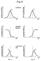
- the independence of the distance measurement from possible shape variations of the light spot image is solved according to the invention by the following method, such as. B. shown in Fig. 7.
- the location of the light spot image itself is not determined according to FIG. 7, but at least two shape-matched light spot images 25 and 26 are generated and the distance s between these two shape-matched light spot images Images 25, 26 are measured. It is thus possible to find the distance s between characteristic homologous points x 1, x 1 'or x 2, x 2', etc. in these images, as indicated in FIG. 7. Out the exact position of the homologous points, as can be determined in an evaluation unit 27, the distance s and thus the object distance can be evaluated.
- the homologous points can e.g. B. local maxima or minima. But you can also determine the center of gravity of the light spot image and determine the distance of the center of gravity of the different light spot images in order to determine the object distance from it.
- a correlation of the light spot images 25, 26 can also be carried out and the distance s can be calculated therefrom in a known manner.
- FIGS. 8 to 10 Two versions of such a measuring device are shown in FIGS. 8 to 10.
- the radiation 13 generated in the light source 2 is reflected at a splitter mirror 28 towards the object 11.
- the incoherent radiation 14 re-emitted in the light spot 2 passes through the color filter 16 and a converging lens 30.
- Behind this converging lens 30 there is a diaphragm 32 having a plurality of spaced openings, which in the embodiment according to FIG. 8 is designed as a double slit diaphragm. Apertures with several different openings are also possible.
- the distance s of the blurred light spot images depends on the distance z of the light spot 2 from the lens 30.
- the change in distance ⁇ s of the unsharp luminous spot images 25, 26 can be calculated as follows.
- ⁇ ⁇ 1.
- the unsharp luminous spot images 25, 26 are not mirror-symmetrical to the optical axis, but each have the same orientation as shown in FIG. 8, so that the distance between homologous points becomes independent of the shape .
- the unsharp luminous spot images 25, 26 also appear as an unsharp projection of the pupil, they are slit-shaped in the example above. This is somewhat disadvantageous since the photodetector should then take up such a large area that all of the light is captured.
- the use of a photodiode array, which is used in conjunction with a cylinder converging lens 33 shown in FIG. 8, is cheaper and better for faster evaluation.
- This cylinder converging lens 33 is oriented in such a way that the unsharp slit projections are drawn together approximately at one point, as shown in FIG. 9. This enables the use of a line-shaped photo receiver instead of a flat photo receiver without losses.
- a further embodiment for generating two or more identical light spot images, the mutual distance of which depends on the object distance, results from the use of a birefringent element through which the light of the light spot passes.
- a birefringent element through which the light of the light spot passes.
- Incoherent radiation generated in the light spot 2 for example by a Savart plate 36, with an upstream polarizer 37 and a downstream polarizer 38.
- This arrangement generates two virtual double images of the light spot at points 39 and 40, at a distance p, through the Savart plate 36 is given.
- the light from these double images comes to interference in a plane 41 behind the Savart plate. Interference fringes 42 can be observed there.
- the distance l of the interference fringes is determined and the object distance is derived from them.
Landscapes
- Physics & Mathematics (AREA)
- Engineering & Computer Science (AREA)
- General Physics & Mathematics (AREA)
- Computer Networks & Wireless Communication (AREA)
- Radar, Positioning & Navigation (AREA)
- Remote Sensing (AREA)
- Electromagnetism (AREA)
- Measurement Of Optical Distance (AREA)
- Length Measuring Devices By Optical Means (AREA)
Applications Claiming Priority (2)
| Application Number | Priority Date | Filing Date | Title |
|---|---|---|---|
| DE4206499 | 1992-03-02 | ||
| DE4206499A DE4206499C2 (de) | 1992-03-02 | 1992-03-02 | Verfahren und Vorrichtung zur Abstandsmessung |
Publications (2)
| Publication Number | Publication Date |
|---|---|
| EP0559120A1 true EP0559120A1 (fr) | 1993-09-08 |
| EP0559120B1 EP0559120B1 (fr) | 1996-06-19 |
Family
ID=6453012
Family Applications (1)
| Application Number | Title | Priority Date | Filing Date |
|---|---|---|---|
| EP93103234A Expired - Lifetime EP0559120B1 (fr) | 1992-03-02 | 1993-03-01 | Procédé et dispositif pour mesurer des distances |
Country Status (5)
| Country | Link |
|---|---|
| US (1) | US5486926A (fr) |
| EP (1) | EP0559120B1 (fr) |
| JP (1) | JP3547772B2 (fr) |
| DE (2) | DE4206499C2 (fr) |
| ES (1) | ES2090735T3 (fr) |
Cited By (8)
| Publication number | Priority date | Publication date | Assignee | Title |
|---|---|---|---|---|
| EP0657714A2 (fr) * | 1993-12-06 | 1995-06-14 | CENTRE DE RECHERCHES METALLURGIQUES CENTRUM VOOR RESEARCH IN DE METALLURGIE Association sans but lucratif | Procédé et dispositif pour mesurer le profil du flanc d'une bobine de bande |
| WO1995023346A1 (fr) * | 1994-02-23 | 1995-08-31 | Newnes Machine Ltd. | Procede et appareil permettant d'optimiser une resolution sub-pixellaire dans un dispositif de mesure de distance par triangulation |
| EP1816488A1 (fr) | 2006-02-07 | 2007-08-08 | Leuze electronic GmbH + Co. KG | Dispositif optoélectronique et son procédé de fonctionnement |
| EP1845334A1 (fr) * | 2006-04-11 | 2007-10-17 | Leuze electronic GmbH + Co. KG | Capteur optique |
| WO2011127617A1 (fr) * | 2010-04-13 | 2011-10-20 | Leica Geosystems Ag | Appareil de mesure de coordonnées à détection de cible automatique |
| CN107449364A (zh) * | 2016-05-30 | 2017-12-08 | 上海砺晟光电技术有限公司 | 具有参考光束的激光位移传感器 |
| CZ308438B6 (cs) * | 2019-06-25 | 2020-08-19 | ÄŚeskĂ© vysokĂ© uÄŤenĂ technickĂ© v Praze | Triangulační snímač měření vzdálenosti |
| CN112985269A (zh) * | 2021-02-20 | 2021-06-18 | 河北先河环保科技股份有限公司 | 狭缝宽度均匀性测量系统、方法及图像处理装置 |
Families Citing this family (18)
| Publication number | Priority date | Publication date | Assignee | Title |
|---|---|---|---|---|
| SE505305C2 (sv) * | 1995-10-20 | 1997-08-04 | Optronic Consult Ab | Förfarande och anordning för inmätning av en tredimensionell form |
| IL116717A (en) * | 1996-01-09 | 1999-12-22 | Elop Electrooptics Ind Ltd | Optical tracing system |
| DE19747784A1 (de) * | 1997-10-29 | 1999-05-06 | Rothe Lutz Dr Ing Habil | Objekterkennung mittels Thermosignaturanalyse |
| AT406423B8 (de) * | 1997-12-22 | 2000-07-25 | Forsch Laserbau Und Laserbearb | Sensorsystem zur erfassung von temperatur und position des schmelzbades bei der lasermaterialbearbeitung |
| WO2000019167A1 (fr) | 1998-09-30 | 2000-04-06 | Lasertec Gmbh | Etalonnage d'un detecteur de profondeur d'un dispositif d'usinage par laser et production d'une matrice a programmation variable, par enlevement de couches successives |
| JP2000338242A (ja) * | 1999-05-24 | 2000-12-08 | Topcon Corp | 光源手段と光波距離計 |
| DE10142206A1 (de) * | 2001-08-25 | 2003-03-13 | Fraunhofer Ges Forschung | Messanordnung und Verfahren zur Bestimmung der Tiefe von in Substratoberflächen ausgebildeten Bohrungen oder nutenförmigen Einschnitten |
| US7767928B2 (en) | 2001-09-05 | 2010-08-03 | Lasertec Gmbh | Depth measurement and depth control or automatic depth control for a hollow to be produced by a laser processing device |
| EP1314954A1 (fr) * | 2001-11-23 | 2003-05-28 | Agilent Technologies, Inc. (a Delaware corporation) | Procédé et appareil de localisation de corps sphériques fluorescents |
| JP3578214B2 (ja) * | 2002-12-09 | 2004-10-20 | オムロン株式会社 | 回帰反射型光電センサ |
| DE102005022108A1 (de) | 2005-05-12 | 2006-11-16 | Siemens Ag | Verfahren zur Überwachung einer Röntgenvorrichtung und Röntgenvorrichtung |
| DE102005028415A1 (de) * | 2005-06-20 | 2006-12-21 | Siemens Ag | Verfahren zur Bestimmung einer radiologischen Dicke eines Objekts |
| CN100356193C (zh) * | 2005-09-22 | 2007-12-19 | 哈尔滨工程大学 | 受激布里渊散射激光雷达水下隐身物体探测系统及方法 |
| FR2938908B1 (fr) * | 2008-11-24 | 2011-01-21 | Commissariat Energie Atomique | Dispositif et procede de mesure de la position d'au moins un objet en mouvement dans un repere a trois dimensions |
| EP2513596A1 (fr) * | 2009-12-14 | 2012-10-24 | Volvo Aero Corporation | Dispositif et procédé permettant de déterminer une distance par rapport à une surface d'une pièce de travail, agencement et procédé permettant de réaliser une pièce de travail |
| DE102013022085A1 (de) | 2013-12-23 | 2015-06-25 | Fraunhofer-Gesellschaft zur Förderung der angewandten Forschung e.V. | Verfahren und Vorrichtung zur Überwachung und Regelung der Bearbeitungsbahn bei einem Laser-Fügeprozess |
| DE102020134317A1 (de) | 2020-12-18 | 2022-06-23 | Primes GmbH Meßtechnik für die Produktion mit Laserstrahlung | Vorrichtung und Verfahren zur Fokuslagen-Bestimmung |
| CN113699871B (zh) * | 2021-09-09 | 2022-06-24 | 中交投资南京有限公司 | 一种具备防震缓冲抗洪水冲击的装配式桥梁结构 |
Citations (6)
| Publication number | Priority date | Publication date | Assignee | Title |
|---|---|---|---|---|
| US3589815A (en) * | 1968-06-21 | 1971-06-29 | Information Dev Corp | Noncontact measuring probe |
| US3745566A (en) * | 1962-06-14 | 1973-07-10 | Us Navy | Optical radiation detector |
| US3839639A (en) * | 1973-05-21 | 1974-10-01 | Us Navy | Automatic night search and rescue system |
| WO1981003704A1 (fr) * | 1980-06-10 | 1981-12-24 | Valmet Oy | Procede de controle de la qualite de la surface de materiau a l'etat solide d'agregats, et moyens de mise en oeuvre du procede |
| US4564761A (en) * | 1982-03-05 | 1986-01-14 | C.I. Ltd. | Method and apparatus for the enhanced detection of a component of a material |
| US4708483A (en) * | 1985-06-28 | 1987-11-24 | Rexnord Inc. | Optical measuring apparatus and method |
Family Cites Families (7)
| Publication number | Priority date | Publication date | Assignee | Title |
|---|---|---|---|---|
| US4453083A (en) * | 1981-10-26 | 1984-06-05 | Betriebsforschungsinstitut Vdeh Institut Fur Angewandte Forschung Gmbh | Apparatus for the determination of the position of a surface |
| DE3342675A1 (de) * | 1983-11-25 | 1985-06-05 | Fa. Carl Zeiss, 7920 Heidenheim | Verfahren und vorrichtung zur beruehrungslosen vermessung von objekten |
| US4936676A (en) * | 1984-11-28 | 1990-06-26 | Honeywell Inc. | Surface position sensor |
| JPH07105327B2 (ja) * | 1986-06-27 | 1995-11-13 | キヤノン株式会社 | 面位置検知装置 |
| GB8706388D0 (en) * | 1987-03-18 | 1987-04-23 | Meta Machines Ltd | Position sensing method |
| US5026153A (en) * | 1989-03-01 | 1991-06-25 | Mitsubishi Denki K.K. | Vehicle tracking control for continuously detecting the distance and direction to a preceding vehicle irrespective of background dark/light distribution |
| US4991966A (en) * | 1989-06-23 | 1991-02-12 | United Technologies Corporation | Optical positioning method and system |
-
1992
- 1992-03-02 DE DE4206499A patent/DE4206499C2/de not_active Expired - Fee Related
-
1993
- 1993-03-01 ES ES93103234T patent/ES2090735T3/es not_active Expired - Lifetime
- 1993-03-01 DE DE59302962T patent/DE59302962D1/de not_active Expired - Lifetime
- 1993-03-01 EP EP93103234A patent/EP0559120B1/fr not_active Expired - Lifetime
- 1993-03-01 US US08/022,652 patent/US5486926A/en not_active Expired - Lifetime
- 1993-03-02 JP JP04154393A patent/JP3547772B2/ja not_active Expired - Fee Related
Patent Citations (6)
| Publication number | Priority date | Publication date | Assignee | Title |
|---|---|---|---|---|
| US3745566A (en) * | 1962-06-14 | 1973-07-10 | Us Navy | Optical radiation detector |
| US3589815A (en) * | 1968-06-21 | 1971-06-29 | Information Dev Corp | Noncontact measuring probe |
| US3839639A (en) * | 1973-05-21 | 1974-10-01 | Us Navy | Automatic night search and rescue system |
| WO1981003704A1 (fr) * | 1980-06-10 | 1981-12-24 | Valmet Oy | Procede de controle de la qualite de la surface de materiau a l'etat solide d'agregats, et moyens de mise en oeuvre du procede |
| US4564761A (en) * | 1982-03-05 | 1986-01-14 | C.I. Ltd. | Method and apparatus for the enhanced detection of a component of a material |
| US4708483A (en) * | 1985-06-28 | 1987-11-24 | Rexnord Inc. | Optical measuring apparatus and method |
Cited By (13)
| Publication number | Priority date | Publication date | Assignee | Title |
|---|---|---|---|---|
| EP0657714A2 (fr) * | 1993-12-06 | 1995-06-14 | CENTRE DE RECHERCHES METALLURGIQUES CENTRUM VOOR RESEARCH IN DE METALLURGIE Association sans but lucratif | Procédé et dispositif pour mesurer le profil du flanc d'une bobine de bande |
| EP0657714A3 (fr) * | 1993-12-06 | 1996-03-06 | Centre Rech Metallurgique | Procédé et dispositif pour mesurer le profil du flanc d'une bobine de bande. |
| WO1995023346A1 (fr) * | 1994-02-23 | 1995-08-31 | Newnes Machine Ltd. | Procede et appareil permettant d'optimiser une resolution sub-pixellaire dans un dispositif de mesure de distance par triangulation |
| US5905567A (en) * | 1994-03-25 | 1999-05-18 | Cae Newnes Ltd. | Method and apparatus for optimizing sub-pixel resolution in a triangulation based distance measuring device |
| EP1816488A1 (fr) | 2006-02-07 | 2007-08-08 | Leuze electronic GmbH + Co. KG | Dispositif optoélectronique et son procédé de fonctionnement |
| EP1845334A1 (fr) * | 2006-04-11 | 2007-10-17 | Leuze electronic GmbH + Co. KG | Capteur optique |
| WO2011127617A1 (fr) * | 2010-04-13 | 2011-10-20 | Leica Geosystems Ag | Appareil de mesure de coordonnées à détection de cible automatique |
| EP2381269A1 (fr) * | 2010-04-13 | 2011-10-26 | Leica Geosystems AG | Appareil de mesure de coordonnées doté d'une détection de cible automatique |
| US8981297B2 (en) | 2010-04-13 | 2015-03-17 | Leica Geosystems Ag | Coordinate measuring device having automatic target detection |
| USRE47430E1 (en) | 2010-04-13 | 2019-06-11 | Leica Geosystems Ag | Coordinate measuring device having automatic target detection |
| CN107449364A (zh) * | 2016-05-30 | 2017-12-08 | 上海砺晟光电技术有限公司 | 具有参考光束的激光位移传感器 |
| CZ308438B6 (cs) * | 2019-06-25 | 2020-08-19 | ÄŚeskĂ© vysokĂ© uÄŤenĂ technickĂ© v Praze | Triangulační snímač měření vzdálenosti |
| CN112985269A (zh) * | 2021-02-20 | 2021-06-18 | 河北先河环保科技股份有限公司 | 狭缝宽度均匀性测量系统、方法及图像处理装置 |
Also Published As
| Publication number | Publication date |
|---|---|
| DE4206499A1 (de) | 1993-09-16 |
| EP0559120B1 (fr) | 1996-06-19 |
| US5486926A (en) | 1996-01-23 |
| DE4206499C2 (de) | 1994-03-10 |
| ES2090735T3 (es) | 1996-10-16 |
| JPH07218218A (ja) | 1995-08-18 |
| DE59302962D1 (de) | 1996-07-25 |
| JP3547772B2 (ja) | 2004-07-28 |
Similar Documents
| Publication | Publication Date | Title |
|---|---|---|
| EP0559120B1 (fr) | Procédé et dispositif pour mesurer des distances | |
| DE102015001421B4 (de) | Vorrichtung und Verfahren zur Strahldiagnose an Laserbearbeitungs-Optiken (PRl-2015-001) | |
| DE2260090C3 (de) | Photoelektrische Einrichtung zur Bestimmung der Rauhigkeit bzw. Glätte diffusstreuender Oberflächen | |
| EP3891465B1 (fr) | Dispositif de mesure optique | |
| DE102017128158A1 (de) | Abstandsmessungsvorrichtung und Verfahren zur Messung von Abständen | |
| DE4108944A1 (de) | Verfahren und einrichtung zur beruehrungslosen erfassung der oberflaechengestalt von diffus streuenden objekten | |
| EP0801760A1 (fr) | Procede et dispositif permettant de determiner la position d'un detail d'un objet par rapport a un microscope chirurgical | |
| DE3642051A1 (de) | Verfahren zur dreidimensionalen informationsverarbeitung und vorrichtung zum erhalten einer dreidimensionalen information ueber ein objekt | |
| CH678663A5 (fr) | ||
| EP0419936A1 (fr) | Procédé et dispositif pour la détection de phase de rayonnement notamment de rayonnement lumineux | |
| DE102014203645B4 (de) | Verfahren und Vorrichtung zum optischen Bestimmen eines Abstandes | |
| WO2005088241A1 (fr) | Procede interferometrique a faible coherence, et appareil de balayage optique de surfaces | |
| DE102011078833A1 (de) | Verfahren und Vorrichtung zum Detektieren einer Markierung an einem Objekt | |
| EP3811025A1 (fr) | Dispositif de mesure optique confocale chromatique et d'imagerie confocale d'un objet de mesure et procédé d'exécution | |
| EP0128119B1 (fr) | Procédé et dispositif pour la mise au point de la distance d'un rayon lumineux sur un objet | |
| DE10056329B4 (de) | Optisches Abstandsmeßverfahren und Abstandssensor | |
| DE102014108136A1 (de) | Laser Triangulationssensor und Messverfahren mit Laser Triangulationssensor | |
| WO2016071078A2 (fr) | Mesure de la topographie et/ou du gradient et/ou de la courbure d'une surface d'un verre de lunettes réfléchissant la lumière | |
| DE102021118429B4 (de) | Verfahren und Gerät zur 3D-Koordinatenmessung nach dem Autofokusverfahren | |
| CH675299A5 (fr) | ||
| EP2767797B1 (fr) | Interféromètre à faible cohérence et procédé de mesure optique à résolution spatiale du profil de surface d'un objet | |
| EP1248071A2 (fr) | Dispositif pour l' évaluation de la position spatiale entre deux pièces de machine, pièces à usiner ou autres objets l' un par rapport à l' autre | |
| EP1710608A1 (fr) | Procédé et dispositif destinés à la détermination de la position focale | |
| WO1995022040A1 (fr) | Procede et dispositif permettant l'examen optique d'une surface | |
| DE10260232A1 (de) | Verfahren und Messeinrichtung zur Ermittlung der Fprm einer Oberfläche |
Legal Events
| Date | Code | Title | Description |
|---|---|---|---|
| PUAI | Public reference made under article 153(3) epc to a published international application that has entered the european phase |
Free format text: ORIGINAL CODE: 0009012 |
|
| AK | Designated contracting states |
Kind code of ref document: A1 Designated state(s): CH DE ES FR GB IT LI |
|
| 17P | Request for examination filed |
Effective date: 19940225 |
|
| RAP1 | Party data changed (applicant data changed or rights of an application transferred) |
Owner name: LCTEC LASER- UND COMPUTERTECHNIK GMBH Owner name: HAEUSLER, GERD, PROF. DR. |
|
| 17Q | First examination report despatched |
Effective date: 19950906 |
|
| GRAH | Despatch of communication of intention to grant a patent |
Free format text: ORIGINAL CODE: EPIDOS IGRA |
|
| GRAH | Despatch of communication of intention to grant a patent |
Free format text: ORIGINAL CODE: EPIDOS IGRA |
|
| GRAA | (expected) grant |
Free format text: ORIGINAL CODE: 0009210 |
|
| AK | Designated contracting states |
Kind code of ref document: B1 Designated state(s): CH DE ES FR GB IT LI |
|
| ITF | It: translation for a ep patent filed |
Owner name: JACOBACCI & PERANI S.P.A. |
|
| REG | Reference to a national code |
Ref country code: CH Ref legal event code: NV Representative=s name: MICHELI & CIE INGENIEURS-CONSEILS |
|
| ET | Fr: translation filed | ||
| REF | Corresponds to: |
Ref document number: 59302962 Country of ref document: DE Date of ref document: 19960725 |
|
| GBT | Gb: translation of ep patent filed (gb section 77(6)(a)/1977) |
Effective date: 19960809 |
|
| REG | Reference to a national code |
Ref country code: ES Ref legal event code: FG2A Ref document number: 2090735 Country of ref document: ES Kind code of ref document: T3 |
|
| REG | Reference to a national code |
Ref country code: ES Ref legal event code: FG2A Ref document number: 2090735 Country of ref document: ES Kind code of ref document: T3 |
|
| PLBE | No opposition filed within time limit |
Free format text: ORIGINAL CODE: 0009261 |
|
| STAA | Information on the status of an ep patent application or granted ep patent |
Free format text: STATUS: NO OPPOSITION FILED WITHIN TIME LIMIT |
|
| 26N | No opposition filed | ||
| REG | Reference to a national code |
Ref country code: GB Ref legal event code: IF02 |
|
| PGFP | Annual fee paid to national office [announced via postgrant information from national office to epo] |
Ref country code: CH Payment date: 20110317 Year of fee payment: 19 Ref country code: IT Payment date: 20110312 Year of fee payment: 19 |
|
| PGFP | Annual fee paid to national office [announced via postgrant information from national office to epo] |
Ref country code: ES Payment date: 20110316 Year of fee payment: 19 Ref country code: FR Payment date: 20110408 Year of fee payment: 19 Ref country code: GB Payment date: 20110328 Year of fee payment: 19 |
|
| PGFP | Annual fee paid to national office [announced via postgrant information from national office to epo] |
Ref country code: DE Payment date: 20120331 Year of fee payment: 20 |
|
| REG | Reference to a national code |
Ref country code: CH Ref legal event code: PL |
|
| GBPC | Gb: european patent ceased through non-payment of renewal fee |
Effective date: 20120301 |
|
| REG | Reference to a national code |
Ref country code: FR Ref legal event code: ST Effective date: 20121130 |
|
| PG25 | Lapsed in a contracting state [announced via postgrant information from national office to epo] |
Ref country code: GB Free format text: LAPSE BECAUSE OF NON-PAYMENT OF DUE FEES Effective date: 20120301 Ref country code: CH Free format text: LAPSE BECAUSE OF NON-PAYMENT OF DUE FEES Effective date: 20120331 Ref country code: LI Free format text: LAPSE BECAUSE OF NON-PAYMENT OF DUE FEES Effective date: 20120331 Ref country code: FR Free format text: LAPSE BECAUSE OF NON-PAYMENT OF DUE FEES Effective date: 20120402 |
|
| PG25 | Lapsed in a contracting state [announced via postgrant information from national office to epo] |
Ref country code: IT Free format text: LAPSE BECAUSE OF NON-PAYMENT OF DUE FEES Effective date: 20120301 |
|
| REG | Reference to a national code |
Ref country code: DE Ref legal event code: R071 Ref document number: 59302962 Country of ref document: DE |
|
| REG | Reference to a national code |
Ref country code: DE Ref legal event code: R071 Ref document number: 59302962 Country of ref document: DE |
|
| PG25 | Lapsed in a contracting state [announced via postgrant information from national office to epo] |
Ref country code: DE Free format text: LAPSE BECAUSE OF EXPIRATION OF PROTECTION Effective date: 20130302 |
|
| REG | Reference to a national code |
Ref country code: ES Ref legal event code: FD2A Effective date: 20130710 |
|
| PG25 | Lapsed in a contracting state [announced via postgrant information from national office to epo] |
Ref country code: ES Free format text: LAPSE BECAUSE OF NON-PAYMENT OF DUE FEES Effective date: 20120302 |