EP0559120A1 - Procedure and device to measure distances - Google Patents
Procedure and device to measure distances Download PDFInfo
- Publication number
- EP0559120A1 EP0559120A1 EP93103234A EP93103234A EP0559120A1 EP 0559120 A1 EP0559120 A1 EP 0559120A1 EP 93103234 A EP93103234 A EP 93103234A EP 93103234 A EP93103234 A EP 93103234A EP 0559120 A1 EP0559120 A1 EP 0559120A1
- Authority
- EP
- European Patent Office
- Prior art keywords
- light spot
- radiation
- distance
- measuring head
- emitted
- Prior art date
- Legal status (The legal status is an assumption and is not a legal conclusion. Google has not performed a legal analysis and makes no representation as to the accuracy of the status listed.)
- Granted
Links
Images


Classifications
-
- G—PHYSICS
- G01—MEASURING; TESTING
- G01S—RADIO DIRECTION-FINDING; RADIO NAVIGATION; DETERMINING DISTANCE OR VELOCITY BY USE OF RADIO WAVES; LOCATING OR PRESENCE-DETECTING BY USE OF THE REFLECTION OR RERADIATION OF RADIO WAVES; ANALOGOUS ARRANGEMENTS USING OTHER WAVES
- G01S17/00—Systems using the reflection or reradiation of electromagnetic waves other than radio waves, e.g. lidar systems
- G01S17/02—Systems using the reflection of electromagnetic waves other than radio waves
- G01S17/06—Systems determining position data of a target
- G01S17/08—Systems determining position data of a target for measuring distance only
- G01S17/32—Systems determining position data of a target for measuring distance only using transmission of continuous waves, whether amplitude-, frequency-, or phase-modulated, or unmodulated
-
- G—PHYSICS
- G01—MEASURING; TESTING
- G01B—MEASURING LENGTH, THICKNESS OR SIMILAR LINEAR DIMENSIONS; MEASURING ANGLES; MEASURING AREAS; MEASURING IRREGULARITIES OF SURFACES OR CONTOURS
- G01B11/00—Measuring arrangements characterised by the use of optical techniques
- G01B11/02—Measuring arrangements characterised by the use of optical techniques for measuring length, width or thickness
- G01B11/026—Measuring arrangements characterised by the use of optical techniques for measuring length, width or thickness by measuring distance between sensor and object
-
- G—PHYSICS
- G01—MEASURING; TESTING
- G01S—RADIO DIRECTION-FINDING; RADIO NAVIGATION; DETERMINING DISTANCE OR VELOCITY BY USE OF RADIO WAVES; LOCATING OR PRESENCE-DETECTING BY USE OF THE REFLECTION OR RERADIATION OF RADIO WAVES; ANALOGOUS ARRANGEMENTS USING OTHER WAVES
- G01S7/00—Details of systems according to groups G01S13/00, G01S15/00, G01S17/00
- G01S7/48—Details of systems according to groups G01S13/00, G01S15/00, G01S17/00 of systems according to group G01S17/00
- G01S7/481—Constructional features, e.g. arrangements of optical elements
- G01S7/4811—Constructional features, e.g. arrangements of optical elements common to transmitter and receiver
Definitions
- the invention relates to a method and a device for measuring the distance of the type specified in the respective preamble of claims 1 (method) and 9 (device).
- interferometry For the precise measurement of distances between an object, e.g. B. the surface of a clamped workpiece, and a reference point, various measuring principles are known, which can be divided into interferometry, runtime methods, focus search and triangulation (cf. TC Strand, "Optical three-dimensional sensing for machine vision", Opt. Eng. 24 , 33 (1985)). Since interferometry is not suitable for optically diffusely scattering surfaces, as they occur in mechanical engineering, and runtime measurements are too imprecise, most commercially used distance sensors are based on triangulation or focus search. These two methods are physically similar and are also subject to the same physical restrictions.
- the most widespread distance sensor is based on the principle shown schematically in FIG. 1.
- a light spot 2 is then projected onto an object 4 as an image of a light source 1 in the direction of the illumination axis 3. That at the Coherent light reflected from the object surface is collected in a measuring head 5 in the direction of the observation axis 6, which is inclined at a triangulation angle ⁇ with respect to the illumination axis, in a light spot image 7 on a photoreceiver 8.
- the measuring distance is determined by triangulation.
- a change in the distance of the object surface with the light spot 2 by a distance ⁇ z causes a measurable lateral displacement ⁇ x of the light spot image 7 to position 9.
- the accuracy of the distance determination is given by the accuracy of the position determination of the light spot image 7 or 9, which, however, is fundamentally limited by physical limits.
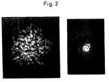
- the reason for this limitation lies in the statistical "speckle structure" of the light spot image, as shown in FIG. 2. Speckle noise essentially arises - even when illuminated with so-called incoherent sources - because in the elementary act of scattering, every excited atom emits light whose phase is correlated with that of the exciting light, whereby the exciting and the scattered light are capable of interference or 'coherent' with each other. This is also the case with the scattering of sunlight on objects, as is the case with the known distance sensors.
- the coherence function becomes wider when light is propagated, even the light of an incandescent lamp at the location of an illuminated object surface is not completely spatially incoherent, ie closely adjacent surface elements are illuminated in a phase-correlated manner. In the case of coherent scattering, the reflected light from two adjacent surface points is practically always capable of interference.
- the structure shown in FIG. 2 is determined by the respective microtopography of the object surface and has the consequence that the respective light spot image can only be detected with statistical uncertainty, which also impairs the accuracy of the distance determination.
- ⁇ x means the statistical uncertainty (standard deviation) of the lateral localization of the light spot, ⁇ the wavelength and sin u the observation aperture.
- ⁇ z means the measurement uncertainty (standard deviation) of the lateral localization of the light spot, ⁇ the wavelength and sin u the observation aperture.
- the measurement uncertainty based on speckle is calculated according to equation (3): ⁇ z ⁇ ⁇ / sin2u (3), which corresponds to the classic depth of field according to Rayleigh.
- the sensor therefore shows a very good range resolution. However, this only applies to object shifts that are small compared to the depth of field of the observation, since only then will the speckle structure be preserved.
- the sensor should display the same distance regardless of the movement. However, this is not the case.
- the sensor signal simulates the presence of a "mountainous" surface, as shown in FIG. 3, with a standard deviation of the height, which is given by equations (2) and (3).
- This standard deviation ⁇ z is not the surface roughness of the object surface, as is sometimes claimed. ⁇ z has nothing at all to do with the microtopography of the surface, but is determined exclusively by an apparatus property, the observation aperture, and can be a multiple of the object roughness.
- the radiation used to measure the distance encoding should be largely spatially incoherent.
- a (small) incoherent point source e.g. B. depicts a high-pressure mercury sheet on the object.
- the width of the spatial coherence function on the object is equal to the width of the diffraction image (point image) of the illuminating optics (M. Born, E. Wolf, “Prinziples of optics", Pergamonn Press, New York, 1970) .
- point image the diffraction image of the illuminating optics
- the above-described impairment of a highly accurate distance determination by the "speckle structure" The light spot images obtained also exist in a measuring device known from DE-A-33 42 675 for the optical scanning of workpieces according to the triangulation principle.
- a light spot is projected from one or two projectors at an angle onto the surface of the measurement object and the shift in the light spot image that occurs when the distance to the object changes is determined with a light-sensitive detector.
- the shape and the area of the light spot are also measured by means of image analysis.
- the coherent radiation of the illuminated light spot is evaluated, the measurement inaccuracies caused by the speckle structure of the light spot image also result here.
- the object of the invention is to provide a method and a device for determining the distance, in which the limitations of the prior art are eliminated and with which highly precise measurement results can be obtained with technically simple means.
- the object itself is excited by the electromagnetic radiation in a locally limited area to emit radiation which is not coherent with the exciting radiation. It is also the radiation of closely spaced atoms on the object surface does not correlate, ie the excited light spot radiates spatially and generally incoherently. Since, furthermore, according to the invention only this incoherent radiation emitted by the light spot is evaluated for the distance determination, no speckle structure occurs in the light spot image, which enables a more precise position determination of the light spot image and thus also a much more precise distance determination.
- An advantageous embodiment is characterized in that the object in the light spot from the radiation source, for. B. a laser, locally heated so much that it emits thermal (Planckian) radiation. This is spatially and temporally incoherent. Another possibility is the excitation of luminescence, which is composed of fluorescence and phosphorescence. Raman scattering as well as Brillouin scattering or other incoherent scattering mechanisms are also possible.
- a suitable small light source 10 generates a light spot 2 in or on the object 11.
- the light source 10 can be a thermal source, such as an incandescent lamp, a gas discharge lamp, a light-emitting diode, a gas or semiconductor laser and a superluminescent diode. It is essential that the radiation 13 of the light source 10 is suitable for exciting the surface of the object in the light spot 2 to incoherent radiation 14. Many organic materials show e.g. B. luminescence (fluorescence and phosphorescence) or Raman scattering or Brillouin scattering if they are excited with the correct wavelength. If the object does not emit incoherent radiation, the surface can be activated by suitable treatment, e.g. B. by coating with suitable phosphors 12. Often, small organic surface impurities are sufficient to excite the surface to incoherent emission.
- the hot focal spot generated by the laser beam in or on the object emits the incoherent radiation required for determining the distance.
- Local heating of the object surface which is sufficiently high to emit incoherent radiation, also occurs in other methods of material processing, such as arc welding.
- the spatially incoherent radiation emitted by the object 11 14 is collected in a measuring head 15 and evaluated in order to determine the distance to the object.
- the coherent portion 13a of the radiation 13 also emitted by the object 11 is separated from the emitted incoherent radiation portion 14 before the evaluation. This separation is possible using an optical color filter 16 because the incoherent radiation is usually in a different wavelength range than the coherent radiation.
- Another possibility is to choose the spectral sensitivity of the photoreceiver so that the coherent radiation component 13a is not detected.
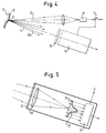
- Another possibility is to interrupt the exciting radiation 13 after a certain time and to carry out the evaluation of the incoherent radiation 14 only after this. This possibility is symbolically represented in FIG. 4 by a switch 17, controlled by the measuring head 15, in front of the light source 10. Since the incoherent excited radiation can also be transmitted with a delay, depending on the choice of the excited material, the incoherent radiation can be evaluated within a time window, the start and end of which can advantageously be set.
- a triangulation measuring head is shown as an example, which contains an imaging line 18 and a locally resolving photo receiver, preferably a 'position-sensitive photodiode' (PSD) or a CCD photodiode array 19 shown in FIG. 5. 5, the individual diodes of such an array 19 are indicated.
- PSD 'position-sensitive photodiode'
- CCD photodiode array 19 shown in FIG. 5. 5
- the individual diodes of such an array 19 are indicated.
- the location of the spot image, its intensity distribution is reproduced as an example at item 20, encodes the distance to the object 11.
- the location of the light spot image can now be determined with extreme accuracy because the shape of the light spot image is not statistically disturbed by speckle.
- the position of the light spot image can also be determined much more precisely than its diameter or also much more precisely than given by the distance between the CCD photodiodes.
- the evaluation can take place in such a way that the three or five highest photodiode signals are used to fit a Gaussian curve or other suitable curve into the measured values.
- the location of the maximum of the fitted curve is a measure of the position of the light spot image. The possible accuracy is now essentially only influenced by the noise of the photo receiver.
- the independence of the distance measurement from possible shape variations of the light spot image is solved according to the invention by the following method, such as. B. shown in Fig. 7.
- the location of the light spot image itself is not determined according to FIG. 7, but at least two shape-matched light spot images 25 and 26 are generated and the distance s between these two shape-matched light spot images Images 25, 26 are measured. It is thus possible to find the distance s between characteristic homologous points x 1, x 1 'or x 2, x 2', etc. in these images, as indicated in FIG. 7. Out the exact position of the homologous points, as can be determined in an evaluation unit 27, the distance s and thus the object distance can be evaluated.
- the homologous points can e.g. B. local maxima or minima. But you can also determine the center of gravity of the light spot image and determine the distance of the center of gravity of the different light spot images in order to determine the object distance from it.
- a correlation of the light spot images 25, 26 can also be carried out and the distance s can be calculated therefrom in a known manner.
- FIGS. 8 to 10 Two versions of such a measuring device are shown in FIGS. 8 to 10.
- the radiation 13 generated in the light source 2 is reflected at a splitter mirror 28 towards the object 11.
- the incoherent radiation 14 re-emitted in the light spot 2 passes through the color filter 16 and a converging lens 30.
- Behind this converging lens 30 there is a diaphragm 32 having a plurality of spaced openings, which in the embodiment according to FIG. 8 is designed as a double slit diaphragm. Apertures with several different openings are also possible.
- the distance s of the blurred light spot images depends on the distance z of the light spot 2 from the lens 30.
- the change in distance ⁇ s of the unsharp luminous spot images 25, 26 can be calculated as follows.
- ⁇ ⁇ 1.
- the unsharp luminous spot images 25, 26 are not mirror-symmetrical to the optical axis, but each have the same orientation as shown in FIG. 8, so that the distance between homologous points becomes independent of the shape .
- the unsharp luminous spot images 25, 26 also appear as an unsharp projection of the pupil, they are slit-shaped in the example above. This is somewhat disadvantageous since the photodetector should then take up such a large area that all of the light is captured.
- the use of a photodiode array, which is used in conjunction with a cylinder converging lens 33 shown in FIG. 8, is cheaper and better for faster evaluation.
- This cylinder converging lens 33 is oriented in such a way that the unsharp slit projections are drawn together approximately at one point, as shown in FIG. 9. This enables the use of a line-shaped photo receiver instead of a flat photo receiver without losses.
- a further embodiment for generating two or more identical light spot images, the mutual distance of which depends on the object distance, results from the use of a birefringent element through which the light of the light spot passes.
- a birefringent element through which the light of the light spot passes.
- Incoherent radiation generated in the light spot 2 for example by a Savart plate 36, with an upstream polarizer 37 and a downstream polarizer 38.
- This arrangement generates two virtual double images of the light spot at points 39 and 40, at a distance p, through the Savart plate 36 is given.
- the light from these double images comes to interference in a plane 41 behind the Savart plate. Interference fringes 42 can be observed there.
- the distance l of the interference fringes is determined and the object distance is derived from them.
Abstract
Description
Die Erfindung betrifft ein Verfahren und eine Vorrichtung zur Abstandsmessung der im jeweiligen Oberbegriff der Patentansprüche 1 (Verfahren) bzw. 9 (Vorrichtung) angegebenen Gattung.The invention relates to a method and a device for measuring the distance of the type specified in the respective preamble of claims 1 (method) and 9 (device).
Zur genauen Messung von Abständen zwischen einem Objekt, z. B. der Oberfläche eines eingespannten Werkstücks, und einem Bezugspunkt sind verschiedene Meßprinzipien bekannt, die sich gliedern lassen in Interferometrie, Laufzeitmethoden, Fokussuche und Triangulation (vgl. T. C. Strand, "Optical three-dimensional sensing for machine vision", Opt. Eng. 24, 33 (1985)). Da Interferometrie für optisch diffus streuende Oberflächen, wie sie im Maschinenbau vorkommen, nicht geeignet ist und Laufzeitmessungen zu ungenau sind, basieren die meisten kommerziell eingesetzten Abstandssensoren auf der Triangulation oder der Fokussuche. Diese beiden Methoden sind physikalisch ähnlich und unterliegen auch den gleichen physikalischen Beschränkungen.For the precise measurement of distances between an object, e.g. B. the surface of a clamped workpiece, and a reference point, various measuring principles are known, which can be divided into interferometry, runtime methods, focus search and triangulation (cf. TC Strand, "Optical three-dimensional sensing for machine vision", Opt. Eng. 24 , 33 (1985)). Since interferometry is not suitable for optically diffusely scattering surfaces, as they occur in mechanical engineering, and runtime measurements are too imprecise, most commercially used distance sensors are based on triangulation or focus search. These two methods are physically similar and are also subject to the same physical restrictions.
Der am meisten verbreitete Abstandssensor basiert auf dem in Fig. 1 schematisch dargestellten Prinzip. Danach wird ein Leuchtfleck 2 als Bild einer Lichtquelle 1 in Richtung der Beleuchtungsachse 3 auf ein Objekt 4 projiziert. Das an der Objektoberfläche reflektierte kohärente Licht wird in einem Meßkopf 5 in Richtung der Beobachtungsachse 6, die unter einem Triangulationswinkel ϑ gegen die Beleuchtungsachse geneigt ist, in einem Leuchtfleck-Bild 7 auf einem Photoempfänger 8 gesammelt. Der Meßabstand wird durch Triangulation bestimmt. Dabei bewirkt eine Abstandsänderung der Objektoberfläche mit dem Leuchtfleck 2 um eine Strecke Δz eine meßbare laterale Verschiebung Δx des Leuchtfleck-Bildes 7 zur Position 9.The most widespread distance sensor is based on the principle shown schematically in FIG. 1. A
Die Genauigkeit der Abstandsbestimmung wird durch die Genauigkeit der positionsbestimmung des Leuchtfleck-Bildes 7 bzw. 9 gegeben, die jedoch durch physikalische Grenzen fundamental beschränkt ist. Die Ursache für diese Begrenzung liegt in der statistischen "Speckle-Struktur" des Leuchtfleck-Bildes, wie es in Fig. 2 dargestellt ist. Specklerauschen entsteht im wesentlichen - auch bei Beleuchtung mit sogenannt inkohärenten Quellen -, weil beim elementaren Streuungsakt jedes angeregte Atom Licht emittiert, dessen Phase mit der des anregenden Lichtes korreliert ist, wobei das anregende und das gestreute Licht interferenzfähig oder 'zueinander kohärent' sind. Dies ist auch der Fall bei der Streuung von Sonnenlicht an Gegenständen, ebenso wie bei den bekannten Abstandssensoren. Weil die Kohärenzfunktion bei der Ausbreitung von Licht breiter wird, ist selbst das Licht einer Glühlampe am Ort einer beleuchteten Objektoberfläche nicht vollständig räumlich inkohärent, d. h., eng benachbarte Oberflächenelemente werden phasenkorreliert beleuchtet. Bei kohärenter Streuung ist praktisch immer das remittierte Licht zweier benachbarter Oberflächenpunkte interferenzfähig.The accuracy of the distance determination is given by the accuracy of the position determination of the
Die in Fig. 2 dargestellte Struktur wird durch die jeweilige Mikrotopografie der Objektoberfläche bestimmt und hat zur Folge, daß das jeweilige Leuchtfleck-Bild nur mit einer statistischen Unsicherheit erfaßt werden kann, was auch die Genauigkeit der Abstandsbestimmung beeinträchtigt. Diese Zusammenhänge und mögliche Auswege sind u. a. in den DE-A-36 14 332, Wo 89/11 630 und DE-A-37 031 882 im einzelnen beschrieben.The structure shown in FIG. 2 is determined by the respective microtopography of the object surface and has the consequence that the respective light spot image can only be detected with statistical uncertainty, which also impairs the accuracy of the distance determination. These relationships and possible ways out are u. a. in DE-A-36 14 332, where 89/11 630 and DE-A-37 031 882 described in detail.
Ferner ist bekannt (G. Häusler, "About fundamental limits of three-dimensional sensing", 15th Congress of the Int. Com. for Optics, Ed. F. Lanzl, 352 (1990)), daß alle Verfahren, die mit kohärentem Licht arbeiten, an die o. g. physikalische Grenze der Genauigkeit stoßen, die durch die Wechselwirkung von kohärentem Licht mit den im Maschinenbau üblichen rauhen Oberflächen bewirkt wird. Die am Objekt gestreute Welle weist eine räumlich variierende Phasen- und Intensitätsfluktuation auf, die eine Lokalisation des Streuflecks über eine bestimmte Genauigkeitsgrenze hinaus verhindert. Diese Genauigkeitsgrenze ist im wesentlichen durch die Beobachtungsapertur gegeben:
![]()
It is also known (G. Häusler, "About fundamental limits of three-dimensional sensing", 15th Congress of the Int. Com. For Optics, Ed. F. Lanzl, 352 (1990)) that all methods using coherent light work, reach the physical limit of accuracy mentioned above, which is caused by the interaction of coherent light with the rough surfaces common in mechanical engineering. The wave scattered on the object exhibits a spatially varying phase and intensity fluctuation, which prevents the scatter spot from being localized beyond a certain accuracy limit. This accuracy limit is essentially given by the observation aperture:
![]()
Dabei bedeuten δx die statistische Unsicherheit (Standardabweichung) der lateralen Lokalisation des Leuchtflecks, λ die Wellenlänge und sin u die Beobachtungsapertur. Bei Triangulationsmessungen, zwischen denen ein Triangulationswinkel ϑ zwischen der Achse der Strahlung und der Achse der Beobachtung benutzt wird, führt die laterale Lokalisationsunsicherheit zu einer Meßunsicherheit δ z bezüglich der Entfernung:
![]()
Here δx means the statistical uncertainty (standard deviation) of the lateral localization of the light spot, λ the wavelength and sin u the observation aperture. In triangulation measurements, between which a triangulation angle ϑ between the axis of the radiation and the axis of the observation is used, the lateral localization uncertainty leads to a measurement uncertainty δ z with respect to the distance:
![]()
Bei Verfahren, die auf Fokussuche beruhen, errechnet sich die Meßunsicherheit aufgrund von Speckle nach Gleichung (3):
![]()
was der klassischen Schärfentiefe nach Rayleigh entspricht.In the case of methods that are based on a focus search, the measurement uncertainty based on speckle is calculated according to equation (3):
![]()
which corresponds to the classic depth of field according to Rayleigh.
Die Gleichungen (2) und (3) sagen im wesentlichen aus, daß mit kohärenter Strahlung für eine geringe Meßunsicherheit δz eine große Beobachtungsapertur sin u notwendig ist und/oder ein großer Triangulationswinkel ϑ. Für eine geforderte Meßunsicherheit unter 10 µm führt dies zu unpraktikablen Winkeln u und ϑ. Beispielsweise wird bei einer Wellenlänge von λ = 0.8 µm für eine Meßgenauigkeit von δz ≈ 10 µm bei Fokussuche eine Apertur von sin u ≈ 0.28 benötigt, also ein Aperturwinkel von fast 30°. Ein solcher Winkel ist für mikroskopische Anwendungen eventuell praktikabel, für makroskopische Dimensionen führt er jedoch zu sehr großen Linsen. Überdies stört die Abschattung der Randstrahlen, d. h. man kann nicht in Löcher hineinsehen.The equations (2) and (3) essentially state that a large observation aperture sin u and / or a large triangulation angle ϑ is necessary for a low measurement uncertainty δz with coherent radiation. For a required measurement uncertainty below 10 µm, this leads to impractical angles u and ϑ. For example, with a wavelength of λ = 0.8 µm, an aperture of sin u ≈ 0.28 is required for a measurement accuracy of δz ≈ 10 µm when searching for focus, i.e. an aperture angle of almost 30 °. Such an angle may be practical for microscopic applications, but for macroscopic dimensions it leads to very large lenses. In addition, the shadowing of the marginal rays, i. H. you cannot look into holes.
Es ist noch wesentlich, zwischen Genauigkeit und Auflösung zu unterscheiden: Richtet man einen oben beschriebenen Sensor auf ein Objekt, so wird der Sensor eine Entfernung anzeigen, die im Rahmen der durch die Gleichungen (2), (3) angegebenen Toleranz genau ist. Verfährt man das Objekt um eine kleine Strecke in Richtung auf den Sensor, so wird die entsprechende Entfernungsänderung angezeigt.It is still important to differentiate between accuracy and resolution: If you point a sensor described above at an object, the sensor will display a distance that is accurate within the tolerance specified by equations (2), (3). If you move the object a short distance towards the sensor, the corresponding change in distance is displayed.
Der Sensor zeigt also eine durchaus gute Entfernungsauflösung. Dies gilt jedoch nur für Objektverschiebungen, die klein gegen die Schärfentiefe der Beobachtung sind, da nur dann die Speckle-Struktur erhalten bleibt.The sensor therefore shows a very good range resolution. However, this only applies to object shifts that are small compared to the depth of field of the observation, since only then will the speckle structure be preserved.
Wenn aber ein Objekt mit einer völlig ebenen (aber rauhen) Objektoberfläche parallel zur Oberflächenebene verschoben wird, sollte der Sensor unabhängig von der Verschiebung die gleiche Entfernung anzeigen. Dies ist jedoch nicht der Fall. Das Sensorsignal täuscht das Vorhandensein einer 'gebirgigen' Oberfläche vor, wie in Fig. 3 wiedergegeben, mit einer Standardabweichung der Höhe, die durch Gleichung (2) bzw. (3) gegeben ist. Diese Standardabweichung δz ist nicht die Rauhtiefe der Objektoberfläche, wie gelegentlich behauptet wird. δz hat überhaupt nichts mit der Mikrotopografie der Oberfläche zu tun, sondern wird ausschließlich durch eine Apparateeigenschaft, die Beobachtungsapertur, bestimmt, und kann ein Vielfaches der Objekt-Rauhtiefe betragen.However, if an object with a completely flat (but rough) object surface is moved parallel to the surface plane, the sensor should display the same distance regardless of the movement. However, this is not the case. The sensor signal simulates the presence of a "mountainous" surface, as shown in FIG. 3, with a standard deviation of the height, which is given by equations (2) and (3). This standard deviation δz is not the surface roughness of the object surface, as is sometimes claimed. δz has nothing at all to do with the microtopography of the surface, but is determined exclusively by an apparatus property, the observation aperture, and can be a multiple of the object roughness.
Um die Speckle-Struktur und damit statistische Meßfehler zu vermeiden, sollte die zur Messung verwendete Strahlung, die die Entfernung codiert, weitgehend räumlich inkohärent sein. Dies läßt sich aber nicht erreichen, indem man eine (kleine) inkohärente Punktquelle, z. B. einen Quecksilber-Höchstdruckbogen auf das Objekt abbildet. Denn nach der Kohärenztheorie ist nach der Abbildung die Breite der räumlichen Kohärenzfunktion auf dem Objekt gleich der Breite des Beugungsbildes (Punktbildes) der beleuchtenden Optik (M. Born, E. Wolf, "Prinziples of optics", Pergamonn Press, New York, 1970). Damit ist das Bild einer auch inkohärenten sehr kleinen Quelle immer räumlich kohärent.In order to avoid the speckle structure and thus statistical measurement errors, the radiation used to measure the distance encoding should be largely spatially incoherent. However, this cannot be achieved by using a (small) incoherent point source, e.g. B. depicts a high-pressure mercury sheet on the object. Because according to the coherence theory, the width of the spatial coherence function on the object is equal to the width of the diffraction image (point image) of the illuminating optics (M. Born, E. Wolf, "Prinziples of optics", Pergamonn Press, New York, 1970) . This means that the image of a very small source, which is also incoherent, is always spatially coherent.
Weitgehende räumliche Inkohärenz im Leuchtfleck 2 ließe sich also nur erreichen, wenn die auf das Objekt abgebildete Strahlungsquelle 1 großflächig ist, so daß auch der Leuchtfleck groß gegenüber dem Punktbild der Projektionsoptik ist. Ein solches Vorgehen hat aber den Nachteil, daß man auf dem Objekt keinen kleinen Punkt mehr durch Beleuchtung adressiert, sondern einen großen Bereich, so daß die laterale Auflösung reduziert wird. Außerdem ist die Lokalisation eines großflächigen Leuchtfleck-Bildes auf dem Photoempfänger nur mit geringerer Genauigkeit möglich. Es wurde auch versucht (vgl. DE-A-36 14 332 und W. Dremel, G. Häusler, M. Maul, "Triangulation with large dynamical range", Optical Techniques for Industrial Inspection, Ed. G. Paolo, Proc. SPIE 665, 182 (1986)), das Objekt mit einem Laser zu beleuchten und den Laser-Leuchtfleck während der Messung über das Objekt zu bewegen. Dies ist äquivalent zur Beleuchtung mit einer großen inkohärenten Lichtquelle und führt zu den gleichen Problemen. Eine andere Möglichkeit ist, durch Erzeugung von Turbulenz in der Pupille der abbildenden Optik den Laser-Leuchtfleck auf dem Objekt statistisch tanzen zu lassen. Auch dies ist äquivalent zu den obigen Methoden und führte nicht zu den verlangten Meßgenauigkeiten im µm-Bereich. Mit anderen Worten, es läßt sich keine genügend räumlich inkohärente Beleuchtung ohne den oben erwähnten Nachteil eines großen Leuchtflecks erzielen. Eine zeitlich inkohärente Beleuchtung wird zur Speckle-Reduktion erst bei sehr großen Rauhtiefen des Objektes wirksam, wie sie praktisch im Maschinenbau nicht vorkommen.Extensive spatial incoherence in the
Die vorstehend beschriebene Beeinträchtigung einer hochgenauen Abstandsbestimmung durch die "Speckle-Struktur" der erhaltenen Leuchtfleckbilder besteht auch bei einer aus der DE-A-33 42 675 bekannten Meßvorrichtung zur optischen Abtastung von Werkstücken nach dem Triangulationsprinzip. Von einem oder auch zwei Projektoren wird ein Lichtfleck unter einem Winkel auf die Oberfläche des Meßobjekts projiziert und mit einem lichtempfindlichen Detektor wird die bei Änderung des Abstands zum Objekt auftretende Verschiebung des Lichtfleck-Bildes bestimmt. Zur Erhöhung der Genauigkeit der Abstandsbestimmung wird zusätzlich zur lateralen Verschiebung des Bildes auch noch die Form und der Flächeninhalt des Lichtflecks mittels Bildanalyse gemessen. Da jedoch die kohärente Strahlung des angestrahlten Lichtflecks ausgewertet wird, ergeben sich auch hier die durch die Speckle-Struktur des Lichtfleck-Bildes erursachten Meßungenauigkeiten.The above-described impairment of a highly accurate distance determination by the "speckle structure" The light spot images obtained also exist in a measuring device known from DE-A-33 42 675 for the optical scanning of workpieces according to the triangulation principle. A light spot is projected from one or two projectors at an angle onto the surface of the measurement object and the shift in the light spot image that occurs when the distance to the object changes is determined with a light-sensitive detector. In order to increase the accuracy of the distance determination, in addition to the lateral displacement of the image, the shape and the area of the light spot are also measured by means of image analysis. However, since the coherent radiation of the illuminated light spot is evaluated, the measurement inaccuracies caused by the speckle structure of the light spot image also result here.
Entsprechendes gilt auch für die aus den DE-A-40 06 300 und US-A-4 453 083 bekannten Abstands-Meßvorrichtungen.The same also applies to the distance measuring devices known from DE-A-40 06 300 and US-A-4 453 083.
Aufgabe der Erfindung ist es, ein Verfahren und eine Vorrichtung zur Abstandsbestimmung aufzuzeigen, bei denen die Beschränkungen des Standes der Technik eliminiert sind und mit denen mit technisch einfachen Mitteln hochgenaue Meßergebnisse erhalten werden können.The object of the invention is to provide a method and a device for determining the distance, in which the limitations of the prior art are eliminated and with which highly precise measurement results can be obtained with technically simple means.
Diese Aufgabe wird durch die in den Patentansprüchen 1 bzw. 9 angegebenen Merkmale gelöst.This object is achieved by the features specified in
Gemäß der Erfindung wird das Objekt selbst durch die elektromagnetische Strahlung in einem lokal begrenzten Bereich zur Emission von Strahlung angeregt, die nicht kohärent zur anregenden Strahlung ist. Dabei ist auch die Strahlung nahe beieinanderliegender Atome auf der Objektoberfläche nicht korreliert, d. h. der angeregte Leuchtfleck strahlt räumlich und im allgemeinen auch zeitlich inkohärent. Da ferner erfindungsgemäß nur diese vom Leuchtfleck emittierte inkohärente Strahlung zur Abstandsbestimmung ausgewertet wird, tritt keine Speckle-Struktur im Leuchtfleck-Bild auf, was eine genauere Positionsbestimmung des Leuchtfleck-Bildes und damit auch eine wesentlich genauere Abstandsbestimmung ermöglicht.According to the invention, the object itself is excited by the electromagnetic radiation in a locally limited area to emit radiation which is not coherent with the exciting radiation. It is also the radiation of closely spaced atoms on the object surface does not correlate, ie the excited light spot radiates spatially and generally incoherently. Since, furthermore, according to the invention only this incoherent radiation emitted by the light spot is evaluated for the distance determination, no speckle structure occurs in the light spot image, which enables a more precise position determination of the light spot image and thus also a much more precise distance determination.
Eine zweckmäßige Ausgestaltung zeichnet sich dadurch aus, daß das Objekt im Leuchtfleck von der Strahlungsquelle, z. B. einem Laser, lokal so stark aufgeheizt wird, daß es thermische (Planck'sche) Strahlung emittiert. Diese ist räumlich und auch zeitlich inkohärent. Eine weitere Möglichkeit ist die Anregung von Lumineszenz, die sich aus Fluoreszenz und Phosphoreszenz zusammensetzt. Ebenfalls in Frage kommen Raman-Streuung sowie Brillouin-Streuung oder andere inkohärente Streumechnismen.An advantageous embodiment is characterized in that the object in the light spot from the radiation source, for. B. a laser, locally heated so much that it emits thermal (Planckian) radiation. This is spatially and temporally incoherent. Another possibility is the excitation of luminescence, which is composed of fluorescence and phosphorescence. Raman scattering as well as Brillouin scattering or other incoherent scattering mechanisms are also possible.
Mit einem auf dem Objekt erzeugten Leuchtfleck, der diese Art von Strahlung emittiert, gibt es keine statistische Meßunsicherheit mehr durch Speckle, so daß die durch die Gleichungen (2) und (3) gegebene Grenze der Meßunsicherheit um Größenordnungen unterschritten wird.With a light spot generated on the object and emitting this type of radiation, there is no longer any statistical measurement uncertainty due to speckle, so that the limit of the measurement uncertainty given by equations (2) and (3) is below orders of magnitude.
In den Unteransprüchen sind vorteilhafte Weiterbildungen und Varianten der Erfindung angegeben.Advantageous further developments and variants of the invention are specified in the subclaims.
Weitere Besonderheiten und Vorzüge der Erfindung lassen sich der folgenden Beschreibung von Ausführungsbeispielen anhand der Zeichnung entnehmen. Es zeigen:
- Fig. 1
- das - bekannte - Prinzip der Abstandsmessung durch aktive Triangulation;
- Fig. 2
- ein durch Speckle-Struktur gestörtes Leuchtfleckbild für zwei verschiedene Beobachtungsaperturen, das bei dem Meßverfahren nach Fig. 1 erhalten wird;
- Fig. 3
- ein Diagramm der durch Speckle vorgetäuschten Unebenheit einer ebenen Fläche;
- Fig. 4
- das Prinzip der Abstandsmessung gemäß der Erfindung;
- Fig. 5
- einen Triangulationsmeßkopf in schematischer Darstellung;
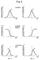
- Fig. 6
- durch Veränderung der Form des Leuchtfleckbildes entstehende Meßfehler in Form von Diagrammen;
- Fig. 7
- unabhängig von der Form des Leuchtflecks eine Möglichkeit zur Kompensation der auf Formänderungen des Leuchtfleckbildes zurückgehenden Meßfehler;
- Fig. 8
- eine Meßanordnung für eine von der Leuchtfleckform unabhängige Abstandsmessung;
- Fig. 9
- eine Meßanordnung mit Doppelschlitzblende und einer Zylinderlinse für die inkohärente Meßstrahlung;
- Fig. 10
- eine Meßanordnung mit virtueller Leuchtfleckverdopplung durch eine Savartplatte.
- Fig. 1
- the - known - principle of distance measurement through active triangulation;
- Fig. 2
- a light spot image disturbed by speckle structure for two different observation apertures, which is obtained in the measuring method according to FIG. 1;
- Fig. 3
- a diagram of the unevenness of a flat surface simulated by speckle;
- Fig. 4
- the principle of distance measurement according to the invention;
- Fig. 5
- a triangulation measuring head in a schematic representation;
- Fig. 6
- measurement errors resulting from changing the shape of the light spot image in the form of diagrams;
- Fig. 7
- independent of the shape of the light spot, a possibility to compensate for measurement errors due to changes in shape of the light spot image;
- Fig. 8
- a measuring arrangement for a distance measurement independent of the shape of the spot;
- Fig. 9
- a measuring arrangement with a double slit diaphragm and a cylindrical lens for the incoherent measuring radiation;
- Fig. 10
- a measuring arrangement with virtual doubling of the light spot by a Savart plate.
Wie in Fig. 4 gezeigt, wird durch eine geeignete kleine Lichtquelle 10 in bzw. auf dem Objekt 11 ein Leuchtfleck 2 erzeugt. Die Lichtquelle 10 kann eine thermische Quelle sein, wie eine Glühlampe, eine Gasentladungslampe, eine Leuchtdiode, ein Gas- oder Halbleiterlaser sowie eine Superlumineszenzdiode. Wesentlich ist dabei, daß die Strahlung 13 der Lichtquelle 10 geeignet ist, die Oberfläche des Objektes im Leuchtfleck 2 zu inkohärenter Strahlung 14 anzuregen. Viele organische Materialien zeigen z. B. Lumineszenz (Fluoreszenz und Phosphoreszenz) oder Raman-Streuung oder Brillouin-Streuung, wenn sie mit der richtigen Wellenlänge angeregt werden. Falls das Objekt keine inkohärente Strahlung emittiert, kann man die Oberfläche durch geeignete Behandlung aktivieren, z. B. durch Beschichten mit geeigneten Phosphoren 12. Oft genügen geringe organische Oberflächenverunreinigungen, um die Oberfläche zu inkohärenter Emission anzuregen.As shown in FIG. 4, a suitable small light source 10 generates a
Wenn das erfindungsgemäße Meßverfahren bei der abtragenden Bearbeitung eines Werkstücks mittels Laserstrahls eingesetzt wird, emittiert der vom Laserstrahl im bzw. auf dem Objekt erzeugte heiße Brennfleck die zur Abstandsbestimmung benötigte inkohärente Strahlung. Auch bei anderen Verfahren der Materialbearbeitung, wie dem Lichtbogenschweißen, tritt eine zur Emission von inkohärenter Strahlung ausreichend hohe lokale Aufheizung der Objektoberfläche auf.If the measuring method according to the invention is used in the machining of a workpiece by means of a laser beam, the hot focal spot generated by the laser beam in or on the object emits the incoherent radiation required for determining the distance. Local heating of the object surface, which is sufficiently high to emit incoherent radiation, also occurs in other methods of material processing, such as arc welding.
Die vom Objekt 11 emittierte räumlich inkohärente Strahlung 14 wird in einem Meßkopf 15 aufgefangen und ausgewertet, um den Abstand zum Objekt zu bestimmen. Dabei wird der vom Objekt 11 ebenfalls emittierte kohärente Anteil 13a der Strahlung 13 vom emittierten inkohärenten Strahlungsanteil 14 vor der Auswertung getrennt. Diese Trennung ist durch ein optisches Farbfilter 16 möglich, weil die inkohärente Strahlung meist in einem anderen Wellenlängenbereich als die kohärente Strahlung liegt. Eine andere Möglichkeit besteht darin, die spektrale Empfindlichkeit des Photoempfängers so zu wählen, daß der kohärente Strahlungsanteil 13a nicht erfaßt wird. Eine weitere Möglichkeit besteht darin, die anregende Strahlung 13 nach einer gewissen Zeit zu unterbrechen und die Auswertung der inkohärenten Strahlung 14 erst danach vorzunehmen. Diese Möglichkeit ist in Fig. 4 symbolisch durch einen vom Meßkopf 15 gesteuerten Schalter 17 vor der Lichtquelle 10 dargestellt. Da die inkohärente angeregte Strahlung auch verzögert ausgesendet werden kann, je nach Wahl des angeregten Materials, kann die inkohärente Strahlung innerhalb eines Zeitfensters, dessen Beginn und Ende vorteilhaft einstellbar sind, ausgewertet werden.The spatially incoherent radiation emitted by the object 11 14 is collected in a measuring
Es sind verschiedene Ausführungen des Meßkopfes 15 möglich, weil die Entfernungsinformation, die im emittierten Licht steckt, auf verschiedene Weise decodiert werden kann. In den Fig. 4 und 5 ist ein Triangulations-Meßkopf als Beispiel dargestellt, der eine Abbildungslinie 18 und einen örtlich auf lösenden Photoempfänger, vorzugsweise eine 'positionsempfindliche Photodiode' (PSD) oder ein in Fig. 5 dargestelltes CCD-Photodiodenarray 19, enthält. In Fig. 5 sind die einzelnen Dioden eines solchen Arrays 19 angegeben. Der Ort des Leuchtfleck-Bildes, dessen Intensitätsverteilung bei Pos 20 beispielhaft wiedergegeben ist, codiert den Abstand zum Objekt 11. Erfindungsgemäß kann der Ort des Leuchtfleck-Bildes nun mit extremer Genauigkeit bestimmt werden, weil die Form des Leuchtfleck-Bildes nicht durch Speckle statistisch gestört ist.Different versions of the measuring
Deshalb kann man die Position des Leuchtfleck-Bildes auch wesentlich genauer bestimmen als seinen Durchmesser oder auch wesentlich genauer als durch den Abstand der CCD-Photodioden gegeben. Man kann in der Auswerteeinheit 21 z. B. den Schwerpunkt des Leuchtfleck-Bildes bestimmen oder den Ort der maximalen Intensität, d. h. den Scheitelpunkt der Verteilungskurve 21, wobei sich diese Größen durch Subpixel-Interpolation oft genauer als auf 1 µm in der Ebene des Photoempfängers bestimmen lassen. Die Auswertung kann in diesem Fall so erfolgen, daß die drei oder fünf höchsten Photodiodensignale benutzt werden, um eine Gausskurve oder andere passende Kurve in die Meßwerte hineinzufitten. Die Lage des Maximums der gefitteten Kurve ist ein Maß für die Position des Leuchtfleck-Bildes. Die mögliche Genauigkeit wird jetzt nur noch im wesentlichen durch das Rauschen des Photoempfängers beeinflußt.Therefore, the position of the light spot image can also be determined much more precisely than its diameter or also much more precisely than given by the distance between the CCD photodiodes. One can in the evaluation unit 21 z. B. determine the focus of the spot image or the location of maximum intensity, d. H. the vertex of the
Es sind viele weitere Varianten und Ausgestaltungen des Meßkopfes denkbar, von denen noch zwei Ausführungen gezeigt werden, die weitere besondere Vorteile bieten.Many other variants and configurations of the measuring head are conceivable, of which two versions are shown which offer further special advantages.
Verfahren, die die Position eines Leuchtfleck-Bildes auswerten, sind darauf angewiesen, daß die Form dieses Leuchtfleck-Bildes unabhängig vom adressierten Ort auf dem Objekt ist und unabhängig von der Entfernung. Dies wird deutlich durch Fig. 6: Wenn das Objekt z. B. eine örtliche Änderung der Reflexion oder Emissionsfähigkeit R(x) aufweist, so sieht das Leuchtfleck-Bild für den Ort A anders aus, als für den Ort B. Eine Bestimmung des Schwerpunktes würde zu geringfügigen Meßfehlern führen.Methods that evaluate the position of a light spot image are dependent on the shape of this light spot image being independent of the addressed location on the object and independent of the distance. This becomes clear through Fig. 6: If the object z. B. shows a local change in the reflection or emissivity R (x), the light spot image looks different for location A than for location B. A determination of the center of gravity would lead to minor measurement errors.
Eine solche lokale Variation der Form des Leuchtfleck-Bildes, je nach dem adressierten Ort auf der Objektoberfläche, kann man aber nicht ausschließen. Es kann nicht nur lokale Variation der Reflexion oder Emissionsfähigkeit vorliegen, es kann z. B. auch der Leuchtfleck selbst durch Turbulenz zeitlich und örtlich variieren. Zwar wird der Effekt i. a. klein sein, wenn der Leuchtfleck klein ist, aber wegen der unterdrückten Speckle und der damit erreichbaren hohen Genauigkeit soll auch ein Einfluß der Form des Leuchtflecks auf das Meßergebnis ausgeschlossen werden. Da bei den bekannten Verfahren das Speckle die Hauptfehlerquelle ist, war es bisher nicht notwendig, diesem Effekt Beachtung zu schenken.Such a local variation of the shape of the light spot image, depending on the addressed location on the object surface, cannot be ruled out. Not only can there be local variation in reflection or emissivity; B. the light spot itself may vary in time and location due to turbulence. The effect i. a. be small if the light spot is small, but because of the suppressed speckle and the high accuracy that can be achieved with it, an influence of the shape of the light spot on the measurement result should also be excluded. Since speckle is the main source of error in the known methods, it has not previously been necessary to pay attention to this effect.
Die Unabhängigkeit der Abstandsmessung von eventuellen Formvariationen des Leuchtfleck-Bildes wird erfindungsgemäß durch folgendes Verfahren gelöst, wie z. B. in Fig. 7 dargestellt. Um den Einfluß der Form des Leuchtfleck-Bildes zu beseitigen, wird gemäß Fig. 7 nicht der Ort des Leuchtfleck-Bildes selbst bestimmt, sondern es werden mindestens zwei formgleiche Leuchtfleck-Bilder 25 und 26 erzeugt und die Entfernung s zwischen diesen beiden formgleichen Leuchtfleck-Bildern 25, 26 wird gemessen. Damit ist es möglich, in diesen Bildern jeweils die Entfernung s zwischen charakteristischen homologen Punkten x₁, x₁' bzw. x₂, x₂', etc. zu finden, wie in Fig. 7 angegeben. Aus der genauen Lage der homologen Punkte, wie in einer Auswerteeinheit 27 bestimmt werden kann, läßt sich der Abstand s und damit die Objektentfernung auswerten.The independence of the distance measurement from possible shape variations of the light spot image is solved according to the invention by the following method, such as. B. shown in Fig. 7. In order to eliminate the influence of the shape of the light spot image, the location of the light spot image itself is not determined according to FIG. 7, but at least two shape-matched
Die homologen Punkte können z. B. lokale Maxima oder Minima sein. Man kann aber auch den Schwerpunkt des Leuchtfleck-Bildes bestimmen und die Entfernung der Schwerpunkte der verschiedenen Leuchtfleck-Bilder bestimmen, um daraus den Objektabstand zu ermitteln. Ebenso läßt sich eine Korrelation der Leuchtfleck-Bilder 25, 26 durchführen und daraus auf bekannte Weise der Abstand s errechnen.The homologous points can e.g. B. local maxima or minima. But you can also determine the center of gravity of the light spot image and determine the distance of the center of gravity of the different light spot images in order to determine the object distance from it. A correlation of the
Diese Überlegungen gelten jedoch nicht für Formänderungen des Leuchtfleck-Bildes, die durch Kohärenzeffekte entstehen.However, these considerations do not apply to changes in the shape of the luminous spot image caused by coherence effects.
Die Grundüberlegung, Unabhängigkeit der Abstandsmessung von der Leuchtfleckform zu gewinnen, indem nicht mehr eine Position, sondern die Differenz von mehreren Positionen bestimmt wird, kann auf verschiedene Weise realisiert werden. Zwei Ausführungen einer solchen Meßvorrichtung sind in den Fig. 8 bis 10 dargestellt.The basic idea of gaining independence of the distance measurement from the shape of the light spot by determining the difference between several positions rather than one position can be realized in different ways. Two versions of such a measuring device are shown in FIGS. 8 to 10.
Bei der Ausführung nach Fig. 8 wird die in der Lichtquelle 2 erzeugte Strahlung 13 an einem Teilerspiegel 28 zum Objekt 11 hin reflektiert. Die im Leuchtfleck 2 reemittierte inkohärente Strahlung 14 durchläuft das Farbfilter 16 und eine Sammellinse 30. Hinter dieser Sammellinse 30 ist eine mehrere beabstandete Öffnungen aufweisende Blende 32 angeordnet, die bei der Ausführung nach Fig. 8 als Doppelspaltblende ausgebildet ist. Es sind auch Blenden mit mehreren andersartigen Öffnungen möglich. Der Photodetektor 19 ist hier im Unterschied zur Vorrichtung nach Fig. 5 außerhalb der Brennpunktebene 31 der Sammellinse 18 positioniert. Dadurch entstehen zwei unscharfe, nebeneinanderliegende Leuchtfleck-Bilder 25 und 26 in einem Abstand s. Anders ausgedrückt, erhält man eine unscharfe Projektion der Blende. Der Abstand s der unscharfen Leuchtfleck-Bilder hängt von der Entfernung z des Leuchtflecks 2 von der Linse 30 ab. Die Abstandsänderung Δs der unscharfen Leuchtfleck-Bilder 25, 26 kann wie folgt berechnet werden.In the embodiment according to FIG. 8, the
Es gelten folgende Symbole:
- s
- Abstand der unscharfen Spotbilder;
- Δs
- Abstandsänderung der Leuchtfleck-Bilder;
- z
Entfernung des Leuchtflecks 2 von der Linse 30 (Gegenstandsweite);- b
- Entfernung des Bildes von der Linse (Bildweite);
- D
- Abstand der Spaltblenden in der Pupille;
- A
- Abstand der Detektorebene zur Linse;
- a
- Defokussierung (intrafokal), Abstand Detektorebene;
- β
- Abbildungsmaßstab, β = b/z;
- f
- Brennweite der Linse.
- s
- Distance of the blurred spot images;
- Δs
- Change in distance of the light spot images;
- e.g.
- Distance of the
light spot 2 from the lens 30 (object distance); - b
- Distance of the image from the lens (image width);
- D
- Distance of the slit diaphragms in the pupil;
- A
- Distance of the detector plane to the lens;
- a
- Defocusing (intrafocal), distance detector plane;
- β
- Magnification, β = b / z;
- f
- Focal length of the lens.
Damit läßt sich folgende Gleichung ansetzen
![]()
durch Einsetzen von a = b-A und b = z · β erhält man:
![]()
The following equation can thus be used
![]()
by inserting a = bA and b = z · β one obtains:
![]()
Diese Gleichung wird nach z differenziert:
Weiterhin gilt folgende Abbildungsgleichung
![]()
This equation is differentiated according to z:
The following mapping equation also applies
![]()
Für b wird -z · β eingesetzt und dann nach z aufgelöst; es ergibt sich:
![]()
For b -z · β is used and then resolved to z; the result is:
![]()
Einsetzen in Gleichung (3) liefert nach einigen Umformungen: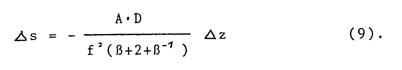
Diese relative Abstandsänderung, die ein Maß für die Empfindlichkeit des Verfahrens ist, hat ihr Optimum bei einem Abbildungsmaßstab von β = -1. Dies kann aus Gleichung (6) gezeigt werden. Die Abstandsänderung Δs wird umso größer, je kleiner der Nenner ist. Es ist also zu untersuchen, wann ![]()
![]()
This relative change in distance, which is a measure of the sensitivity of the method, has its optimum at an imaging scale of β = -1. This can be shown from equation (6). The smaller the denominator, the greater the change in distance Δs. So it has to be examined when ![]()
![]()
Die Nullstellen liegen bei β₀ = ± 1. β = -1 ist physikalisch relevant. Da γ'' (-1) größer als 0 ist, wird für β = -1 tatsächlich γ minimal, d. h. Δs wird maximal. Dies wird erfindungsgemäß ausgenutzt.The zeros are β₀ = ± 1. β = -1 is physical relevant. Since γ '' (-1) is greater than 0, γ actually becomes minimal for β = -1, ie Δs becomes maximum. This is used according to the invention.
Eine weitere äußerst wichtige Eigenschaft der Anordnung ist, daß die unscharfen Leuchtfleck-Bilder 25, 26 nicht spiegelsymmetrisch zur optischen Achse sind, sondern jeweils die gleiche Orientierung haben, wie in Fig. 8 gezeigt, so daß der Abstand homologer Punkte unabhängig von der Form wird.Another extremely important property of the arrangement is that the unsharp
Da die unscharfen Leuchtfleck-Bilder 25, 26 auch als unscharfe Projektion der Pupille erscheinen, sind sie im obigen Beispiel spaltförmig. Dies ist von gewissem Nachteil, da der Photodetektor dann eine so große Fläche einnehmen sollte, daß das gesamte Licht aufgefangen wird. Kostengünstiger und besser für schnellere Auswertung ist die Verwendung einer Photodiodenzeile, die in Verbindung mit einer in Fig. 8 dargestellten Zylinder-Sammellinse 33 eingesetzt wird. Diese Zylinder-Sammellinse 33 ist so orientiert, daß die unscharfen Spaltprojektionen annähernd zu je einem Punkt zusammengezogen werden, wie in Fig. 9 dargestellt. Damit ist die Verwendung eines zeilenförmigen Photoempfängers, anstelle eines flächenhaften Photoempfängers ohne Verluste möglich.Since the unsharp
Eine weitere Ausgestaltung zum Erzeugen von zwei oder mehr formgleichen Leuchtfleck-Bildern, deren gegenseitiger Abstand vom Objektabstand abhängt, entsteht durch die Verwendung eines doppelbrechenden Elementes, durch das das Licht des Leuchtflecks hindurchtritt. Bei einer solchen in Fig. 10 dargestellten Meßvorrichtung tritt die im Leuchtfleck 2 erzeugte inkohärente Strahlung beispielsweise durch eine Savart-Platte 36, mit einem vorgeschalteten Polarisator 37 und einem nachgeschalteten Polarisator 38. Diese Anordnung erzeugt zwei virtuelle Doppelbilder des Leuchtflecks an den Stellen 39 und 40, im Abstand p, der durch die Savart-Platte 36 gegeben ist. Das Licht dieser Doppelbilder kommt in einer Ebene 41 hinter der Savart-Platte zur Interferenz. Es sind dort Interferenzstreifen 42 zu beobachten. Der Abstand ℓ der Interferenzstreifen hängt nach der Beziehung ![]()
![]()
Dadurch kann eine geringe Beobachtungsapertur gewählt werden. Es tritt keine Asymmetrie, wie bei der gewöhnlichen Triangulation mehr auf, die Beleuchtungsrichtung ist gleich der Beobachtungsrichtung. Es gibt nur sehr geringe Abschattung.As a result, a small observation aperture can be selected. Asymmetry no longer occurs, as with ordinary triangulation, the direction of illumination is the same as the direction of observation. There is very little shading.
Claims (17)
dadurch gekennzeichnet,
daß das Objektmaterial im Leuchtfleck durch die elektromagnetische Strahlung erhitzt und zur Emission von räumlich inkohärenter thermischer Strahlung angeregt wird.Method according to claim 1,
characterized,
that the object material in the light spot by the electromagnetic Radiation is heated and excited to emit spatially incoherent thermal radiation.
dadurch gekennzeichnet,
daß die Objektoberfläche im Leuchtfleck durch die elektromagnetische Strahlung zur Emission von nicht thermischer räumlich inkohärenter Strahlung, wie Lumineszenz, Fluoreszenz, Phosphoreszenz, Ramanstreuung oder Brillouinstreuung, angeregt wird.Method according to claim 1,
characterized,
that the object surface in the light spot is excited by the electromagnetic radiation to emit non-thermal spatially incoherent radiation, such as luminescence, fluorescence, phosphorescence, Raman scattering or Brillouin scattering.
dadurch gekennzeichnet,
daß die vom Leuchtfleck kommende kohärente Strahlung von der räumlich inkohärenten Strahlung abgetrennt oder unterdrückt wird.Method according to one of claims 1 to 3,
characterized,
that the coherent radiation coming from the light spot is separated or suppressed from the spatially incoherent radiation.
dadurch gekennzeichnet,
daß bei impulsförmigem Betrieb der Strahlungsquelle die im Leuchtfleck reemittierte Strahlung nur in den Impulspausen erfaßt wird.Method according to one of claims 1 to 3,
characterized,
that in the case of pulsed operation of the radiation source, the radiation re-emitted in the light spot is only detected in the pulse pauses.
dadurch gekennzeichnet,
daß zur Abstandsbestimmung unabhängig von der Form und Position des Leuchtfleckes mindestens zwei nebeneinander liegene Leuchtfleck-Bilder erzeugt werden und daß der Abstand zwischen dem Objekt und dem Bezugspunkt aus dem Zwischenabstand von homologen Punkten in den beiden formdeckungsgleichen Leuchtfleckbildern ermittelt wird.Method according to one of claims 1 to 5,
characterized,
that for determining the distance, regardless of the shape and position of the light spot, at least two adjacent light spot images are generated and that the distance between the object and the reference point is determined from the distance between homologous points in the two congruent light spot images.
dadurch gekennzeichnet,
daß der Abstand der Schwerpunkte der beiden formdeckungsgleichen Leuchtfleck-Bilder zur Bestimmung des Objektabstandes ausgewertet wird.Method according to claim 6,
characterized,
that the distance between the centers of gravity of the two congruent light spot images is evaluated to determine the object distance.
dadurch gekennzeichnet,
daß durch Interpolation die Maxima der beiden Leuchtfleck-Bilder bestimmt werden und aus dem Abstand dieser beiden Maxima der Objektabstand bestimmt wird.Method according to claim 6,
characterized,
that the maxima of the two luminous spot images are determined by interpolation and the distance between the objects is determined from the distance between these two maxima.
daß die Strahlungsquelle (10) in Anpassung an das Objektmaterial so ausgebildet ist, daß vom Leuchtfleck (2) räumlich inkohärente Strahlung emittiert wird, und daß der Meßkopf (15) Selektionselemente (16, 17, 19) enthält, die nur die vom Leuchtfleck (2) emittierte räumlich inkohärente Strahlung (14) zur Abstandsberechnung auswerten.Device for measuring the distance between an object and a reference point, consisting of
that the radiation source (10) is designed to match the object material so that spatially incoherent radiation is emitted by the light spot (2), and that the measuring head (15) contains selection elements (16, 17, 19) which only evaluate the spatially incoherent radiation (14) emitted by the light spot (2) for the distance calculation.
dadurch gekennzeichnet,
daß der Meßkopf (15) als Selektionselement einen optischen Farbfilter (16) enthält, der den vom Leuchtfleck (2) kommenden kohärenten Strahlungsanteil (13a) absorbiert.Device according to claim 9,
characterized,
that the measuring head (15) contains as a selection element an optical color filter (16) which absorbs the coherent radiation component (13a) coming from the light spot (2).
dadurch gekennzeichnet,
daß der Meßkopf (15) als Selektionselement einen nur auf den Wellenbereich der inkohärenten reemittierten Strahlung ansprechenden Photoempfänger (19) aufweist.Device according to claim 9,
characterized,
that the measuring head (15) has as a selection element a photoreceiver (19) which responds only to the wave range of the incoherent re-emitted radiation.
dadurch gekennzeichnet,
daß der Meßkopf (15) mit der Strahlungsquelle (1) über einen Taktgeber (17) gekoppelt ist, der die Auswerteeinheit nur bei ausgeschalteter Strahlungsquelle (1) aktiviert.Device according to claim 9,
characterized,
that the measuring head (15) is coupled to the radiation source (1) via a clock generator (17) which only activates the evaluation unit when the radiation source (1) is switched off.
dadurch gekennzeichnet,
daß der Meßkopf (15) optische Elemente und Rechenelemente enthält, die den Objektabstand unabhängig von der Form, Größe und Positionsschwankungen des Leuchtflecks (2) ermitteln.Device according to one of claims 9 to 12,
characterized,
that the measuring head (15) contains optical elements and computing elements which determine the object distance regardless of the shape, size and positional fluctuations of the light spot (2).
dadurch gekennzeichnet,
daß der Meßkopf (15) optische Elemente (32, 19) zur Erzeugung von mindestens zwei im wesentlichen formgleichen Leuchtfleck-Bildern (25, 26) sowie Auswerteelemente enthält, die je einen Punkt in einem dieser Leuchtfleck-Bilder bestimmen, den Zwischenabstand zwischen entsprechenden homologen Punkten ermitteln und einer Auswerteeinrichtung zuführen, die daraus den Objektabstand errechnet.Device according to one of claims 9 to 13,
characterized,
that the measuring head (15) contains optical elements (32, 19) for generating at least two substantially identical light spot images (25, 26) and evaluation elements, each of which determines a point in one of these light spot images, the intermediate distance between corresponding homologs Determine points and feed them to an evaluation device that calculates the object distance from them.
dadurch gekennzeichnet,
daß die Strahlungsquelle (10) in einem Winkel zur Objektoberfläche angeordnet ist, daß in dem Strahlengang (13) zwischen der Strahlungsquelle (10) und dem Objekt (11) ein Teilungsspiegel (28) angeordnet ist und daß im Strahlengang (14) der vom Leuchtfleck (2) emittierten räumlich inkohärenten Strahlung hinter dem Teilungsspiegel (28) eine Doppelspaltblende (32) angeordnet ist.Device according to one of claims 9 to 14,
characterized,
that the radiation source (10) is arranged at an angle to the object surface, that a dividing mirror (28) is arranged in the beam path (13) between the radiation source (10) and the object (11) and that in the beam path (14) that of the light spot (2) emitted spatially incoherent radiation, a double slit diaphragm (32) is arranged behind the division mirror (28).
dadurch gekennzeichnet,
daß zwischen dem die beiden Leuchtfleck-Bilder (25, 26) erzeugenden optischen Element (32) eine zylindrische Sammellinse (33) angeordnet ist.Device according to claim 14 or 15,
characterized,
that a cylindrical converging lens (33) is arranged between the optical element (32) producing the two light spot images (25, 26).
dadurch gekennzeichnet,
daß zur Erzeugung von mehreren Leuchtfleck-Bildern ein doppelbrechendes optisches Element im Strahlengang der vom Leuchtfleck (2) emittierten räumlich inkohärenten Strahlung (14) angeordnet ist.Device according to one of claims 9 to 13,
characterized,
that a birefringent optical element is arranged in the beam path of the spatially incoherent radiation (14) emitted by the light spot (2) to generate a plurality of light spot images.
Applications Claiming Priority (2)
| Application Number | Priority Date | Filing Date | Title |
|---|---|---|---|
| DE4206499 | 1992-03-02 | ||
| DE4206499A DE4206499C2 (en) | 1992-03-02 | 1992-03-02 | Distance measuring method and device |
Publications (2)
| Publication Number | Publication Date |
|---|---|
| EP0559120A1 true EP0559120A1 (en) | 1993-09-08 |
| EP0559120B1 EP0559120B1 (en) | 1996-06-19 |
Family
ID=6453012
Family Applications (1)
| Application Number | Title | Priority Date | Filing Date |
|---|---|---|---|
| EP93103234A Expired - Lifetime EP0559120B1 (en) | 1992-03-02 | 1993-03-01 | Procedure and device to measure distances |
Country Status (5)
| Country | Link |
|---|---|
| US (1) | US5486926A (en) |
| EP (1) | EP0559120B1 (en) |
| JP (1) | JP3547772B2 (en) |
| DE (2) | DE4206499C2 (en) |
| ES (1) | ES2090735T3 (en) |
Cited By (8)
| Publication number | Priority date | Publication date | Assignee | Title |
|---|---|---|---|---|
| EP0657714A2 (en) * | 1993-12-06 | 1995-06-14 | CENTRE DE RECHERCHES METALLURGIQUES CENTRUM VOOR RESEARCH IN DE METALLURGIE Association sans but lucratif | Method and device for measuring the side profile of a coil |
| WO1995023346A1 (en) * | 1994-02-23 | 1995-08-31 | Newnes Machine Ltd. | Method and apparatus for optimizing sub-pixel resolution in a triangulation based distance measuring device |
| EP1816488A1 (en) | 2006-02-07 | 2007-08-08 | Leuze electronic GmbH + Co. KG | Opto-electronic device and method for its operation |
| EP1845334A1 (en) * | 2006-04-11 | 2007-10-17 | Leuze electronic GmbH + Co. KG | Optical sensor |
| WO2011127617A1 (en) * | 2010-04-13 | 2011-10-20 | Leica Geosystems Ag | Coordinate measuring device having automatic target detection |
| CN107449364A (en) * | 2016-05-30 | 2017-12-08 | 上海砺晟光电技术有限公司 | Laser displacement sensor with reference beam |
| CZ308438B6 (en) * | 2019-06-25 | 2020-08-19 | České vysoké učenà technické v Praze | Triangulation sensor for distance measurement |
| CN112985269A (en) * | 2021-02-20 | 2021-06-18 | 河北先河环保科技股份有限公司 | Slit width uniformity measuring system, slit width uniformity measuring method and image processing device |
Families Citing this family (18)
| Publication number | Priority date | Publication date | Assignee | Title |
|---|---|---|---|---|
| SE505305C2 (en) * | 1995-10-20 | 1997-08-04 | Optronic Consult Ab | Method and apparatus for measuring a three-dimensional shape |
| IL116717A (en) * | 1996-01-09 | 1999-12-22 | Elop Electrooptics Ind Ltd | Optical tracing system |
| DE19747784A1 (en) * | 1997-10-29 | 1999-05-06 | Rothe Lutz Dr Ing Habil | Object identifying using thermal signature analysis and infrared sensor system |
| AT406423B8 (en) * | 1997-12-22 | 2000-07-25 | Forsch Laserbau Und Laserbearb | SENSOR SYSTEM FOR DETECTING TEMPERATURE AND POSITION OF THE MELT BATH IN LASER MATERIAL PROCESSING |
| EP1117974B1 (en) | 1998-09-30 | 2005-08-31 | Lasertec GmbH | Laser processing device with layer by layer removal with die depth storage for future control |
| JP2000338242A (en) * | 1999-05-24 | 2000-12-08 | Topcon Corp | Light source means and light wave range finder |
| DE10142206A1 (en) * | 2001-08-25 | 2003-03-13 | Fraunhofer Ges Forschung | To measure the depth of cut drillings/grooves in a substrate surface, during engraving, an electromagnetic beam is passed through a diaphragm opening and its direction is changed by an optical unit for an optical detector |
| US7767928B2 (en) | 2001-09-05 | 2010-08-03 | Lasertec Gmbh | Depth measurement and depth control or automatic depth control for a hollow to be produced by a laser processing device |
| EP1314954A1 (en) * | 2001-11-23 | 2003-05-28 | Agilent Technologies, Inc. (a Delaware corporation) | Method and apparatus for locating fluorescent spherical optical components |
| JP3578214B2 (en) * | 2002-12-09 | 2004-10-20 | オムロン株式会社 | Retro-reflective photoelectric sensor |
| DE102005022108A1 (en) | 2005-05-12 | 2006-11-16 | Siemens Ag | X-ray apparatus monitoring method, compares distance between patient and x-ray source with preset minimum distance and outputs signal accordingly |
| DE102005028415A1 (en) * | 2005-06-20 | 2006-12-21 | Siemens Ag | Determining radiological thickness of object involves determining geometrical object thickness for defined through radiation direction from model measurement data, determining radiological thickness using at least one absorption parameter |
| CN100356193C (en) * | 2005-09-22 | 2007-12-19 | 哈尔滨工程大学 | Stimulated Brillouin scattering laser radar underwater hidden substance detecting system and method |
| FR2938908B1 (en) * | 2008-11-24 | 2011-01-21 | Commissariat Energie Atomique | DEVICE AND METHOD FOR MEASURING THE POSITION OF AT LEAST ONE MOVING OBJECT IN A THREE-DIMENSIONAL MARK |
| WO2011075007A1 (en) * | 2009-12-14 | 2011-06-23 | Volvo Aero Corporation | A device and a method for determining a distance to a surface of a workpiece and an arrangement and a method for effecting a workpiece. |
| DE102013022085A1 (en) | 2013-12-23 | 2015-06-25 | Fraunhofer-Gesellschaft zur Förderung der angewandten Forschung e.V. | Method and device for monitoring and controlling the machining path in a laser joining process |
| DE102020134317A1 (en) | 2020-12-18 | 2022-06-23 | Primes GmbH Meßtechnik für die Produktion mit Laserstrahlung | Device and method for determining the focal position |
| CN113699871B (en) * | 2021-09-09 | 2022-06-24 | 中交投资南京有限公司 | Assembled bridge structure with shockproof buffer and flood impact resistance |
Citations (6)
| Publication number | Priority date | Publication date | Assignee | Title |
|---|---|---|---|---|
| US3589815A (en) * | 1968-06-21 | 1971-06-29 | Information Dev Corp | Noncontact measuring probe |
| US3745566A (en) * | 1962-06-14 | 1973-07-10 | Us Navy | Optical radiation detector |
| US3839639A (en) * | 1973-05-21 | 1974-10-01 | Us Navy | Automatic night search and rescue system |
| WO1981003704A1 (en) * | 1980-06-10 | 1981-12-24 | Valmet Oy | Procedure for examining the surface quality of materials in solid state of aggregation,and means for carrying out the procedure |
| US4564761A (en) * | 1982-03-05 | 1986-01-14 | C.I. Ltd. | Method and apparatus for the enhanced detection of a component of a material |
| US4708483A (en) * | 1985-06-28 | 1987-11-24 | Rexnord Inc. | Optical measuring apparatus and method |
Family Cites Families (7)
| Publication number | Priority date | Publication date | Assignee | Title |
|---|---|---|---|---|
| US4453083A (en) * | 1981-10-26 | 1984-06-05 | Betriebsforschungsinstitut Vdeh Institut Fur Angewandte Forschung Gmbh | Apparatus for the determination of the position of a surface |
| DE3342675A1 (en) * | 1983-11-25 | 1985-06-05 | Fa. Carl Zeiss, 7920 Heidenheim | METHOD AND DEVICE FOR CONTACTLESS MEASUREMENT OF OBJECTS |
| US4936676A (en) * | 1984-11-28 | 1990-06-26 | Honeywell Inc. | Surface position sensor |
| JPH07105327B2 (en) * | 1986-06-27 | 1995-11-13 | キヤノン株式会社 | Surface position detector |
| GB8706388D0 (en) * | 1987-03-18 | 1987-04-23 | Meta Machines Ltd | Position sensing method |
| US5026153A (en) * | 1989-03-01 | 1991-06-25 | Mitsubishi Denki K.K. | Vehicle tracking control for continuously detecting the distance and direction to a preceding vehicle irrespective of background dark/light distribution |
| US4991966A (en) * | 1989-06-23 | 1991-02-12 | United Technologies Corporation | Optical positioning method and system |
-
1992
- 1992-03-02 DE DE4206499A patent/DE4206499C2/en not_active Expired - Fee Related
-
1993
- 1993-03-01 EP EP93103234A patent/EP0559120B1/en not_active Expired - Lifetime
- 1993-03-01 DE DE59302962T patent/DE59302962D1/en not_active Expired - Lifetime
- 1993-03-01 US US08/022,652 patent/US5486926A/en not_active Expired - Lifetime
- 1993-03-01 ES ES93103234T patent/ES2090735T3/en not_active Expired - Lifetime
- 1993-03-02 JP JP04154393A patent/JP3547772B2/en not_active Expired - Fee Related
Patent Citations (6)
| Publication number | Priority date | Publication date | Assignee | Title |
|---|---|---|---|---|
| US3745566A (en) * | 1962-06-14 | 1973-07-10 | Us Navy | Optical radiation detector |
| US3589815A (en) * | 1968-06-21 | 1971-06-29 | Information Dev Corp | Noncontact measuring probe |
| US3839639A (en) * | 1973-05-21 | 1974-10-01 | Us Navy | Automatic night search and rescue system |
| WO1981003704A1 (en) * | 1980-06-10 | 1981-12-24 | Valmet Oy | Procedure for examining the surface quality of materials in solid state of aggregation,and means for carrying out the procedure |
| US4564761A (en) * | 1982-03-05 | 1986-01-14 | C.I. Ltd. | Method and apparatus for the enhanced detection of a component of a material |
| US4708483A (en) * | 1985-06-28 | 1987-11-24 | Rexnord Inc. | Optical measuring apparatus and method |
Cited By (13)
| Publication number | Priority date | Publication date | Assignee | Title |
|---|---|---|---|---|
| EP0657714A2 (en) * | 1993-12-06 | 1995-06-14 | CENTRE DE RECHERCHES METALLURGIQUES CENTRUM VOOR RESEARCH IN DE METALLURGIE Association sans but lucratif | Method and device for measuring the side profile of a coil |
| EP0657714A3 (en) * | 1993-12-06 | 1996-03-06 | Centre Rech Metallurgique | Method and device for measuring the side profile of a coil. |
| WO1995023346A1 (en) * | 1994-02-23 | 1995-08-31 | Newnes Machine Ltd. | Method and apparatus for optimizing sub-pixel resolution in a triangulation based distance measuring device |
| US5905567A (en) * | 1994-03-25 | 1999-05-18 | Cae Newnes Ltd. | Method and apparatus for optimizing sub-pixel resolution in a triangulation based distance measuring device |
| EP1816488A1 (en) | 2006-02-07 | 2007-08-08 | Leuze electronic GmbH + Co. KG | Opto-electronic device and method for its operation |
| EP1845334A1 (en) * | 2006-04-11 | 2007-10-17 | Leuze electronic GmbH + Co. KG | Optical sensor |
| WO2011127617A1 (en) * | 2010-04-13 | 2011-10-20 | Leica Geosystems Ag | Coordinate measuring device having automatic target detection |
| EP2381269A1 (en) * | 2010-04-13 | 2011-10-26 | Leica Geosystems AG | Coordinate measuring device with automated targeting |
| US8981297B2 (en) | 2010-04-13 | 2015-03-17 | Leica Geosystems Ag | Coordinate measuring device having automatic target detection |
| USRE47430E1 (en) | 2010-04-13 | 2019-06-11 | Leica Geosystems Ag | Coordinate measuring device having automatic target detection |
| CN107449364A (en) * | 2016-05-30 | 2017-12-08 | 上海砺晟光电技术有限公司 | Laser displacement sensor with reference beam |
| CZ308438B6 (en) * | 2019-06-25 | 2020-08-19 | České vysoké učenà technické v Praze | Triangulation sensor for distance measurement |
| CN112985269A (en) * | 2021-02-20 | 2021-06-18 | 河北先河环保科技股份有限公司 | Slit width uniformity measuring system, slit width uniformity measuring method and image processing device |
Also Published As
| Publication number | Publication date |
|---|---|
| DE4206499A1 (en) | 1993-09-16 |
| ES2090735T3 (en) | 1996-10-16 |
| DE4206499C2 (en) | 1994-03-10 |
| EP0559120B1 (en) | 1996-06-19 |
| JPH07218218A (en) | 1995-08-18 |
| DE59302962D1 (en) | 1996-07-25 |
| US5486926A (en) | 1996-01-23 |
| JP3547772B2 (en) | 2004-07-28 |
Similar Documents
| Publication | Publication Date | Title |
|---|---|---|
| EP0559120B1 (en) | Procedure and device to measure distances | |
| DE4108944C2 (en) | ||
| DE102015001421B4 (en) | Device and method for beam diagnosis on laser processing optics (PRl-2015-001) | |
| DE2260090C3 (en) | Photoelectric device for determining the roughness or smoothness of diffuse-scattering surfaces | |
| EP3891465B1 (en) | Optical measuring apparatus | |
| DE102017128158A1 (en) | Distance measuring device and method for measuring distances | |
| WO1995027917A1 (en) | Method of determining the position of a feature on an object relative to a surgical microscope and a device for carrying out the method | |
| DE3642051A1 (en) | METHOD FOR THREE-DIMENSIONAL INFORMATION PROCESSING AND DEVICE FOR RECEIVING THREE-DIMENSIONAL INFORMATION ABOUT AN OBJECT | |
| CH678663A5 (en) | ||
| DE102014203645B4 (en) | Method and apparatus for optically determining a distance | |
| WO2005088241A1 (en) | Low-coherence interferometric method and appliance for scanning surfaces in a light-optical manner | |
| DE102011078833A1 (en) | Method of detecting mark on transparent object e.g. ophthalmic lens, involves directing the light beams reflected by imaging beam deflection and retro-reflective surface of retro-reflector surface, against each other for preset time | |
| EP3811025A1 (en) | Device for chromatic confocal optical measurement and confocal imaging of a measurement object, and method | |
| EP0128119B1 (en) | Process and appliance for focusing a light beam onto an object | |
| DE10056329B4 (en) | Optical distance measuring method and distance sensor | |
| DE102014108136A1 (en) | Laser triangulation sensor and measuring method with laser triangulation sensor | |
| WO2016071078A2 (en) | Measurement of the topography and/or the gradient and/or the curvature of a light-reflecting surface of a spectacle lens | |
| DE102021118429B4 (en) | Process and device for 3D coordinate measurement using the autofocus process | |
| CH675299A5 (en) | ||
| EP2767797B1 (en) | Low coherence interferometer and method for spatially resolved optical measurement of the surface profile of an object | |
| EP1248071A2 (en) | Device for the quantitative assessment of the spatial position of two machine parts, workpieces or other objects relative to one another | |
| EP1710608A1 (en) | Device and method for determining the focal position | |
| WO1995022040A1 (en) | Process and device for the optical examination of a surface | |
| DE10260232A1 (en) | Method for determining the shape of a surface for optical applications based on the distribution of illumination intensity | |
| DE102014119436B4 (en) | Coordinate measuring machine and method for determining geometric properties of a measurement object using a light field camera |
Legal Events
| Date | Code | Title | Description |
|---|---|---|---|
| PUAI | Public reference made under article 153(3) epc to a published international application that has entered the european phase |
Free format text: ORIGINAL CODE: 0009012 |
|
| AK | Designated contracting states |
Kind code of ref document: A1 Designated state(s): CH DE ES FR GB IT LI |
|
| 17P | Request for examination filed |
Effective date: 19940225 |
|
| RAP1 | Party data changed (applicant data changed or rights of an application transferred) |
Owner name: LCTEC LASER- UND COMPUTERTECHNIK GMBH Owner name: HAEUSLER, GERD, PROF. DR. |
|
| 17Q | First examination report despatched |
Effective date: 19950906 |
|
| GRAH | Despatch of communication of intention to grant a patent |
Free format text: ORIGINAL CODE: EPIDOS IGRA |
|
| GRAH | Despatch of communication of intention to grant a patent |
Free format text: ORIGINAL CODE: EPIDOS IGRA |
|
| GRAA | (expected) grant |
Free format text: ORIGINAL CODE: 0009210 |
|
| AK | Designated contracting states |
Kind code of ref document: B1 Designated state(s): CH DE ES FR GB IT LI |
|
| ITF | It: translation for a ep patent filed |
Owner name: JACOBACCI & PERANI S.P.A. |
|
| REG | Reference to a national code |
Ref country code: CH Ref legal event code: NV Representative=s name: MICHELI & CIE INGENIEURS-CONSEILS |
|
| ET | Fr: translation filed | ||
| REF | Corresponds to: |
Ref document number: 59302962 Country of ref document: DE Date of ref document: 19960725 |
|
| GBT | Gb: translation of ep patent filed (gb section 77(6)(a)/1977) |
Effective date: 19960809 |
|
| REG | Reference to a national code |
Ref country code: ES Ref legal event code: FG2A Ref document number: 2090735 Country of ref document: ES Kind code of ref document: T3 |
|
| REG | Reference to a national code |
Ref country code: ES Ref legal event code: FG2A Ref document number: 2090735 Country of ref document: ES Kind code of ref document: T3 |
|
| PLBE | No opposition filed within time limit |
Free format text: ORIGINAL CODE: 0009261 |
|
| STAA | Information on the status of an ep patent application or granted ep patent |
Free format text: STATUS: NO OPPOSITION FILED WITHIN TIME LIMIT |
|
| 26N | No opposition filed | ||
| REG | Reference to a national code |
Ref country code: GB Ref legal event code: IF02 |
|
| PGFP | Annual fee paid to national office [announced via postgrant information from national office to epo] |
Ref country code: CH Payment date: 20110317 Year of fee payment: 19 Ref country code: IT Payment date: 20110312 Year of fee payment: 19 |
|
| PGFP | Annual fee paid to national office [announced via postgrant information from national office to epo] |
Ref country code: ES Payment date: 20110316 Year of fee payment: 19 Ref country code: FR Payment date: 20110408 Year of fee payment: 19 Ref country code: GB Payment date: 20110328 Year of fee payment: 19 |
|
| PGFP | Annual fee paid to national office [announced via postgrant information from national office to epo] |
Ref country code: DE Payment date: 20120331 Year of fee payment: 20 |
|
| REG | Reference to a national code |
Ref country code: CH Ref legal event code: PL |
|
| GBPC | Gb: european patent ceased through non-payment of renewal fee |
Effective date: 20120301 |
|
| REG | Reference to a national code |
Ref country code: FR Ref legal event code: ST Effective date: 20121130 |
|
| PG25 | Lapsed in a contracting state [announced via postgrant information from national office to epo] |
Ref country code: GB Free format text: LAPSE BECAUSE OF NON-PAYMENT OF DUE FEES Effective date: 20120301 Ref country code: CH Free format text: LAPSE BECAUSE OF NON-PAYMENT OF DUE FEES Effective date: 20120331 Ref country code: LI Free format text: LAPSE BECAUSE OF NON-PAYMENT OF DUE FEES Effective date: 20120331 Ref country code: FR Free format text: LAPSE BECAUSE OF NON-PAYMENT OF DUE FEES Effective date: 20120402 |
|
| PG25 | Lapsed in a contracting state [announced via postgrant information from national office to epo] |
Ref country code: IT Free format text: LAPSE BECAUSE OF NON-PAYMENT OF DUE FEES Effective date: 20120301 |
|
| REG | Reference to a national code |
Ref country code: DE Ref legal event code: R071 Ref document number: 59302962 Country of ref document: DE |
|
| REG | Reference to a national code |
Ref country code: DE Ref legal event code: R071 Ref document number: 59302962 Country of ref document: DE |
|
| PG25 | Lapsed in a contracting state [announced via postgrant information from national office to epo] |
Ref country code: DE Free format text: LAPSE BECAUSE OF EXPIRATION OF PROTECTION Effective date: 20130302 |
|
| REG | Reference to a national code |
Ref country code: ES Ref legal event code: FD2A Effective date: 20130710 |
|
| PG25 | Lapsed in a contracting state [announced via postgrant information from national office to epo] |
Ref country code: ES Free format text: LAPSE BECAUSE OF NON-PAYMENT OF DUE FEES Effective date: 20120302 |