EP0558052A1 - Optischer Abtastkopf für optisches Wiedergabegerät - Google Patents
Optischer Abtastkopf für optisches Wiedergabegerät Download PDFInfo
- Publication number
- EP0558052A1 EP0558052A1 EP93103094A EP93103094A EP0558052A1 EP 0558052 A1 EP0558052 A1 EP 0558052A1 EP 93103094 A EP93103094 A EP 93103094A EP 93103094 A EP93103094 A EP 93103094A EP 0558052 A1 EP0558052 A1 EP 0558052A1
- Authority
- EP
- European Patent Office
- Prior art keywords
- optical
- disc
- laser
- objective
- laser beam
- Prior art date
- Legal status (The legal status is an assumption and is not a legal conclusion. Google has not performed a legal analysis and makes no representation as to the accuracy of the status listed.)
- Granted
Links
Images

Classifications
-
- G—PHYSICS
- G11—INFORMATION STORAGE
- G11B—INFORMATION STORAGE BASED ON RELATIVE MOVEMENT BETWEEN RECORD CARRIER AND TRANSDUCER
- G11B7/00—Recording or reproducing by optical means, e.g. recording using a thermal beam of optical radiation by modifying optical properties or the physical structure, reproducing using an optical beam at lower power by sensing optical properties; Record carriers therefor
- G11B7/12—Heads, e.g. forming of the optical beam spot or modulation of the optical beam
-
- G—PHYSICS
- G11—INFORMATION STORAGE
- G11B—INFORMATION STORAGE BASED ON RELATIVE MOVEMENT BETWEEN RECORD CARRIER AND TRANSDUCER
- G11B11/00—Recording on or reproducing from the same record carrier wherein for these two operations the methods are covered by different main groups of groups G11B3/00 - G11B7/00 or by different subgroups of group G11B9/00; Record carriers therefor
- G11B11/10—Recording on or reproducing from the same record carrier wherein for these two operations the methods are covered by different main groups of groups G11B3/00 - G11B7/00 or by different subgroups of group G11B9/00; Record carriers therefor using recording by magnetic means or other means for magnetisation or demagnetisation of a record carrier, e.g. light induced spin magnetisation; Demagnetisation by thermal or stress means in the presence or not of an orienting magnetic field
- G11B11/105—Recording on or reproducing from the same record carrier wherein for these two operations the methods are covered by different main groups of groups G11B3/00 - G11B7/00 or by different subgroups of group G11B9/00; Record carriers therefor using recording by magnetic means or other means for magnetisation or demagnetisation of a record carrier, e.g. light induced spin magnetisation; Demagnetisation by thermal or stress means in the presence or not of an orienting magnetic field using a beam of light or a magnetic field for recording by change of magnetisation and a beam of light for reproducing, i.e. magneto-optical, e.g. light-induced thermomagnetic recording, spin magnetisation recording, Kerr or Faraday effect reproducing
- G11B11/10532—Heads
- G11B11/10541—Heads for reproducing
- G11B11/10543—Heads for reproducing using optical beam of radiation
-
- G—PHYSICS
- G11—INFORMATION STORAGE
- G11B—INFORMATION STORAGE BASED ON RELATIVE MOVEMENT BETWEEN RECORD CARRIER AND TRANSDUCER
- G11B11/00—Recording on or reproducing from the same record carrier wherein for these two operations the methods are covered by different main groups of groups G11B3/00 - G11B7/00 or by different subgroups of group G11B9/00; Record carriers therefor
- G11B11/10—Recording on or reproducing from the same record carrier wherein for these two operations the methods are covered by different main groups of groups G11B3/00 - G11B7/00 or by different subgroups of group G11B9/00; Record carriers therefor using recording by magnetic means or other means for magnetisation or demagnetisation of a record carrier, e.g. light induced spin magnetisation; Demagnetisation by thermal or stress means in the presence or not of an orienting magnetic field
- G11B11/105—Recording on or reproducing from the same record carrier wherein for these two operations the methods are covered by different main groups of groups G11B3/00 - G11B7/00 or by different subgroups of group G11B9/00; Record carriers therefor using recording by magnetic means or other means for magnetisation or demagnetisation of a record carrier, e.g. light induced spin magnetisation; Demagnetisation by thermal or stress means in the presence or not of an orienting magnetic field using a beam of light or a magnetic field for recording by change of magnetisation and a beam of light for reproducing, i.e. magneto-optical, e.g. light-induced thermomagnetic recording, spin magnetisation recording, Kerr or Faraday effect reproducing
- G11B11/10595—Control of operating function
- G11B11/10597—Adaptations for transducing various formats on the same or different carriers
-
- G—PHYSICS
- G11—INFORMATION STORAGE
- G11B—INFORMATION STORAGE BASED ON RELATIVE MOVEMENT BETWEEN RECORD CARRIER AND TRANSDUCER
- G11B13/00—Recording simultaneously or selectively by methods covered by different main groups among G11B3/00, G11B5/00, G11B7/00 and G11B9/00; Record carriers therefor not otherwise provided for; Reproducing therefrom not otherwise provided for
- G11B13/04—Recording simultaneously or selectively by methods covered by different main groups among G11B3/00, G11B5/00, G11B7/00 and G11B9/00; Record carriers therefor not otherwise provided for; Reproducing therefrom not otherwise provided for magnetically or by magnetisation and optically or by radiation, for changing or sensing optical properties
-
- G—PHYSICS
- G11—INFORMATION STORAGE
- G11B—INFORMATION STORAGE BASED ON RELATIVE MOVEMENT BETWEEN RECORD CARRIER AND TRANSDUCER
- G11B7/00—Recording or reproducing by optical means, e.g. recording using a thermal beam of optical radiation by modifying optical properties or the physical structure, reproducing using an optical beam at lower power by sensing optical properties; Record carriers therefor
- G11B7/004—Recording, reproducing or erasing methods; Read, write or erase circuits therefor
-
- G—PHYSICS
- G11—INFORMATION STORAGE
- G11B—INFORMATION STORAGE BASED ON RELATIVE MOVEMENT BETWEEN RECORD CARRIER AND TRANSDUCER
- G11B7/00—Recording or reproducing by optical means, e.g. recording using a thermal beam of optical radiation by modifying optical properties or the physical structure, reproducing using an optical beam at lower power by sensing optical properties; Record carriers therefor
- G11B7/12—Heads, e.g. forming of the optical beam spot or modulation of the optical beam
- G11B7/135—Means for guiding the beam from the source to the record carrier or from the record carrier to the detector
- G11B7/1372—Lenses
- G11B7/1374—Objective lenses
-
- G—PHYSICS
- G11—INFORMATION STORAGE
- G11B—INFORMATION STORAGE BASED ON RELATIVE MOVEMENT BETWEEN RECORD CARRIER AND TRANSDUCER
- G11B7/00—Recording or reproducing by optical means, e.g. recording using a thermal beam of optical radiation by modifying optical properties or the physical structure, reproducing using an optical beam at lower power by sensing optical properties; Record carriers therefor
- G11B7/12—Heads, e.g. forming of the optical beam spot or modulation of the optical beam
- G11B7/135—Means for guiding the beam from the source to the record carrier or from the record carrier to the detector
- G11B7/1372—Lenses
- G11B7/1378—Separate aberration correction lenses; Cylindrical lenses to generate astigmatism; Beam expanders
-
- G—PHYSICS
- G11—INFORMATION STORAGE
- G11B—INFORMATION STORAGE BASED ON RELATIVE MOVEMENT BETWEEN RECORD CARRIER AND TRANSDUCER
- G11B7/00—Recording or reproducing by optical means, e.g. recording using a thermal beam of optical radiation by modifying optical properties or the physical structure, reproducing using an optical beam at lower power by sensing optical properties; Record carriers therefor
- G11B2007/0003—Recording, reproducing or erasing systems characterised by the structure or type of the carrier
- G11B2007/0006—Recording, reproducing or erasing systems characterised by the structure or type of the carrier adapted for scanning different types of carrier, e.g. CD & DVD
Definitions
- the present invention relates to an optical pickup for an optical disc player, and more particularly to a pickup having a single laser for recording and reproducing information on a disc with different recording density.
- Optical CD discs are known such as a read only CD and a writable CD-R disc which is used as a ROM. Further, as a writable optical disc having a high recording density, a write once disc and an erasable disc are available. Information is recorded on the disc and reproduced with a laser beam. These discs are different from the CD in the material of the recording surface.
- the write once disc has a tellurium or bismuth recording surface on which the lasers burn pits for recording.
- the lasers are focused on a recording surface coated with a selenium antimony (Sb2Se3) thin film, or an oxide tellurium (TeOx) thin film, or a thin film of organic pigment, which changes the reflectivity of the light.
- Sb2Se3 selenium antimony
- TeOx oxide tellurium
- the erasable disc uses as the recording surface, an amorphous alloy made of rare earth metals such as gallium, terbium, and others.
- the recording surface of the disc is initially magnetized to form a magnetic field in a direction perpendicular to the surface.
- the laser heats a predetermined area of the disc to elevate the temperature above Curie temperature, which is about 150°C, thereby reversing the direction of the magnetic field.
- the laser is irradiated onto the recording surface so that polarized wave front slightly rotates as a result of the Kerr effect.
- polarized wave deflected by the rotation is read by a photodetector, thereby enabling the information to be read.
- Japanese Patent Application Laid-Open 61-220173 discloses a system for reproducing a CD having two areas, the recording densities of which are different from each other.
- Fig. 8 shows the system.
- a laser beam emitted from a laser 1 is divided by a half mirror 2 into different directions.
- the beam in one of the directions is focused on a recording surface of an optical disc 7 through a beam splitter 3, a quarter-wave plate 4, a reflecting mirror 5, and an objective 6.
- the reflected beam from the disc 7 passes in return and is reflected by the beam splitter 3 and focused on a photodetector 9 through a cylindrical lens 8.
- the beam reflected on the half mirror 2 in the other direction is focused on the disc 7 through a reflecting mirror 10, a beam splitter 11, a quarter-wave plate 12, a reflecting mirror 13, and an objective 14.
- the reflected beam from the disc 7 is reflected on the beam splitter 11 and focused on the photodetector 9 through a cylindrical lens 15.
- the NA (numerical aperture) of the objective 14 is different from that of the objective 6 in accordance with the difference between the recording densities.
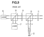
- FIG. 9 shows the system which comprises two lasers 16 and 17 each of which produces a laser beam having a different wavelength.
- the laser beam emitted from the laser 16 is focused on a disc (not shown) through a beam splitter 18, a half-wave plate 19, a beam splitter 20, a quarter-wave plate 21, and an objective (not shown).
- the reflected beam from the disc is reflected on the beam splitter 20 and focused on photodetector 22.
- the laser beam emitted from the laser 17 is reflected on the beam splitter 18 and focused on the disc in the same manner as the beam from the laser 16.
- the reflected beam from the disc is focused on the photodetector 22 in the same manner as described above.
- the beam having the large spot diameter is used for reproducing the information in the high recording density, crosstalk is produced between adjacent tracks and pits of short pitch can not be reproduced because of the large spot.
- the beam having the small spot diameter is used on the disc having the low recording density, intermodulation is generated, so that it is impossible to properly reproduce the information on the disc.
- An object of the present invention is to provide an optical pickup which is simple in construction, thereby reducing the size of the pickup and the manufacturing cost.
- Another object of the present invention is to provide a pickup which may record and reproduce information on optical discs having different recording densities with respect to each other.
- an optical pickup for an optical disc player having a laser for emitting a laser beam for optical discs which are different in recording density, comprising a beam splitter for dividing the laser beam from the laser into two beams, a first objective for focusing one of the laser beams on one of the optical discs, a beam expander for expanding an intensity distribution in the optical axis, and a second objective for focusing the expanded laser beam on the other disc.
- a laser beam is emitted from a single laser for recording and reproducing information on an optical disc having different recording densities.
- the laser beam is splitted into different directions.
- the beam in one of the directions is focused on the optical disc through a first objective.
- the beam in the other direction is expanded along the optical axis by a beam expander to reduce the diameter of the beam and the beam is focused on the disc through a second objective.
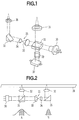
- a semiconductor laser 30 emits a laser beam which is reflected on a half mirror 31 as a beam splitter, and hence divided into two directions.
- the laser beam in one of the directions is focused on a first optical disc (not shown) through an objective 32.
- the reflected beam from the disc is focused on a photodetector 37 through the objective 32, the half mirror 31, and a cylindrical lens 29.
- the beam passing through the half mirror 31 enters a beam expander 25 comprising a large lens 33 and a small lens 34.
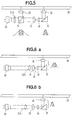
- the beam expander 25 has a function to expand the intensity (power) distribution of the light having a Gaussian distribution in the direction of the optical axis thereby narrowing the distribution as shown in Fig. 2.
- the beam is reflected on a prism 35 in a vertical direction and focused on a second disc through an objective 36.
- the second disc has a lower recording density than the first disc.
- the pickup may be used for a single disc having different areas, the recording densities of which are different from each other.
- the reflected beam from the disc passes through the objective 36, prism 34, expander 25, and half mirror 31, and is focused on the photodetector 37 through the lens 29.
- the objectives 32 and 36 have the same numerical aperture (NA). The operation of the pickup is described with reference to Fig. 2.
- the laser beam emitted from the semiconductor laser 30 is reflected on the half mirror 31 and divided into the different directions, namely to the objective 32 and to the expander 25.
- the laser beam directed to the objective 32 has a wide width Gaussian distribution A in intensity distribution.
- the skirt of the Gaussian distribution has a substantially larger width than the diameter of the objective 32. Consequently, the side skirt of the distribution is largely truncated by the objective so that a central portion approximate to a plane wave shown by the hatching is irradiated onto the disc.
- the laser beam directed to the objective 36 is expanded in the optical axis as shown by the distribution B.
- the skirt of the distribution is slightly truncated.
- the spot diameter is determined by the constant k.
- the constant k changes with the diameter of the beam profile incident on the lens. If the position of the profile on the distribution is at a position a where the light intensity is one-half of the central portion, the constant k is 0.5.
- the constant k at a position (position e-2) is 0.8, and 1.2 at a zero position c. Namely, the constant k decreases as the amount of the truncation increases. Therefore, the spot diameter reduces as the truncation increases.
- the spot of the beam focused on a disc 38 through the objective 36 has a large diameter because of the small truncation, and the spot of the beam passing through the objective 32 has a small diameter because of a large truncation.
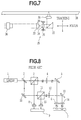
- the powers of the beams focused on the discs through the objectives 32 and 36 are equalized as described hereinafter.
- the separation of the reflected beam for the photodetector 37 is performed by polarizing the beam.
- a collimator lens 40 is provided in front of the semiconductor laser 30, and a ⁇ /4-wave plate 31B is disposed at the incident side of the objective 36.
- the reflected beam from the disc 38 is polarized by the ⁇ /4-wave plate 31B in a direction perpendicular to the paper of the figure as shown by marks +.
- the polarized reflected beam passes the beam expander and is reflected on the half mirror 31.
- the beam is applied to a photodetector 37a passing through a polarizing beam splitter 41.
- the reflected beam passing the objective 32 passes the half mirror 31 as shown by dotted line arrows and is reflected by the splitter 41 to a photodetector 37b.
- a ⁇ /2-wave plate 31A is disposed in front of the semiconductor laser 30 to rotate the polarized light of the beam at 90 degrees so that the beam reflected only in one direction from the half mirror 31 is transmitted or reflected.
- the optical pickup is provided with a single laser and means for focusing the laser beam from the laser on the disc with different spot diameters. Therefore, the pickup is simplified in construction, and the size and the manufacturing cost thereof are reduced.
- FIGs. 6a and 6b show another embodiment of the pickup.
- a lens 33A is variably disposed at the incident side of the large lens 33 of the expander 25 so as to form a zoom lens.
- Fig. 7 shows a further embodiment.
- actuators 39 are provided on the small lens 34 of the expander 25 to move the lens 34 in the focus direction and the tracking direction.
- the weight of the optical pickup is reduced, so that the pickup can be moved at a high speed when searching the recorded information.
Applications Claiming Priority (2)
| Application Number | Priority Date | Filing Date | Title |
|---|---|---|---|
| JP4076023A JPH05242521A (ja) | 1992-02-27 | 1992-02-27 | 光ディスクプレーヤ |
| JP76023/92 | 1992-02-27 |
Publications (2)
| Publication Number | Publication Date |
|---|---|
| EP0558052A1 true EP0558052A1 (de) | 1993-09-01 |
| EP0558052B1 EP0558052B1 (de) | 1997-07-30 |
Family
ID=13593233
Family Applications (1)
| Application Number | Title | Priority Date | Filing Date |
|---|---|---|---|
| EP93103094A Expired - Lifetime EP0558052B1 (de) | 1992-02-27 | 1993-02-26 | Optischer Abtastkopf für optisches Wiedergabegerät |
Country Status (4)
| Country | Link |
|---|---|
| US (1) | US5381394A (de) |
| EP (1) | EP0558052B1 (de) |
| JP (1) | JPH05242521A (de) |
| DE (1) | DE69312527T2 (de) |
Cited By (9)
| Publication number | Priority date | Publication date | Assignee | Title |
|---|---|---|---|---|
| WO1994022138A1 (de) * | 1993-03-17 | 1994-09-29 | Deutsche Thomson-Brandt Gmbh | Kompatibles aufzeichnungs- und/oder wiedergabegerät |
| EP0737964A1 (de) * | 1995-04-14 | 1996-10-16 | Kabushiki Kaisha Toshiba | Gerät und Verfahren zur Wiedergabe von Informationen aus unterschiedlichen optischen Platten und Aufzeichnungs-/Wiedergabegerät für optische Platten |
| EP0753845A1 (de) * | 1995-01-31 | 1997-01-15 | Sony Corporation | Vorrichtung zur wiedergabe eines optischen aufzeichnungsmediums |
| EP0777222A1 (de) * | 1995-11-29 | 1997-06-04 | Sharp Kabushiki Kaisha | Optische Abtastvorrichtung mit zwei Objektivlinsen |
| EP0777219A1 (de) * | 1995-11-30 | 1997-06-04 | Nec Corporation | Optische Kopfanordnung |
| EP0778564A1 (de) * | 1995-12-08 | 1997-06-11 | Balzers und Leybold Deutschland Holding Aktiengesellschaft | Vorrichtung zum Belichten eines kreisscheibenförmigen Substrates |
| EP0775998A3 (de) * | 1995-11-22 | 1998-05-13 | Pioneer Electronic Corporation | Regeleinrichtung für optische Abtastvorrichtung |
| EP0902945A1 (de) * | 1996-05-31 | 1999-03-24 | Cinram Inc. | System zur einstellung der punktgrösse in einem optischen aufzeichnungssystem |
| US6618345B1 (en) * | 1995-09-28 | 2003-09-09 | Sony Corporation | Reduced crosstalk optical recording medium using an optically related track pitch |
Families Citing this family (11)
| Publication number | Priority date | Publication date | Assignee | Title |
|---|---|---|---|---|
| USRE39025E1 (en) * | 1995-08-30 | 2006-03-21 | Samsung Electronics Co., Ltd. | Lens device including a light controlling mechanism and an optical pickup apparatus using a lens device |
| KR100234257B1 (ko) * | 1995-08-30 | 1999-12-15 | 윤종용 | 대물렌즈 장치 및 안정된 포커스 서보 신호를 얻는방법 및 이를 적용한 광픽업 장치 및 두께가 다른 디스크를 판별하는 방법 및 두께가 다른 디스크로부터 정보를 재생하고 기록하는 방법 |
| JP3048912B2 (ja) * | 1996-02-06 | 2000-06-05 | 日本電気株式会社 | 光ヘッド装置 |
| JP3848731B2 (ja) * | 1997-04-21 | 2006-11-22 | パイオニア株式会社 | 光ヘッド |
| DE19983100T1 (de) | 1998-04-06 | 2001-05-31 | Imation Corp | Herstellung eines umgekehrten optischen Masters für Datenspeicherplatten |
| US20050213482A1 (en) * | 2004-03-24 | 2005-09-29 | Imation Corp. | Multi-track mastering techniques |
| US20060073422A1 (en) * | 2004-09-28 | 2006-04-06 | Imation Corp. | Portable conformable deep ultraviolet master mask |
| US20060110568A1 (en) * | 2004-11-23 | 2006-05-25 | Imation Corp. | Multi-layers optical data storage disk masters |
| US7427466B2 (en) * | 2004-11-29 | 2008-09-23 | Imation Corp. | Anti-reflection optical data storage disk master |
| US20090274020A1 (en) * | 2006-11-24 | 2009-11-05 | Nec Corporation | Optical head unit and optical information recording/reproducing apparatus |
| JP5225005B2 (ja) * | 2008-02-08 | 2013-07-03 | 三菱電機株式会社 | 光ピックアップ装置及び光ディスク装置 |
Citations (3)
| Publication number | Priority date | Publication date | Assignee | Title |
|---|---|---|---|---|
| EP0040995A2 (de) * | 1980-05-28 | 1981-12-02 | Thomson-Csf | Optische Aufnahme-Wiedergabe-Vorrichtung für einen Informationsträger |
| EP0189948A1 (de) * | 1985-01-22 | 1986-08-06 | Koninklijke Philips Electronics N.V. | Aufzeichnungsträger mit einer optisch detektierbaren Reliefstruktur der Führungsspurteile und Sektoradressen und Gerät zur Herstellung dieser Struktur |
| EP0240002A2 (de) * | 1986-04-02 | 1987-10-07 | Dainippon Screen Mfg. Co., Ltd. | Laseraufzeichnungsvorrichtung |
Family Cites Families (5)
| Publication number | Priority date | Publication date | Assignee | Title |
|---|---|---|---|---|
| JPS6149731A (ja) * | 1984-08-13 | 1986-03-11 | Orion Mach Co Ltd | 複合金属板の曲げ加工方法 |
| US4712207A (en) * | 1985-03-18 | 1987-12-08 | Rca Corporation | Apparatus for erasing information on a reversible optical recording medium |
| JPS61220173A (ja) * | 1985-03-26 | 1986-09-30 | Toshiba Corp | 情報記録方法及び装置 |
| US5223970A (en) * | 1989-03-16 | 1993-06-29 | Asahi Kogaku Kogyo Kabushiki Kaisha | Optical axis adjusting mechanism and method for optical information recording and reproducing device, and jig therefor |
| US5235581A (en) * | 1990-08-09 | 1993-08-10 | Matsushita Electric Industrial Co., Ltd. | Optical recording/reproducing apparatus for optical disks with various disk substrate thicknesses |
-
1992
- 1992-02-27 JP JP4076023A patent/JPH05242521A/ja active Pending
-
1993
- 1993-01-08 US US08/001,972 patent/US5381394A/en not_active Expired - Lifetime
- 1993-02-26 EP EP93103094A patent/EP0558052B1/de not_active Expired - Lifetime
- 1993-02-26 DE DE69312527T patent/DE69312527T2/de not_active Expired - Fee Related
Patent Citations (3)
| Publication number | Priority date | Publication date | Assignee | Title |
|---|---|---|---|---|
| EP0040995A2 (de) * | 1980-05-28 | 1981-12-02 | Thomson-Csf | Optische Aufnahme-Wiedergabe-Vorrichtung für einen Informationsträger |
| EP0189948A1 (de) * | 1985-01-22 | 1986-08-06 | Koninklijke Philips Electronics N.V. | Aufzeichnungsträger mit einer optisch detektierbaren Reliefstruktur der Führungsspurteile und Sektoradressen und Gerät zur Herstellung dieser Struktur |
| EP0240002A2 (de) * | 1986-04-02 | 1987-10-07 | Dainippon Screen Mfg. Co., Ltd. | Laseraufzeichnungsvorrichtung |
Non-Patent Citations (4)
| Title |
|---|
| PATENT ABSTRACTS OF JAPAN vol. 11, no. 173 (P-582)4 June 1987 & JP-A-62 3 441 ( TOSHIBA CORP. ) 9 January 1987 * |
| PATENT ABSTRACTS OF JAPAN vol. 11, no. 283 (P-615)12 September 1987 & JP-A-62 078 740 ( MATSUSHITA ELECTRIC IND CO ) 11 April 1987 * |
| PATENT ABSTRACTS OF JAPAN vol. 16, no. 53 (P-1309)10 February 1992 & JP-A-32 52 923 ( TOSHIBA CORP. ) 12 November 1991 * |
| PATENT ABSTRACTS OF JAPAN vol. 9, no. 257 (P-396)15 October 1985 & JP-A-60 106 031 ( MATSUSHITA DENKI SANGYO K.K. ) 11 June 1985 * |
Cited By (18)
| Publication number | Priority date | Publication date | Assignee | Title |
|---|---|---|---|---|
| US6198706B1 (en) * | 1993-03-17 | 2001-03-06 | Deutsche Thomson-Brandt Gmbh | Optical format compatible recording and/or playback device |
| WO1994022138A1 (de) * | 1993-03-17 | 1994-09-29 | Deutsche Thomson-Brandt Gmbh | Kompatibles aufzeichnungs- und/oder wiedergabegerät |
| US6034936A (en) * | 1995-01-31 | 2000-03-07 | Sony Corporation | Optical recording medium reproducing apparatus for reproducing low density and high density recording media |
| EP0753845A1 (de) * | 1995-01-31 | 1997-01-15 | Sony Corporation | Vorrichtung zur wiedergabe eines optischen aufzeichnungsmediums |
| US6400661B1 (en) | 1995-01-31 | 2002-06-04 | Sony Corporation | Optical recording medium reproducing apparatus |
| US6167007A (en) * | 1995-01-31 | 2000-12-26 | Sony Corporation | Optical recording medium reproducing apparatus |
| EP0753845A4 (de) * | 1995-01-31 | 1998-12-02 | Sony Corp | Vorrichtung zur wiedergabe eines optischen aufzeichnungsmediums |
| EP0737964A1 (de) * | 1995-04-14 | 1996-10-16 | Kabushiki Kaisha Toshiba | Gerät und Verfahren zur Wiedergabe von Informationen aus unterschiedlichen optischen Platten und Aufzeichnungs-/Wiedergabegerät für optische Platten |
| US6850476B2 (en) * | 1995-09-28 | 2005-02-01 | Sony Corporation | Optical recording medium |
| US6618345B1 (en) * | 1995-09-28 | 2003-09-09 | Sony Corporation | Reduced crosstalk optical recording medium using an optically related track pitch |
| US5835466A (en) * | 1995-11-22 | 1998-11-10 | Pioneer Electronic Corporation | Optical system for optical disc having first and second information |
| EP0775998A3 (de) * | 1995-11-22 | 1998-05-13 | Pioneer Electronic Corporation | Regeleinrichtung für optische Abtastvorrichtung |
| EP0777222A1 (de) * | 1995-11-29 | 1997-06-04 | Sharp Kabushiki Kaisha | Optische Abtastvorrichtung mit zwei Objektivlinsen |
| EP0777219A1 (de) * | 1995-11-30 | 1997-06-04 | Nec Corporation | Optische Kopfanordnung |
| DE19545857A1 (de) * | 1995-12-08 | 1997-06-12 | Leybold Ag | Vorrichtung zum Belichten eines kreisscheibenförmigen Substrates |
| EP0778564A1 (de) * | 1995-12-08 | 1997-06-11 | Balzers und Leybold Deutschland Holding Aktiengesellschaft | Vorrichtung zum Belichten eines kreisscheibenförmigen Substrates |
| EP0902945A4 (de) * | 1996-05-31 | 1999-09-22 | Cinram Inc | System zur einstellung der punktgrösse in einem optischen aufzeichnungssystem |
| EP0902945A1 (de) * | 1996-05-31 | 1999-03-24 | Cinram Inc. | System zur einstellung der punktgrösse in einem optischen aufzeichnungssystem |
Also Published As
| Publication number | Publication date |
|---|---|
| DE69312527D1 (de) | 1997-09-04 |
| DE69312527T2 (de) | 1998-03-05 |
| US5381394A (en) | 1995-01-10 |
| EP0558052B1 (de) | 1997-07-30 |
| JPH05242521A (ja) | 1993-09-21 |
Similar Documents
| Publication | Publication Date | Title |
|---|---|---|
| EP0558052B1 (de) | Optischer Abtastkopf für optisches Wiedergabegerät | |
| US5610880A (en) | Optical disc system and optical disk therefor | |
| US5295125A (en) | Optical head device for recording/reproduction for recording medium using plural light spots | |
| US6285646B1 (en) | Optical pickup using objective lens compatible with a plurality of optical disks | |
| US5043960A (en) | Overwritable magneto-optic recording and reproducing apparatus | |
| EP0184750B1 (de) | Optische Aufnahme- und Wiedergabevorrichtung | |
| EP0855702B1 (de) | Optische Platte | |
| JPH0777025B2 (ja) | 光学的記録再生装置 | |
| KR19980022835A (ko) | 2광원을 이용한 홀로그램 광픽업 | |
| EP0731454B1 (de) | Optisches aufzeichnungsverfahren, optisches aufzeichnungsgerät und optisches aufzeichnungsmedium | |
| JPH0696463A (ja) | 光ディスク演奏装置 | |
| JP2950500B2 (ja) | 厚さが異なるディスクの互換のための記録再生用光ピックアップ | |
| US5986993A (en) | Optical pickup device having a diaphram with a predetermined aperture | |
| EP1213714A2 (de) | Optisches Informationsaufzeichnungsmedium, das mehrere Informationsaufzeichnungsschichten enthält | |
| EP0918321B1 (de) | Mit optischen Aufzeichnungsmedien kompatibler optischer Abtastkopf | |
| EP0859357B1 (de) | Objektivlinse, Wiedergabegerät und Wiedergabemethode | |
| US5784345A (en) | Optical pickup device for eliminating unwanted data | |
| US5144615A (en) | Apparatus and method for recording and reproducing multi-level information | |
| US6342976B1 (en) | Luminous flux diameter variable type objective lens and optical apparatus using the same | |
| US6094308A (en) | Diffraction type filter having a wavelength selectivity | |
| US5615050A (en) | Optical system with reduced focus spot size | |
| EP0737964A1 (de) | Gerät und Verfahren zur Wiedergabe von Informationen aus unterschiedlichen optischen Platten und Aufzeichnungs-/Wiedergabegerät für optische Platten | |
| JPH0291829A (ja) | 光ヘッド装置 | |
| US5477521A (en) | Prism for an optical pickup of an optical recording and reproducing device | |
| JP2990067B2 (ja) | 光学式情報記録再生装置 |
Legal Events
| Date | Code | Title | Description |
|---|---|---|---|
| PUAI | Public reference made under article 153(3) epc to a published international application that has entered the european phase |
Free format text: ORIGINAL CODE: 0009012 |
|
| AK | Designated contracting states |
Kind code of ref document: A1 Designated state(s): DE FR GB |
|
| 17P | Request for examination filed |
Effective date: 19930722 |
|
| 17Q | First examination report despatched |
Effective date: 19950707 |
|
| GRAG | Despatch of communication of intention to grant |
Free format text: ORIGINAL CODE: EPIDOS AGRA |
|
| GRAH | Despatch of communication of intention to grant a patent |
Free format text: ORIGINAL CODE: EPIDOS IGRA |
|
| GRAH | Despatch of communication of intention to grant a patent |
Free format text: ORIGINAL CODE: EPIDOS IGRA |
|
| GRAA | (expected) grant |
Free format text: ORIGINAL CODE: 0009210 |
|
| AK | Designated contracting states |
Kind code of ref document: B1 Designated state(s): DE FR GB |
|
| ET | Fr: translation filed | ||
| REF | Corresponds to: |
Ref document number: 69312527 Country of ref document: DE Date of ref document: 19970904 |
|
| REG | Reference to a national code |
Ref country code: GB Ref legal event code: 746 Effective date: 19980107 |
|
| PLBE | No opposition filed within time limit |
Free format text: ORIGINAL CODE: 0009261 |
|
| STAA | Information on the status of an ep patent application or granted ep patent |
Free format text: STATUS: NO OPPOSITION FILED WITHIN TIME LIMIT |
|
| 26N | No opposition filed | ||
| REG | Reference to a national code |
Ref country code: FR Ref legal event code: D6 |
|
| REG | Reference to a national code |
Ref country code: GB Ref legal event code: IF02 |
|
| PGFP | Annual fee paid to national office [announced via postgrant information from national office to epo] |
Ref country code: GB Payment date: 20080220 Year of fee payment: 16 Ref country code: DE Payment date: 20080221 Year of fee payment: 16 |
|
| PGFP | Annual fee paid to national office [announced via postgrant information from national office to epo] |
Ref country code: FR Payment date: 20080208 Year of fee payment: 16 |
|
| GBPC | Gb: european patent ceased through non-payment of renewal fee |
Effective date: 20090226 |
|
| REG | Reference to a national code |
Ref country code: FR Ref legal event code: ST Effective date: 20091030 |
|
| PG25 | Lapsed in a contracting state [announced via postgrant information from national office to epo] |
Ref country code: DE Free format text: LAPSE BECAUSE OF NON-PAYMENT OF DUE FEES Effective date: 20090901 |
|
| PG25 | Lapsed in a contracting state [announced via postgrant information from national office to epo] |
Ref country code: GB Free format text: LAPSE BECAUSE OF NON-PAYMENT OF DUE FEES Effective date: 20090226 Ref country code: FR Free format text: LAPSE BECAUSE OF NON-PAYMENT OF DUE FEES Effective date: 20090302 |