EP0557995B1 - Plant for the pressurized slip casting of ceramic products, in particular of toilet bowls - Google Patents
Plant for the pressurized slip casting of ceramic products, in particular of toilet bowls Download PDFInfo
- Publication number
- EP0557995B1 EP0557995B1 EP93102964A EP93102964A EP0557995B1 EP 0557995 B1 EP0557995 B1 EP 0557995B1 EP 93102964 A EP93102964 A EP 93102964A EP 93102964 A EP93102964 A EP 93102964A EP 0557995 B1 EP0557995 B1 EP 0557995B1
- Authority
- EP
- European Patent Office
- Prior art keywords
- mould part
- frame
- mould
- clamping frame
- clamping
- Prior art date
- Legal status (The legal status is an assumption and is not a legal conclusion. Google has not performed a legal analysis and makes no representation as to the accuracy of the status listed.)
- Expired - Lifetime
Links
Images


Classifications
-
- B—PERFORMING OPERATIONS; TRANSPORTING
- B28—WORKING CEMENT, CLAY, OR STONE
- B28B—SHAPING CLAY OR OTHER CERAMIC COMPOSITIONS; SHAPING SLAG; SHAPING MIXTURES CONTAINING CEMENTITIOUS MATERIAL, e.g. PLASTER
- B28B1/00—Producing shaped prefabricated articles from the material
- B28B1/26—Producing shaped prefabricated articles from the material by slip-casting, i.e. by casting a suspension or dispersion of the material in a liquid-absorbent or porous mould, the liquid being allowed to soak into or pass through the walls of the mould; Moulds therefor ; specially for manufacturing articles starting from a ceramic slip; Moulds therefor
- B28B1/265—Producing shaped prefabricated articles from the material by slip-casting, i.e. by casting a suspension or dispersion of the material in a liquid-absorbent or porous mould, the liquid being allowed to soak into or pass through the walls of the mould; Moulds therefor ; specially for manufacturing articles starting from a ceramic slip; Moulds therefor pressure being applied on the slip in the filled mould or on the moulded article in the mould, e.g. pneumatically, by compressing slip in a closed mould
- B28B1/266—Means for counteracting the pressure being applied on the slip or on the moulded article in the mould, e.g. means for clamping the moulds parts together in a frame-like structure
Definitions
- a system of this type known as a press, with two cross-shaped portals arranged at right angles to each other is known, on each of which two molded slides are guided on horizontal rails.
- a hanging frame extending downward from the associated portal is attached to each slide, on which a mounting plate for mounting a molded part is arranged.
- Each of the mounting plates can be advanced by hydraulic cylinders relative to the associated hanging frame in the direction of the center of the press and retractable in the opposite direction.
- a lifting device is arranged in a foundation recess, which carries a lower molded part, which together with the molded parts attached to the four clamping plates results in a complete casting mold.
- sanitary articles in particular toilet bowls
- the mold is closed for die casting by moving the carriages guided on the portals in the direction of the press center until the mold parts arranged on the clamping plates come into contact with one another.
- the lower mold part is raised by means of the lifting device, so that finally a mold cavity is delimited by the mold parts.
- the hanging frames must be locked with mechanical locking elements fixed in the middle of the press and then the clamping plates must be pushed forward a limited amount relative to the slides and the clamping plate for the lower molded part upwards, so that the molded parts attached to the platen abut each other with a predetermined closing pressure.
- a further die casting device known from DE-A-2112759, which has a base plate, a vertical head plate fastened thereon, a foot plate arranged at a distance parallel thereto and four horizontal spars which are fastened to the two plates mentioned and a sliding plate parallel to them.
- the sliding plate is attached to the base plate supported hydraulic piston-cylinder unit displaceable towards the head plate and carries a casting core-like molded part.
- a platen is pivotally mounted about a horizontal pivot axis, approximately at the height of the lower spars, at right angles to this and is articulated to a piston-cylinder unit which is supported on the head plate.
- a second, trough-like molded part is attached to the clamping plate.
- a closed die-casting mold is formed from the two molded parts by bringing the sliding plate closer to the head plate, which is filled with slip. After the pressure holding time and the subsequent standing time have elapsed, the sliding plate together with the core-like molded part is withdrawn in the direction of the base plate and then the clamping plate is pivoted down between the two lower bars and the resulting molded part is placed on a conveyor.
- the invention has for its object to provide a system for die casting ceramic moldings, in particular toilet bowls, with increased performance.
- clamping devices arranged on the clamping frame do not have to remain unused after the pressure holding time of the casting mold or casting molds that have held them together until the subsequent service life has elapsed, but can be used immediately for clamping one or more further pressure casting molds.
- the space around the first-mentioned die or group of such molds is already completely free of clamping devices before the end of the service life, so that the molded parts are immediately accessible, and any necessary reworking of the molded parts can be carried out without delay and the molded parts can be removed.
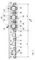
- the system shown includes six die-casting molds 10, each with a pair of molded parts 12, 14 and two cores 16 and 18, which together enclose a mold space for die-casting a molding 20, in the example shown a toilet bowl.
- the two molded parts 12 and 14 of each die are attached to a molded slide 22 and 24, respectively, which has a holder 26 and 28 for this purpose.
- the two molding slides 22 and 24 for each die 10 are mounted and guided on a common molding guide 30; a total of six molded part guides 30 aligned with one another are provided.
- Each molded part guide 30 has a first horizontal rod 32, which is ground in a circular cylinder and is fastened with its two ends to a stand 34 in each case.
- a second rod 36 extends parallel to the first rod 32 and in the position according to FIGS. 2 and 3 below it, but ends shortly before the adjacent stands 34 and is firmly connected to the first rod 32 at each end by a yoke 38 is.
- One of the two yokes 38 belonging to each molded part guide 30 is connected to a swivel drive 40 which, in the example shown, is formed by a hydraulic or pneumatic piston-cylinder unit and is designed such that it swivels the two yokes 38 together with the second rod 36 about the first rod 32 can, namely from the position shown in FIGS.
- Each of the molding slides 22 and 24 is connected to the adjacent yoke 38 by a sliding drive 46 and 48, respectively, and these sliding drives - again piston cylinder units are shown - are controlled so that the molding slides 22 and 24 for closing the die 10 towards each other and for opening are movable away from each other.
- the system also includes a clamping frame 50 which is formed from a plurality of longitudinal beams 52 and cross beams 54 welded to one another, as well as vertical end walls 56 and partition walls 58.
- the clamping frame 50 is mounted on a frame slide 60 so as to be pivotable about a horizontal pivot axis 62 parallel to the molded part guides 30 and is connected to the frame slide 60 by a pivot drive 64.
- the pivot drive 64 is designed so that the clamping frame 50 from the operating position shown in FIGS.
- the frame slide 60 is guided with top rollers 66 and side rollers 68 arranged in sets on a horizontal frame guide 70 which extends parallel to the pivot axis 62 and to the molded part guides 30.
- a rack 72 in which a pinion 74 engages, is fastened to the underside of the frame guide 70.
- the pinion 74 can be driven by a motor 76 arranged on the frame slide 60, and this motor is controlled so that it can be moved back and forth between a first casting station 78 and a second casting station 80.
- Each of the two casting stations 78 and 80 contains three of the die casting molds 10 shown in FIG. 1 together with the associated molding slide 22 and 24.
- the clamping frame 50 thus either encloses, as shown in FIG. 1, the three die casting molds arranged to the right of the center of the system 10 or the three die casting molds 10 to the left of it.
- Left clamping devices 82 and right clamping devices 84 and front clamping devices 86 and rear clamping devices 88 are arranged on the clamping frame 50 and in such a number that the molded parts 12 and 14 and cores 16 and 18 of each of the three die casting molds 10 enclosed by the clamping frame 50 can be clamped together by means of sixteen clamping devices are.
- a mobile core pulling device 90 of a known type is provided, which according to FIG. 1 is just in the first casting station 78 in order to turn the front core 16 and one with one gripper 92 from one of the die casting molds 10 arranged there another gripper 94 to pull the rear core 18.
- the molded parts 12 and 14 are moved away from one another by moving the molded part slides 22 and 24 in opposite directions, so that the associated molded article 20 is released so that it can then dry on the associated shrink plate 96.
- the shrinkage plates 96 are smooth on their upper side, so that they do not hinder the shrinkage of the moldings 20 which occurs during drying.
- the die casting molds 10 in the second casting station 80 are filled with slip under pressure and then remain clamped together by the clamping frame 50 until the pressure holding time has elapsed.
- the clamping devices 82, 84, 86 and 88 are depressurized and the clamping frame 50 is pivoted upwards into its rest position according to FIG. 4.
- it is sufficient it is that the molded parts 12 and 14 are held together by the sliding drives 46 and 48 engaging on the associated molded slide 22 and 24 with a small force which would not have withstood the casting pressure by itself.
- the clamping frame 50 is moved from the second casting station 80 into the first casting station 78 and lowered into its operating position.
- their cores 16 and 18 are drawn by means of the core pulling device 90 and then the mold parts 12 and 14 together with the moldings 20 held between them are pivoted over the conveyor 44 in the manner described, so that now these moldings are also placed on a shrinkage plate 96 each.
Description
Die Erfindung betrifft eine Anlage zum Druckgießen keramischer Formlinge, insbesondere WC-Schüsseln, mit
- paarweise zusammengehörigen Formteilschlitten, die entlang einer Formteilführung gegeneinander verschiebbar sind und je ein Formteil tragen, und
- Spannvorrichtungen zum Zusammenspannen der Formteile.
- paired molding slides that are mutually displaceable along a molding guide and each carry a molding, and
- Clamping devices for clamping the molded parts.
Aus der DE-A-3740163 ist eine als Presse bezeichnete Anlage dieser Gattung mit zwei kreuzförmig, rechtwinklig zueinander angeordneten Portalen bekannt, an denen je zwei Formteilschlitten auf waagerechten Schienen geführt sind. An jedem Schlitten ist ein sich vom zugehörigen Portal nach unten erstreckender Hängerahmen befestigt, an dem eine Aufspannplatte zum Aufspannen eines Formteils angeordnet ist. Jede der Aufnahmeplatten ist durch Hydraulikzylinder relativ zum zugehörigen Hängerahmen in Richtung auf die Pressenmitte vorrückbar und in entgegengesetzter Richtung zurückziehbar. Unterhalb der durch die sich kreuzenden Portale bestimmten Portalmitte ist in einer Fundamentausnehmung eine Hubeinrichtung angeordnet, die ein unteres Formteil trägt, welches zusammen mit den an den vier Aufspannplatten befesigten Formteilen eine vollständige Gießform ergibt. Mit dieser bekannten Anlage lassen sich Sanitärartikel, insbesondere WC-Schüsseln, gießen, die zur Formung mehr als zwei Formteile benötigen. Die Form wird zum Druckgießen dadurch geschlossen, daß die an den Portalen geführten Schlitten in Richtung auf die Pressenmitte bewegt werden, bis die auf den Aufspannplatten angeordneten Formteile in Anlage aneinander gelangen. Gleichzeitig wird mittels der Hubeinrichtung das untere Formteil angehoben, so daß schließlich durch die Formteile ein Formhohlraum begrenzt ist. Ehe dieser mit keramischem Schlicker unter Druck gefüllt werden kann, müssen die Hängerahmen mit in der Pressenmitte fest angeordneten mechanischen Verriegelungselementen verriegelt werden und anschließend die Aufspannplatten relativ zu den Schlitten um ein begrenztes Maß nach vorne sowie die Aufspannplatte für das untere Formteil nach oben gedrückt werden, so daß die an den Aufspannplatten befestigten Formteile mit einem vorbestimmten Schließdruck aneinanderliegen.From DE-A-3740163 a system of this type, known as a press, with two cross-shaped portals arranged at right angles to each other is known, on each of which two molded slides are guided on horizontal rails. A hanging frame extending downward from the associated portal is attached to each slide, on which a mounting plate for mounting a molded part is arranged. Each of the mounting plates can be advanced by hydraulic cylinders relative to the associated hanging frame in the direction of the center of the press and retractable in the opposite direction. Below the portal center defined by the intersecting portals, a lifting device is arranged in a foundation recess, which carries a lower molded part, which together with the molded parts attached to the four clamping plates results in a complete casting mold. With this known system, sanitary articles, in particular toilet bowls, can be poured for molding need more than two molded parts. The mold is closed for die casting by moving the carriages guided on the portals in the direction of the press center until the mold parts arranged on the clamping plates come into contact with one another. At the same time, the lower mold part is raised by means of the lifting device, so that finally a mold cavity is delimited by the mold parts. Before this can be filled with ceramic slip under pressure, the hanging frames must be locked with mechanical locking elements fixed in the middle of the press and then the clamping plates must be pushed forward a limited amount relative to the slides and the clamping plate for the lower molded part upwards, so that the molded parts attached to the platen abut each other with a predetermined closing pressure.
Beim Druckgießen keramischer Formlinge genügt es im allgemeinen, den in einen Formhohlraum eingefüllten Schlicker während einer Druckhaltezeit, die je nach der angestrebten Scherbendicke in der Größenordnung von 10 bis 15 Min. liegt, unter Druck zu halten. Anschließend läßt man den überschüssigen Schlicker ablaufen, und dann muß der Formling sich während einer bestimmten Standzeit bei noch geschlossener Druckgießform verfestigen, ehe die Form geöffnet, der Formling entnommen und die Form dann für das Druckgießen eines weiteren Formlings hergerichtet werden kann. Als Summe der Zeit für all diese einzelnen Vorgänge ergibt sich eine Zykluszeit, in der bei der beschriebenen bekannten Anlage jeweils nur ein einziger Formling entsteht.When die-casting ceramic moldings, it is generally sufficient to hold the slip filled in a mold cavity under pressure for a pressure-holding time which is in the order of 10 to 15 minutes, depending on the desired thickness of the body. Then the excess slip is allowed to run off, and then the molding has to solidify for a certain period of time with the die still closed before the mold is opened, the molding is removed and the mold can then be prepared for the die-casting of another molding. The sum of the time for all these individual processes results in a cycle time in which only a single molding is produced in the known system described.
Entsprechendes gilt auch für eine weitere, aus der DE-A-2112759 bekannte Druckgießvorrichtung, die eine Grundplatte, eine auf dieser befestigte senkrechte Kopfplatte, eine im Abstand parallel dazu angeordnete Fußplatte und vier waagerechte Holme aufweist, die an den beiden genannten Platten befestigt sind und eine zu ihnen parallele Schiebeplatte führen. Die Schiebeplatte ist mittels einer an der Fußplatte abgestützten hydraulischen Kolbenzylindereinheit zur Kopfplatte hin verschiebbar und trägt ein gießkernartiges Formteil. An der Kopfplatte ist eine Aufspannplatte um eine waagerechte, etwa in Höhe der unteren Holme rechtwinklig zu dieser angeordnete Schwenkachse schwenkbar gelagert und gelenkig mit einer Kolbenzylindereinheit verbunden, die an der Kopfplatte abgestützt ist. An der Aufspannplatte ist ein zweites, wannenartiges Formteil befestigt. In jedem Arbeitszyklus wird aus den beiden Formteilen durch Annähern der Schiebeplatte an die Kopfplatte eine geschlossene Druckgießform gebildet, die mit Schlicker gefüllt wird. Nach Ablauf der Druckhaltezeit und der sich daran anschließenden Standzeit wird die Schiebeplatte samt kernartigem Formteil in Richtung zur Fußplatte zurückgezogen und anschließend wird die Aufspannplatte zwischen den beiden unteren Holmen hindurch nach unten geschwenkt und der entstandene Formling auf einem Förderer abgesetzt.The same also applies to a further die casting device known from DE-A-2112759, which has a base plate, a vertical head plate fastened thereon, a foot plate arranged at a distance parallel thereto and four horizontal spars which are fastened to the two plates mentioned and a sliding plate parallel to them. The sliding plate is attached to the base plate supported hydraulic piston-cylinder unit displaceable towards the head plate and carries a casting core-like molded part. On the head plate, a platen is pivotally mounted about a horizontal pivot axis, approximately at the height of the lower spars, at right angles to this and is articulated to a piston-cylinder unit which is supported on the head plate. A second, trough-like molded part is attached to the clamping plate. In each working cycle, a closed die-casting mold is formed from the two molded parts by bringing the sliding plate closer to the head plate, which is filled with slip. After the pressure holding time and the subsequent standing time have elapsed, the sliding plate together with the core-like molded part is withdrawn in the direction of the base plate and then the clamping plate is pivoted down between the two lower bars and the resulting molded part is placed on a conveyor.
Der Erfindung liegt die Aufgabe zugrunde, eine Anlage zum Druckgießen keramischer Formlinge, insbesondere WC-Schüsseln, mit erhöhter Leistungsfähigkeit zu schaffen.The invention has for its object to provide a system for die casting ceramic moldings, in particular toilet bowls, with increased performance.
Diese Aufgabe ist erfindungsgemäß ausgehend von einer Anlage der eingangs beschriebenen Gattung dadurch gelöst, daß
- die Spannvorrichtungen an einem von den Formteilschlitten getrennten Spannrahmen angeordnet sind, der zwischen einer Betriebsstellung, in der er mindestens ein Paar Formteile umschließt, und einer Ruhestellung, in der er diese Formteile freigibt, hin- und herbewegbar ist,
- mindestens ein zusätzliches Paar Formteile auf je einem zusätzlichen Formteilschlitten außerhalb des Spannrahmens angeordnet ist, solange dieser die erstgenannten Formteile umschließt, und
- in der Ruhestellung des Spannrahmens eine Relativbeweglichkeit zwischen Spannrahmen und Formteilschlitten gegeben ist, die es dem Spannrahmen ermöglicht, in Betriebsstellung wahlweise die erstgenannten Formteile oder die zusätzlichen Formteile zusammenzuspannen.
- the clamping devices are arranged on a clamping frame which is separate from the molded part slide and can be moved back and forth between an operating position in which it encloses at least one pair of molded parts and a rest position in which it releases these molded parts,
- at least one additional pair of molded parts is arranged on an additional molded part slide outside the clamping frame, as long as it surrounds the first-mentioned molded parts, and
- in the rest position of the clamping frame there is a relative mobility between the clamping frame and the molding slide, which enables the clamping frame to clamp together the first-mentioned molded parts or the additional molded parts in the operating position.
Damit wird erreicht, daß die am Spannrahmen angeordneten Spannvorrichtungen nach Ablauf der Druckhaltezeit der Gießform oder Gießformen, die sie zusammengehalten haben, nicht bis zum Ablauf der anschließenden Standzeit unbenutzt stehenbleiben müssen, sondern sofort zum Zusammenspannen einer oder mehrerer weiterer Druckgießformen verwendet werden können. Der Raum rings um die erstgenannte Druckgießform oder Gruppe solcher Formen ist schon vor Ablauf der Standzeit vollständig frei von Spannvorrichtungen, so daß die Formteile sofort zugänglich sind, etwa erforderliche Nacharbeiten an den Formlingen ohne Verzögerung durchgeführt und die Formlinge entnommen werden können.This ensures that the clamping devices arranged on the clamping frame do not have to remain unused after the pressure holding time of the casting mold or casting molds that have held them together until the subsequent service life has elapsed, but can be used immediately for clamping one or more further pressure casting molds. The space around the first-mentioned die or group of such molds is already completely free of clamping devices before the end of the service life, so that the molded parts are immediately accessible, and any necessary reworking of the molded parts can be carried out without delay and the molded parts can be removed.
Diese Vorteile sind grundsätzlich davon unabhängig, welche der zum Instellungbringen des Spannrahmens in bezug auf die Formteile erforderlichen Relativbewegungen dem Spannrahmen und welche davon den Formteilschlitten zugewiesen sind, und in welchen Richtungen im Raum diese Relativbewegungen stattfinden. Es hat sich jedoch als besonders vorteilhaft erwiesen, wenn der Spannrahmen Bewegungsmöglichkeiten gemäß den Ansprüche 2 bis 5 hat.These advantages are fundamentally independent of which of the relative movements required for positioning the clamping frame in relation to the molded parts are assigned to the clamping frame and which of these are assigned to the molded part slides, and in which directions in space these relative movements take place. However, it has proven to be particularly advantageous if the tenter frame has movement possibilities according to claims 2 to 5.
Vorteilhafte Ausgestaltungen der Formteilschlitten und der sie führenden und bewegenden Bauteile sind Gegenstand der Ansprüche 6 bis 9.Advantageous refinements of the molded part slide and the components which guide and move it are the subject of claims 6 to 9.
Ein Ausführungsbeispiel der Erfindung wird im folgenden anhand schematischer Zeichnungen mit weiteren Einzelheiten beschrieben. Es zeigen:
- Fig. 1
- die Draufsicht einer erfindungsgemäßen Anlage,
- Fig. 2
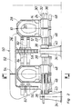
- die Vorderansicht in Richtung des Pfeils II in Fig. 1,
- Fig. 3
- eine teilweise als senkrechter Schnitt III-III in Fig. 2 dargestellte Seitenansicht der Anlage in einer Betriebsstellung und
- Fig. 4
- eine entsprechende Seitenansicht in einer Ruhestellung.
- Fig. 1
- the top view of a system according to the invention,
- Fig. 2
- the front view in the direction of arrow II in Fig. 1,
- Fig. 3
- a partially shown as a vertical section III-III in Fig. 2 side view of the system in an operating position and
- Fig. 4
- a corresponding side view in a rest position.
Zu der dargestellten Anlage gehören sechs Druckgießformen 10 mit je einem Paar Formteile 12, 14 sowie je zwei Kernen 16 und 18, die gemeinsam einen Formraum zum Druckgießen eines Formlings 20, im dargestellten Beispiel einer WC-Schüssel, umschließen. Die beiden Formteile 12 und 14 jeder Druckgießform sind an je einem Formteilschlitten 22 bzw. 24 befestigt, der zu diesem Zweck eine Halterung 26 bzw. 28 aufweist. Die beiden Formteilschlitten 22 und 24 für jede Druckgießform 10 sind auf einer gemeinsamen Formteilführung 30 gelagert und geführt; insgesamt sind sechs miteinander fluchtende Formteilführungen 30 vorgesehen.The system shown includes six die-
Jede Formteilführung 30 hat eine erste waagerechte Stange 32, die kreiszylindrisch geschliffen und mit ihren beiden Enden an je einem Ständer 34 befestigt ist. Parallel zu der ersten Stange 32 und in der Stellung gemäß Fig. 2 und 3 unterhalb davon erstreckt sich eine zweite Stange 36, die jedoch kurz vor den benachbarten Ständern 34 endet und an ihren Enden durch je ein Joch 38 mit der ersten Stange 32 fest verbunden ist. Eines der beiden zu jeder Formteilführung 30 gehörigen Joche 38 ist mit einem Schwenkantrieb 40 verbunden, der im dargestellten Beispiel von einer hydraulischen oder pneumatischen Kolbenzylindereinheit gebildet und so ausgelegt ist, daß er die beiden Joche 38 samt der zweiten Stange 36 um die erste Stange 32 schwenken kann, nämlich aus der in Fig. 2 und 3 abgebildeten Stellung, in der die beiden Stangen senkrecht übereinanderliegen, in die Stellung gemäß Fig. 4, in der die beiden Stangen nebeneinanderliegen. An der Schwenkung nehmen die beiden zugehörigen Formteilschlitten 22 und 24 teil, die auf den beiden Stangen 32 und 36 geführt sind. Die Stellung gemäß Fig. 2 und 3 ist eine Gießstellung, die dadurch festgelegt ist, daß die beiden Formteilschlitten 22 und 24 auf einer Säule 42 ruhen. Die Stellung gemäß Fig. 4 dient zur Übergabe des gegossenen Formlings 20 an einen Förderer 44.Each molded
Jeder der Formteilschlitten 22 und 24 ist durch einen Verschiebeantrieb 46 bzw. 48 mit dem benachbarten Joch 38 verbunden, und diese Verschiebeantriebe - dargestellt sind wiederum Kolbenzylindereinheiten - sind so gesteuert, daß die Formteilschlitten 22 und 24 zum Schließen der Druckgießform 10 zueinander hin und zum Öffnen voneinander weg bewegbar sind.Each of the
Zu der Anlage gehört ferner ein Spannrahmen 50, der aus mehreren miteinander verschweißten Längsträgern 52 und Querträgern 54 sowie senkrechten Stirnwänden 56 und Zwischenwänden 58 gebildet ist. Der Spannrahmen 50 ist an einem Rahmenschlitten 60 um eine waagerechte, zu den Formteilführungen 30 parallele Schwenkachse 62 schwenkbar gelagert und durch einen Schwenkantrieb 64 mit dem Rahmenschlitten 60 verbunden. Der Schwenkantrieb 64 ist so ausgelegt, daß der Spannrahmen 50 aus der in Fig. 1 bis 3 abgebildeten Betriebsstellung, in der er drei Druckgießformen 10 umschließt, um etwa 45° nach oben in eine Ruhestellung schwenkbar ist, in der die Formteilschlitten 22 und 24 samt daran befestigten Formteilen 12 und 14 in der beschriebenen Weise aus der Gießstellung in die Entnahmestellung, und umgekehrt, schwenkbar sind.The system also includes a
Der Rahmenschlitten 60 ist mit satzweise angeordneten oberen Rollen 66 und seitlichen Rollen 68 auf einer waagerechten Rahmenführung 70 geführt, die sich parallel zur Schwenkachse 62 und zu den Formteilführungen 30 erstreckt. An der Unterseite der Rahmenführung 70 ist eine Zahnstange 72 befestigt, in die ein Ritzel 74 eingreift. Das Ritzel 74 ist von einem am Rahmenschlitten 60 angeordneten Motor 76 antreibbar, und dieser ist so gesteuert, daß er zwischen einer ersten Gießstation 78 und einer zweiten Gießstation 80 hin- und herbewegbar ist. Jede der beiden Gießstationen 78 und 80 enthält drei der in Fig. 1 dargestellten Druckgießformen 10 samt zugehörigen Formteilschlitten 22 und 24. In seiner Betriebsstellung umschließt der Spannrahmen 50 somit entweder, wie in Fig. 1 dargestellt, die drei rechts der Mitte der Anlage angeordneten Druckgießformen 10 oder die drei links davon angeordneten Druckgießformen 10.The
Am Spannrahmen 50 sind linke Spannvorrichtungen 82 und rechte Spannvorrichtungen 84 sowie vordere Spannvorrichtungen 86 und hintere Spannvorrichtungen 88 derart und in solcher Anzahl angeordnet, daß die Formteile 12 und 14 sowie Kerne 16 und 18 jeder der drei vom Spannrahmen 50 umschlossenen Druckgießformen 10 mittels sechzehn Spannvorrichtungen zusammenspannbar sind.
Zum Ziehen und Setzen der Kerne 16 und 18 ist eine fahrbare Kernziehvorrichtung 90 bekannter Bauart vorgesehen, die gemäß Fig. 1 gerade in der ersten Gießstation 78 steht, um aus einer der dort angeordneten Druckgießformen 10 mit einem Greifer 92 den vorderen Kern 16 und mit einem weiteren Greifer 94 den hinteren Kern 18 zu ziehen. Dies geschieht nacheinander bei allen in der ersten Gießstation 78 stehenden Druckgießformen 10, und anschließend werden diese nacheinander über den Förderer 44 geschwenkt, so daß die in je einer dieser Druckgießformen zwischen den Formteilen 12 und 14 gehaltenen, bei einem vorangegangenen Arbeitszyklus gegossenen Formlinge 20 auf je einer auf dem Förderer 44 liegenden Schwundplatte 96 abgesetzt werden. Danach werden die Formteile 12 und 14 durch gegenläufiges Verschieben der Formteilschlitten 22 und 24 voneinander wegbewegt, so daß der zugehörige Formling 20 freigegeben wird, um dann auf der zugehörigen Schwundplatte 96 trocknen zu können. Die Schwundplatten 96 sind an ihrer Oberseite glatt, so daß sie das beim Trocknen eintretende Schwinden der Formlinge 20 nicht behindern.To pull and set the
Während des Entleerens der Druckgießformen 10 in der ersten Gießstation 78 werden die Druckgießformen 10 in der zweiten Gießstation 80 mit Schlicker unter Druck gefüllt und bleiben anschließend weiterhin vom Spannrahmen 50 zusammengespannt, bis die Druckhaltezeit verstrichen ist. Sobald dann der überschüssige Schlicker aus diesen Druckgießformen 10 abgelassen worden ist, werden die Spannvorrichtungen 82, 84, 86 und 88 drucklos gemacht und der Spannrahmen 50 in seine Ruhestellung gemäß Fig. 4 nach oben geschwenkt. Für die anschließende Standzeit genügt es, daß die Formteile 12 und 14 durch die an den zugehörigen Formteilschlitten 22 und 24 angreifenden Verschiebeantriebe 46 und 48 mit einer geringen Kraft, die für sich allein dem Gießdruck nicht standgehalten haben würde, zusammengehalten werden.During the emptying of the
Während der Standzeit der in der zweiten Gießstation 80 stehenden Druckgießformen 10, sobald die in der ersten Gießstation 78 stehenden Druckgießformen für eine erneute Benutzung bereit sind, wird der Spannrahmen 50 aus der zweiten Gießstation 80 in die erste Gießstation 78 gefahren und in seine Betriebsstellung abgesenkt. Nach Ablauf der Standzeit der in der zweiten Gießstation 80 stehenden Druckgießformen 10 werden deren Kerne 16 und 18 mittels der Kernziehvorrichtung 90 gezogen und dann die Formteile 12 und 14 samt den zwischen ihnen festgehaltenen Formlingen 20 in der beschriebenen Weise über den Förderer 44 geschwenkt, so daß nun diese Formlinge ebenfalls auf je einer Schwundplatte 96 abgesetzt werden.During the service life of the
Claims (9)
- An apparatus for diecasting ceramic articles (20), especially toilet bowls, comprising- mould part slides (22, 24) making pairs that are slidable with respect to each other along a mould part guide (30) and carry a mould part (12, 14) each, and- clamping means (82, 84) for clamping the mould parts (14, 16) together,
characterized in that- the clamping means (82, 84) are arranged on a clamping frame (50) separate from the mould part slides (22, 24), said frame (50) being reciprocable between an operative position (Fig. 3) in which it embraces at least one pair of mould parts (12, 14) and an inoperative position (Fig. 4) in which it releases said mould parts (12, 14),- at least one additional pair of mould parts (12, 14) is arranged on an additional mould part slide (22, 24) each outside the clamping frame (50) as long as the clamping frame (50) embraces the first-mentioned mould parts (12, 14), and- there is a relative moveability between clamping frame (50) and mould part slide (22, 24) when the claming frame (50) is in the inoperative position which makes it possible for the clamping frame (50) to selectively clamp either the first-mentioned mould parts (12, 14) or the additional mould parts (12, 14) together in the operative position. - The apparatus according to claim 1,
characterized in that the clamping frame (50) is adapted to be lifted and lowered for its movements between the operative and the inoperative positions. - The apparatus according to claim 2,
characterized in that the clamping frame (50) is adapted to be pivoted up and down about a pivot axis (62) that is parallel to the mould part guide (30). - The apparatus according to any one of claims 1 to 3,
characterized in that in its inoperative position the clamping frame (50) is reciprocable parallelly to the mould part guide (30) between casting stations (78, 80) in which at least one pair each of the mould part slides (22, 24) belonging together is arranged. - The apparatus according to claim 4 in conjunction with claim 3, characterized in that the clamping frame (50) is arranged on a frame slide (60) so as to be pivotable about its pivot axis (62), said frame slide (60) being reciprocable on a frame guide (70) parallelly to the pivot axis (62) between the casting stations (78, 80) and carrying a pivot drive (64) to pivot the clamping frame (50).
- The apparatus according to any one of claims 1 to 5,
characterized in that the mould part guide (30) for each pair of mould part slides (22, 24) belonging together comprises a stationary first cylindrical rod (32) on which the respective mould part slides (22, 24) are supported so as to be slidable and pivotable, and that parallelly to the first rod (32) a second rod (36) is arranged which extends through the respective mould part slides (22, 24), also guides them, and is pivotable along with them about the first rod (32) by way of a pivot drive (64). - The apparatus according to claim 6,
characterized in that the second rod (36) is attached to a pair of yokes (38) that are pivoted to the first rod (32) and connected to one of the associated mould part slides (22, 24) each by a movement-imparting drive (46, 48) each. - The apparatus according to claim 7,
characterized in that the common pivot drive (40) for the mould part slides (22, 24) belonging together engages one of the yokes (38). - The apparatus according to any one of claims 1 to 8,
characterized in that a conveyor (44) on which the cast articles (20) are deposited is arranged parallelly to the mould part guide (30).
Applications Claiming Priority (2)
| Application Number | Priority Date | Filing Date | Title |
|---|---|---|---|
| DE4206279A DE4206279C1 (en) | 1992-02-28 | 1992-02-28 | |
| DE4206279 | 1992-02-28 |
Publications (2)
| Publication Number | Publication Date |
|---|---|
| EP0557995A1 EP0557995A1 (en) | 1993-09-01 |
| EP0557995B1 true EP0557995B1 (en) | 1995-08-23 |
Family
ID=6452868
Family Applications (1)
| Application Number | Title | Priority Date | Filing Date |
|---|---|---|---|
| EP93102964A Expired - Lifetime EP0557995B1 (en) | 1992-02-28 | 1993-02-25 | Plant for the pressurized slip casting of ceramic products, in particular of toilet bowls |
Country Status (3)
| Country | Link |
|---|---|
| EP (1) | EP0557995B1 (en) |
| DE (2) | DE4206279C1 (en) |
| ES (1) | ES2075730T3 (en) |
Families Citing this family (12)
| Publication number | Priority date | Publication date | Assignee | Title |
|---|---|---|---|---|
| DE4216212C1 (en) * | 1992-05-15 | 1993-04-29 | Erich Netzsch Gmbh & Co Holding Kg, 8672 Selb, De | |
| DE4324684C1 (en) * | 1993-07-22 | 1994-09-15 | Netzsch Erich Holding | Casting installation and process for diecasting ceramic articles |
| IT1276660B1 (en) * | 1995-04-04 | 1997-11-03 | Siti Spa | PROCEDURE FOR THE FORMATION OF SANITARY WARE WITH A COMPLEX FORM USING A MOLD INCLUDING FOUR ELEMENTS IN POROUS RESIN |
| DE19725107C1 (en) * | 1997-06-13 | 1998-10-22 | Thuringia Netzsch Feinkeramik | Die=casting plant for ceramics, such as sanitary ware |
| DE19725942C2 (en) * | 1997-06-19 | 2001-02-08 | Sama Maschb Gmbh | Die casting machine for sanitary articles |
| DE19920315A1 (en) * | 1999-05-03 | 2000-11-09 | Sama Maschinenbau Gmbh | Clamping device for multi-part casting mould for sanitary articles involves mould being clampable in two directions, first clamping direction being in that of axis of machine |
| DE19955629A1 (en) * | 1999-11-19 | 2001-05-23 | Sama Maschb Gmbh | Appliance and method for casting article involve middle and side casting molds, inner cores and first and second casting parts. |
| US6428643B1 (en) * | 1999-11-19 | 2002-08-06 | Kohler Co. | Method and apparatus for casting a plumbing fixture |
| DE102006044574B3 (en) * | 2006-09-19 | 2008-04-30 | Maschinen- Und Stahlbau Julius Lippert Gmbh & Co. Kg | Apparatus for producing pressure-cast ceramic hollow objects |
| IT1396481B1 (en) | 2009-11-17 | 2012-12-14 | Maprof Sas Di Renzo Moschini E C | METHOD OF MANUFACTURE OF BODIES MONOLITHIC CABLES USING A PROCESS OF CASTING OR INJECTION MOLDING. |
| IT1398825B1 (en) * | 2010-03-18 | 2013-03-21 | Sacmi | MACHINE FOR THE PRODUCTION OF CERAMIC MANUFACTURES. |
| DE102017108558A1 (en) | 2017-04-21 | 2018-10-25 | Beckhoff Automation Gmbh | Conveyor and linear transport system |
Citations (2)
| Publication number | Priority date | Publication date | Assignee | Title |
|---|---|---|---|---|
| DE2112759A1 (en) * | 1969-08-19 | 1972-09-28 | Doulton & Co Ltd | Die casting device |
| DE3740163A1 (en) * | 1987-11-26 | 1989-06-08 | Dorst Masch & Anlagen | PRESS FOR THE PRODUCTION OF SANITARY ITEMS, IN PARTICULAR WC-BOWLS, BY DIE CASTING |
Family Cites Families (3)
| Publication number | Priority date | Publication date | Assignee | Title |
|---|---|---|---|---|
| FR737886A (en) * | 1932-05-31 | 1932-12-17 | Tilting device for clamping molds during the casting of ceramic objects | |
| US3671160A (en) * | 1969-10-13 | 1972-06-20 | Mansfield Sanitary Inc | Apparatus for a system to extricate intricate ceramic shapes from multiple piece molds |
| JPH0365304A (en) * | 1989-08-03 | 1991-03-20 | Toto Ltd | Molding apparatus for pressurizing and casting slip for sanitary earthenware |
-
1992
- 1992-02-28 DE DE4206279A patent/DE4206279C1/de not_active Expired - Fee Related
-
1993
- 1993-02-25 DE DE59300493T patent/DE59300493D1/en not_active Expired - Fee Related
- 1993-02-25 ES ES93102964T patent/ES2075730T3/en not_active Expired - Lifetime
- 1993-02-25 EP EP93102964A patent/EP0557995B1/en not_active Expired - Lifetime
Patent Citations (2)
| Publication number | Priority date | Publication date | Assignee | Title |
|---|---|---|---|---|
| DE2112759A1 (en) * | 1969-08-19 | 1972-09-28 | Doulton & Co Ltd | Die casting device |
| DE3740163A1 (en) * | 1987-11-26 | 1989-06-08 | Dorst Masch & Anlagen | PRESS FOR THE PRODUCTION OF SANITARY ITEMS, IN PARTICULAR WC-BOWLS, BY DIE CASTING |
Also Published As
| Publication number | Publication date |
|---|---|
| EP0557995A1 (en) | 1993-09-01 |
| DE4206279C1 (en) | 1993-04-22 |
| DE59300493D1 (en) | 1995-09-28 |
| ES2075730T3 (en) | 1995-10-01 |
Similar Documents
| Publication | Publication Date | Title |
|---|---|---|
| DE3205262A1 (en) | Injection-moulding machine | |
| DE3720214C2 (en) | Process for the injection molding of objects and injection molding machine for carrying out the process | |
| EP0557995B1 (en) | Plant for the pressurized slip casting of ceramic products, in particular of toilet bowls | |
| DE3222828A1 (en) | METHOD FOR REDUCING THE OPERATIONAL DOWNTIME WHEN RETURNING A PLASTIC INJECTION MOLDING MACHINE FROM A TEMPERATURE INJECTION MOLD TO ANOTHER AND PLASTIC INJECTION MOLDING MACHINE FOR CARRYING OUT THE PROCESS | |
| AT403134B (en) | MOLD CHANGE DEVICE FOR INJECTION MOLDING MACHINES | |
| AT403777B (en) | MOLD LOCKING DEVICE | |
| EP0317721A2 (en) | Press for making sanitary articles, in particular WC bowls, by moulding under pressure | |
| DE1558291B1 (en) | Molding device for casting steel objects | |
| DE2144388B2 (en) | PRESS FORMING MACHINE | |
| DE2447837A1 (en) | Automatic brass casting machine with permanent moulds - swivelling on two axes, and water-cooled between casting operations | |
| DE2344721A1 (en) | HORIZONTAL STACKING MOLDING MACHINE AND RELATED PROCEDURE | |
| EP0569855B1 (en) | Plant and process for moulding under pressure ceramic articles, in particular W.C. bowls | |
| DE2413880A1 (en) | Blow mould closure mechanism has lightly loaded guide bars - not subjected to mould closure forces | |
| DE2557193C2 (en) | Device for the production of hollow casting cores | |
| DE2528645C3 (en) | Device for the automatic production of boxless casting molds | |
| DE19710412A1 (en) | Injection moulding machine | |
| DE19725942C2 (en) | Die casting machine for sanitary articles | |
| DE2908210C2 (en) | Forming machine, in particular core forming machine | |
| DE2528646B2 (en) | Device for the automatic production of boxless casting molds | |
| DE2727257C3 (en) | Low pressure casting machine | |
| DE60203493T2 (en) | FASTENING DEVICE FOR MOLDING TOOLS | |
| CH660698A5 (en) | CORE MOLDING DEVICE. | |
| EP0734837A1 (en) | Apparatus for transporting a parison from an annular die to a blow mould of a blow moulding machine | |
| AT394969B (en) | INJECTION MOLDING MACHINE | |
| DE2249065C3 (en) | Device for ejecting a hollow body from an injection blow molding machine |
Legal Events
| Date | Code | Title | Description |
|---|---|---|---|
| PUAI | Public reference made under article 153(3) epc to a published international application that has entered the european phase |
Free format text: ORIGINAL CODE: 0009012 |
|
| 17P | Request for examination filed |
Effective date: 19930628 |
|
| AK | Designated contracting states |
Kind code of ref document: A1 Designated state(s): DE ES FR GB IT |
|
| 17Q | First examination report despatched |
Effective date: 19950207 |
|
| GRAA | (expected) grant |
Free format text: ORIGINAL CODE: 0009210 |
|
| ITF | It: translation for a ep patent filed |
Owner name: BARZANO' E ZANARDO MILANO S.P.A. |
|
| AK | Designated contracting states |
Kind code of ref document: B1 Designated state(s): DE ES FR GB IT |
|
| GBT | Gb: translation of ep patent filed (gb section 77(6)(a)/1977) |
Effective date: 19950822 |
|
| REF | Corresponds to: |
Ref document number: 59300493 Country of ref document: DE Date of ref document: 19950928 |
|
| REG | Reference to a national code |
Ref country code: ES Ref legal event code: FG2A Ref document number: 2075730 Country of ref document: ES Kind code of ref document: T3 |
|
| ET | Fr: translation filed | ||
| PLBE | No opposition filed within time limit |
Free format text: ORIGINAL CODE: 0009261 |
|
| STAA | Information on the status of an ep patent application or granted ep patent |
Free format text: STATUS: NO OPPOSITION FILED WITHIN TIME LIMIT |
|
| 26N | No opposition filed | ||
| REG | Reference to a national code |
Ref country code: GB Ref legal event code: 732E |
|
| REG | Reference to a national code |
Ref country code: FR Ref legal event code: TP |
|
| REG | Reference to a national code |
Ref country code: GB Ref legal event code: IF02 |
|
| PGFP | Annual fee paid to national office [announced via postgrant information from national office to epo] |
Ref country code: GB Payment date: 20020129 Year of fee payment: 10 |
|
| PGFP | Annual fee paid to national office [announced via postgrant information from national office to epo] |
Ref country code: ES Payment date: 20020211 Year of fee payment: 10 |
|
| PGFP | Annual fee paid to national office [announced via postgrant information from national office to epo] |
Ref country code: FR Payment date: 20020221 Year of fee payment: 10 |
|
| PGFP | Annual fee paid to national office [announced via postgrant information from national office to epo] |
Ref country code: DE Payment date: 20020315 Year of fee payment: 10 |
|
| PG25 | Lapsed in a contracting state [announced via postgrant information from national office to epo] |
Ref country code: GB Free format text: LAPSE BECAUSE OF NON-PAYMENT OF DUE FEES Effective date: 20030225 |
|
| PG25 | Lapsed in a contracting state [announced via postgrant information from national office to epo] |
Ref country code: ES Free format text: LAPSE BECAUSE OF NON-PAYMENT OF DUE FEES Effective date: 20030226 |
|
| PG25 | Lapsed in a contracting state [announced via postgrant information from national office to epo] |
Ref country code: DE Free format text: LAPSE BECAUSE OF NON-PAYMENT OF DUE FEES Effective date: 20030902 |
|
| GBPC | Gb: european patent ceased through non-payment of renewal fee | ||
| PG25 | Lapsed in a contracting state [announced via postgrant information from national office to epo] |
Ref country code: FR Free format text: LAPSE BECAUSE OF NON-PAYMENT OF DUE FEES Effective date: 20031031 |
|
| REG | Reference to a national code |
Ref country code: FR Ref legal event code: ST |
|
| REG | Reference to a national code |
Ref country code: ES Ref legal event code: FD2A Effective date: 20030226 |
|
| PG25 | Lapsed in a contracting state [announced via postgrant information from national office to epo] |
Ref country code: IT Free format text: LAPSE BECAUSE OF NON-PAYMENT OF DUE FEES;WARNING: LAPSES OF ITALIAN PATENTS WITH EFFECTIVE DATE BEFORE 2007 MAY HAVE OCCURRED AT ANY TIME BEFORE 2007. THE CORRECT EFFECTIVE DATE MAY BE DIFFERENT FROM THE ONE RECORDED. Effective date: 20050225 |