EP0557901A1 - Dampfbügelvorrichtung mit zugehörigem Bügeleisen - Google Patents
Dampfbügelvorrichtung mit zugehörigem Bügeleisen Download PDFInfo
- Publication number
- EP0557901A1 EP0557901A1 EP93102642A EP93102642A EP0557901A1 EP 0557901 A1 EP0557901 A1 EP 0557901A1 EP 93102642 A EP93102642 A EP 93102642A EP 93102642 A EP93102642 A EP 93102642A EP 0557901 A1 EP0557901 A1 EP 0557901A1
- Authority
- EP
- European Patent Office
- Prior art keywords
- water
- steam
- pump
- plant according
- steam ironing
- Prior art date
- Legal status (The legal status is an assumption and is not a legal conclusion. Google has not performed a legal analysis and makes no representation as to the accuracy of the status listed.)
- Granted
Links
Images

Classifications
-
- D—TEXTILES; PAPER
- D06—TREATMENT OF TEXTILES OR THE LIKE; LAUNDERING; FLEXIBLE MATERIALS NOT OTHERWISE PROVIDED FOR
- D06F—LAUNDERING, DRYING, IRONING, PRESSING OR FOLDING TEXTILE ARTICLES
- D06F75/00—Hand irons
- D06F75/08—Hand irons internally heated by electricity
- D06F75/10—Hand irons internally heated by electricity with means for supplying steam to the article being ironed
- D06F75/12—Hand irons internally heated by electricity with means for supplying steam to the article being ironed the steam being produced from water supplied to the iron from an external source
Definitions
- the invention relates to steam ironing plants comprising an iron equipped with a heating soleplate having steam outlet holes, a steam generator communicating with said steam holes, an independent water tank, a pump electric comprising a casing and a movable member for driving the water between an inlet orifice connected to said water tank and a discharge orifice connected to said steam generator, as well as a water treatment means intended in particular to demineralize it.
- forced displacement pumps are used, for example, peristaltic pumps or pumps of the electromagnetic type with plunger core which include bi-directional valves preventing any free circulation of water through the crankcase when they are not working. Consequently, in order to avoid the drawbacks due to an overpressure in the steam generator when the steam holes scale up, it is necessary to install load-shedding safety devices, safety of the valve type, calibrated valve, which are generally expensive and difficult to control. In addition, these pumps manage to prime when the water tank is empty and it is impossible to prime them as long as there is back pressure. in the steam generator.
- the object of the invention is in particular to eliminate these drawbacks and to reduce the cost of manufacturing ironing plants.
- the pump has a free circulation of water between the two inlet and outlet ports at least when the drive member is at rest.
- the pump is of the centrifugal type and the movable member consists of an impeller secured to a drive shaft and rotatably mounted in the casing with at least one peripheral clearance.
- the water treatment means is mounted in the pipe between the steam generator and said pump.
- FIG. 1 shows schematically and in partial section an ironing plant according to the invention comprising an iron, a cold water tank associated with an electric pump and placed horizontally
- FIG. 2 represents in partial section, on an enlarged scale, a self-priming pump according to the invention immersed in a water tank
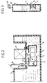
- Figure 3 shows on a smaller scale an alternative embodiment of a water tank associated with a pump according to the invention and hung vertically.
- the steam ironing center comprises an iron 1 equipped with a heating soleplate 2 having holes 3 for steam outlet, a steam generator 4 communicating with said steam holes 3, a tank independent water 5 whose housing 6 has a filling opening 7 closed by a vent plug 8 shown diagrammatically in broken lines, an electric motor pump 9 comprising a casing 10 and a movable internal member 11 for driving the water between an inlet orifice 12 connected to said reservoir and a discharge orifice 13 connected, by a pipe 14 to the steam generator 4, as well as a means 15 for treating the water intended in particular for demineralizing it.
- the steam generator 4 is integrated into the iron 1 and is equipped, in a manner known per se, with a device for drip water flow comprising a small chamber 16 whose outlet 17 is provided with an adjustable needle 18 and whose inlet is connected by the pipe 14 by means 15 of water treatment.
- a device for drip water flow comprising a small chamber 16 whose outlet 17 is provided with an adjustable needle 18 and whose inlet is connected by the pipe 14 by means 15 of water treatment.
- the steam generator 4 could be independent of the iron and installed on the pipe 14 or in the housing 6 of the tank modified for this purpose.
- the pump 9 has a free circulation of water between the two inlet 12 and discharge 13 ports at least when the drive member 11 is at rest.
- the pump 9 is of the centrifugal type and the movable member 11 is constituted by a paddle wheel secured to a drive shaft 19 and rotatably mounted in the casing 10 with at least one peripheral clearance (referenced by e in FIG. 1), said casing 10 having the intake orifice 12 arranged axially, and the discharge orifice 13 arranged at its periphery.
- pumps which are known per se can be used as the pump for free circulation of water in which the drive member, vanes or rollers, rubs against the casing under the effect of centrifugal force when it is in motion, and spares play when it is at rest under the effect of an elastic return.
- the centrifugal pump 9 used is of the vertical type with submerged casing and is mounted for this purpose in a well 20 formed in the housing 6 of the tank 5 with its suction inlet 12 facing towards the bottom of said reservoir.
- the casing 10 is located near the bottom of the tank and is mounted in leaktight manner in the well 20 by means of a peripheral seal 20 '.
- the impeller 11 is always submerged when the tank is filled with water.
- the pump 9 is self-priming, and the casing 10 has for this purpose an additional degassing opening 21 arranged on the upper wall of the casing through which the motor shaft 19 passes.
- the air having accumulated in the casing 10 can escape under the pressure of the water through the opening 21, allowing the impeller 11 to be submerged again.
- the advantages linked to the use of a free circulation pump of the centrifugal type are: reduction of the manufacturing cost of the power station; reliability of the pump due to the absence of valve and spring; practically empty operation of the pump; safety ensured in the event of overpressure of vapor in the pipeline; regular flow of water at the outlet of the pump without harmful pulsation for the needle 18 and the chamber 4, as in the case of an electromagnetic pump.
- the means 15 for treating the water is mounted in the pipe 14 between the steam generator 4 and the pump 9, and comprises a cassette 13 comprising at least one filter 22 arranged at the outlet of water and a demineralization product of water such as a resin.
- the cassette 13 comprises two filters, the filter 22 and a filter 23 arranged at the inlet of the cassette and intended to retain the impurities contained in the water of the tank.
- this cassette 15 is installed in the housing 6.
- the cassette 15, (shown in broken lines), is arranged in said iron iron 1 and is removably mounted, in a manner known per se, to allow its exchange when the resin is saturated. This arrangement allows, in addition to placing the cassette in the iron for a better view of its state of saturation, to install the pump 9 as close as possible to the bottom of the tank 5 so as to facilitate its priming and the pressurization of the circuit. of water.
- the Applicant has overcome a prejudice which prevented it from equipping known irons with a spray nozzle, comprising a so-called "forced” water circulation pump such as an electromagnetic or peristaltic pump.
- the piston spray pump cannot create sufficient vacuum in the line 14 to, at the same time, actuate the valves of the "forced” water circulation pump and overcome the pressure drop of the cassette. demineralization to pump water from the reservoir.
- the vaporization pump 24 by repeated action on the piston 24 ', easily draws water from the reservoir 5 through the cassette 15 and the clearance e existing between the housing 10 and the member 11 of the pump 9.
- the cassette 13 due to its arrangement makes it possible to reduce the pressure of the water in the pipeline and to obtain a particularly advantageous and effective regulation of the water flow for adjusting the flow d in the steam generator at the level of the small chamber 16 and of the needle 18.
- the water pipe 14 connected to the steam generator 4 comprises a valve. 30 whose opening allowing the passage of water is controlled by a thermal element 31 such as a bimetallic strip in connection with the heating sole 2.
- a thermal element 31 such as a bimetallic strip in connection with the heating sole 2.
Landscapes
- Health & Medical Sciences (AREA)
- Public Health (AREA)
- Engineering & Computer Science (AREA)
- Textile Engineering (AREA)
- Irons (AREA)
Applications Claiming Priority (2)
| Application Number | Priority Date | Filing Date | Title |
|---|---|---|---|
| FR9202417 | 1992-02-28 | ||
| FR9202417A FR2688013B1 (fr) | 1992-02-28 | 1992-02-28 | Centrales de repassage a vapeur comprenant un fer a repasser. |
Publications (2)
| Publication Number | Publication Date |
|---|---|
| EP0557901A1 true EP0557901A1 (de) | 1993-09-01 |
| EP0557901B1 EP0557901B1 (de) | 1996-04-17 |
Family
ID=9427206
Family Applications (1)
| Application Number | Title | Priority Date | Filing Date |
|---|---|---|---|
| EP19930102642 Expired - Lifetime EP0557901B1 (de) | 1992-02-28 | 1993-02-19 | Dampfbügelvorrichtung mit zugehörigem Bügeleisen |
Country Status (4)
| Country | Link |
|---|---|
| EP (1) | EP0557901B1 (de) |
| DE (1) | DE69302200T2 (de) |
| ES (1) | ES2086145T3 (de) |
| FR (1) | FR2688013B1 (de) |
Cited By (10)
| Publication number | Priority date | Publication date | Assignee | Title |
|---|---|---|---|---|
| EP0588164A1 (de) * | 1992-09-16 | 1994-03-23 | Moulinex S.A. | Verbindungsvorrichtung für eine in einer Dampfbügeleinrichtung montierte Entmineralisierungsshülse |
| EP0785303A1 (de) * | 1996-01-19 | 1997-07-23 | Seb S.A. | Elektrisches Dampfhaushaltgerät mit einer Antikesselsteinvorrichtung |
| US5842295A (en) * | 1997-06-30 | 1998-12-01 | U. S. Philips Corporation | Ironing machine having an iron and a stand |
| SG55210A1 (en) * | 1996-07-01 | 2005-01-28 | Koninkl Philips Electronics Nv | Ironing machines comprising an iron and a stand |
| EP1616992A1 (de) * | 2004-07-15 | 2006-01-18 | IMETEC S.p.A. | Bügelvorrichtung mit einem Filter |
| US7127839B2 (en) * | 2004-04-01 | 2006-10-31 | Seb S.A. | Iron including an additive reservoir |
| WO2012063168A1 (de) * | 2010-11-12 | 2012-05-18 | BSH Bosch und Siemens Hausgeräte GmbH | Haushaltsgerät, insbesondere dampfbügeleisen |
| GB2506527A (en) * | 2012-09-10 | 2014-04-02 | Mark Richard Jennings | Cordless electric iron with blower |
| ITTO20130256A1 (it) * | 2013-03-28 | 2014-09-29 | Indesit Co Spa | Apparecchio di stiratura, in particolare di uso domestico |
| WO2014155310A3 (en) * | 2013-03-28 | 2014-12-04 | Indesit Company S.P.A. | Ironing appliance, in particular for household use |
Families Citing this family (2)
| Publication number | Priority date | Publication date | Assignee | Title |
|---|---|---|---|---|
| DE10106141B4 (de) * | 2001-02-10 | 2006-12-07 | INTER CONTROL Hermann Köhler Elektrik GmbH & Co KG | Thermisch gesteuerte Einrichtung zur Betätigung einer Ventilöffnung, insbesondere eines Flüssigkeitsventils |
| FR2979924B1 (fr) * | 2011-09-09 | 2013-10-11 | Seb Sa | Appareil electromenager comportant un circuit de distribution de vapeur |
Citations (4)
| Publication number | Priority date | Publication date | Assignee | Title |
|---|---|---|---|---|
| EP0117852A2 (de) * | 1983-03-01 | 1984-09-05 | Cesarina Filippi | Dampfbügelvorrichtung |
| EP0135484A2 (de) * | 1983-07-18 | 1985-03-27 | ELWATT S.r.l. | Dampferzeuger zum Gebrauch bei Haushaltsgeräten, wie etwa Dampfbügeleisen |
| BE904629A (fr) * | 1986-04-18 | 1986-08-18 | Despontin Philippe | Procede de repassage, fer a repasser et dispositif de repassage mettant en oeuvre un tel fer. |
| FR2582028A1 (fr) * | 1985-05-20 | 1986-11-21 | Brenot Claude | Appareil de repassage a evaporation directe |
-
1992
- 1992-02-28 FR FR9202417A patent/FR2688013B1/fr not_active Expired - Fee Related
-
1993
- 1993-02-19 DE DE1993602200 patent/DE69302200T2/de not_active Expired - Fee Related
- 1993-02-19 ES ES93102642T patent/ES2086145T3/es not_active Expired - Lifetime
- 1993-02-19 EP EP19930102642 patent/EP0557901B1/de not_active Expired - Lifetime
Patent Citations (4)
| Publication number | Priority date | Publication date | Assignee | Title |
|---|---|---|---|---|
| EP0117852A2 (de) * | 1983-03-01 | 1984-09-05 | Cesarina Filippi | Dampfbügelvorrichtung |
| EP0135484A2 (de) * | 1983-07-18 | 1985-03-27 | ELWATT S.r.l. | Dampferzeuger zum Gebrauch bei Haushaltsgeräten, wie etwa Dampfbügeleisen |
| FR2582028A1 (fr) * | 1985-05-20 | 1986-11-21 | Brenot Claude | Appareil de repassage a evaporation directe |
| BE904629A (fr) * | 1986-04-18 | 1986-08-18 | Despontin Philippe | Procede de repassage, fer a repasser et dispositif de repassage mettant en oeuvre un tel fer. |
Cited By (15)
| Publication number | Priority date | Publication date | Assignee | Title |
|---|---|---|---|---|
| EP0588164A1 (de) * | 1992-09-16 | 1994-03-23 | Moulinex S.A. | Verbindungsvorrichtung für eine in einer Dampfbügeleinrichtung montierte Entmineralisierungsshülse |
| EP0785303A1 (de) * | 1996-01-19 | 1997-07-23 | Seb S.A. | Elektrisches Dampfhaushaltgerät mit einer Antikesselsteinvorrichtung |
| FR2743823A1 (fr) * | 1996-01-19 | 1997-07-25 | Seb Sa | Appareil electromenager a vapeur comportant un dispositif anti-tartre |
| US5743034A (en) * | 1996-01-19 | 1998-04-28 | Seb S.A. | Household steam appliance having a scale-preventing device |
| SG55210A1 (en) * | 1996-07-01 | 2005-01-28 | Koninkl Philips Electronics Nv | Ironing machines comprising an iron and a stand |
| US5842295A (en) * | 1997-06-30 | 1998-12-01 | U. S. Philips Corporation | Ironing machine having an iron and a stand |
| CN100570044C (zh) * | 2004-04-01 | 2009-12-16 | Seb公司 | 包括一添加剂容器的熨斗 |
| US7127839B2 (en) * | 2004-04-01 | 2006-10-31 | Seb S.A. | Iron including an additive reservoir |
| EP1616992A1 (de) * | 2004-07-15 | 2006-01-18 | IMETEC S.p.A. | Bügelvorrichtung mit einem Filter |
| WO2012063168A1 (de) * | 2010-11-12 | 2012-05-18 | BSH Bosch und Siemens Hausgeräte GmbH | Haushaltsgerät, insbesondere dampfbügeleisen |
| GB2506527A (en) * | 2012-09-10 | 2014-04-02 | Mark Richard Jennings | Cordless electric iron with blower |
| ITTO20130256A1 (it) * | 2013-03-28 | 2014-09-29 | Indesit Co Spa | Apparecchio di stiratura, in particolare di uso domestico |
| WO2014155310A3 (en) * | 2013-03-28 | 2014-12-04 | Indesit Company S.P.A. | Ironing appliance, in particular for household use |
| CN105074079A (zh) * | 2013-03-28 | 2015-11-18 | 英德斯特股份公司 | 熨烫器械,尤其是用于家庭使用 |
| EP3059343A1 (de) * | 2013-03-28 | 2016-08-24 | Indesit Company S.p.A. | Bügelvorrichtung, insbesondere für den haushaltsgebrauch, mit einer siebvorrichtung |
Also Published As
| Publication number | Publication date |
|---|---|
| EP0557901B1 (de) | 1996-04-17 |
| FR2688013B1 (fr) | 1995-11-10 |
| ES2086145T3 (es) | 1996-06-16 |
| DE69302200D1 (de) | 1996-05-23 |
| FR2688013A1 (fr) | 1993-09-03 |
| DE69302200T2 (de) | 1996-08-14 |
Similar Documents
| Publication | Publication Date | Title |
|---|---|---|
| EP0557901B1 (de) | Dampfbügelvorrichtung mit zugehörigem Bügeleisen | |
| CA2159097C (fr) | Systeme de regulation d'air pour reservoir hydropneumatique | |
| FR2720118A1 (fr) | Pompe de carburant à moteur électrique. | |
| FR2698664A1 (fr) | Circuit de distribution de carburant pour moteur à combustion interne. | |
| FR2690932A1 (fr) | Fer à repasser à vapeur. | |
| RU95114955A (ru) | Нагнетающее устройство для относительно летучей жидкости | |
| FR2721539A1 (fr) | Appareil de nettoyage multifonctionnel. | |
| EP0931928A1 (de) | Vorrichtung zum Verhindern von Kavitation bei Einspritzpumpen | |
| FR2933531A1 (fr) | Dispositif de detection de niveau de liquide | |
| US2421237A (en) | Air charger for jet pumps | |
| EP0121456B1 (de) | Tauchpumpe mit Laufrad | |
| US2022624A (en) | Self-priming rotary pump | |
| EP3783145A1 (de) | Elektrohaushaltsgerät, das einen behälter zur dampfdruckerzeugung umfasst | |
| FR2531493A1 (fr) | Systeme d'alimentation en carburant pour un moteur a combustion interne | |
| KR100727786B1 (ko) | 차량용 연료펌프 구조물 및 연료공급장치 | |
| JP2862162B2 (ja) | 衛生洗浄装置 | |
| US1581204A (en) | Self-priming centrifugal pump | |
| EP0852684B1 (de) | Hydropneumatisches schwallschutzreservoir mit einer vorrichtung zur regelbaren luftzufuhr sowie verfahren zur luftzufuhr | |
| FR2928707A1 (fr) | Systeme de succion et piscine ou spa comportant un tel systeme | |
| FR2934878A1 (fr) | Moto pompe a ecoulement axial. | |
| BE437453A (de) | ||
| FR2473643A1 (fr) | Pompe immergee pour grande profondeur | |
| FR2618857A3 (fr) | Turbopompe a chambre de pompe realisee dans un carter de pompe, dans laquelle est dispose un rotor de pompe | |
| EP0041012A1 (de) | Gerät für Getränke mit einer thermischen Pumpe | |
| JPH0953268A (ja) | 止水弁付便座洗浄水噴射用ポンプ |
Legal Events
| Date | Code | Title | Description |
|---|---|---|---|
| PUAI | Public reference made under article 153(3) epc to a published international application that has entered the european phase |
Free format text: ORIGINAL CODE: 0009012 |
|
| AK | Designated contracting states |
Kind code of ref document: A1 Designated state(s): BE DE ES GB IT NL PT |
|
| 17P | Request for examination filed |
Effective date: 19931126 |
|
| 17Q | First examination report despatched |
Effective date: 19951004 |
|
| GRAH | Despatch of communication of intention to grant a patent |
Free format text: ORIGINAL CODE: EPIDOS IGRA |
|
| GRAA | (expected) grant |
Free format text: ORIGINAL CODE: 0009210 |
|
| AK | Designated contracting states |
Kind code of ref document: B1 Designated state(s): BE DE ES GB IT NL PT |
|
| GBT | Gb: translation of ep patent filed (gb section 77(6)(a)/1977) |
Effective date: 19960423 |
|
| REF | Corresponds to: |
Ref document number: 69302200 Country of ref document: DE Date of ref document: 19960523 |
|
| REG | Reference to a national code |
Ref country code: ES Ref legal event code: FG2A Ref document number: 2086145 Country of ref document: ES Kind code of ref document: T3 |
|
| ITF | It: translation for a ep patent filed |
Owner name: FUMERO BREVETTI S.N.C. |
|
| SC4A | Pt: translation is available |
Free format text: 960521 AVAILABILITY OF NATIONAL TRANSLATION |
|
| PLBE | No opposition filed within time limit |
Free format text: ORIGINAL CODE: 0009261 |
|
| STAA | Information on the status of an ep patent application or granted ep patent |
Free format text: STATUS: NO OPPOSITION FILED WITHIN TIME LIMIT |
|
| 26N | No opposition filed | ||
| PGFP | Annual fee paid to national office [announced via postgrant information from national office to epo] |
Ref country code: PT Payment date: 20001221 Year of fee payment: 9 |
|
| REG | Reference to a national code |
Ref country code: PT Ref legal event code: NF4A Free format text: 'RESTITUTIO IN INTEGRUM' Effective date: 20000929 |
|
| PGFP | Annual fee paid to national office [announced via postgrant information from national office to epo] |
Ref country code: NL Payment date: 20010228 Year of fee payment: 9 |
|
| PGFP | Annual fee paid to national office [announced via postgrant information from national office to epo] |
Ref country code: BE Payment date: 20010403 Year of fee payment: 9 |
|
| REG | Reference to a national code |
Ref country code: GB Ref legal event code: IF02 |
|
| PGFP | Annual fee paid to national office [announced via postgrant information from national office to epo] |
Ref country code: ES Payment date: 20020211 Year of fee payment: 10 |
|
| PGFP | Annual fee paid to national office [announced via postgrant information from national office to epo] |
Ref country code: GB Payment date: 20020219 Year of fee payment: 10 |
|
| PG25 | Lapsed in a contracting state [announced via postgrant information from national office to epo] |
Ref country code: BE Free format text: LAPSE BECAUSE OF NON-PAYMENT OF DUE FEES Effective date: 20020228 |
|
| PGFP | Annual fee paid to national office [announced via postgrant information from national office to epo] |
Ref country code: DE Payment date: 20020301 Year of fee payment: 10 |
|
| BERE | Be: lapsed |
Owner name: S.A. MOULINEX Effective date: 20020228 |
|
| PG25 | Lapsed in a contracting state [announced via postgrant information from national office to epo] |
Ref country code: PT Free format text: LAPSE BECAUSE OF NON-PAYMENT OF DUE FEES Effective date: 20020831 |
|
| PG25 | Lapsed in a contracting state [announced via postgrant information from national office to epo] |
Ref country code: NL Free format text: LAPSE BECAUSE OF NON-PAYMENT OF DUE FEES Effective date: 20020901 |
|
| NLV4 | Nl: lapsed or anulled due to non-payment of the annual fee |
Effective date: 20020901 |
|
| REG | Reference to a national code |
Ref country code: PT Ref legal event code: MM4A Free format text: LAPSE DUE TO NON-PAYMENT OF FEES Effective date: 20020831 |
|
| PG25 | Lapsed in a contracting state [announced via postgrant information from national office to epo] |
Ref country code: GB Free format text: LAPSE BECAUSE OF NON-PAYMENT OF DUE FEES Effective date: 20030219 |
|
| PG25 | Lapsed in a contracting state [announced via postgrant information from national office to epo] |
Ref country code: ES Free format text: LAPSE BECAUSE OF NON-PAYMENT OF DUE FEES Effective date: 20030220 |
|
| PG25 | Lapsed in a contracting state [announced via postgrant information from national office to epo] |
Ref country code: DE Free format text: LAPSE BECAUSE OF NON-PAYMENT OF DUE FEES Effective date: 20030902 |
|
| GBPC | Gb: european patent ceased through non-payment of renewal fee | ||
| REG | Reference to a national code |
Ref country code: ES Ref legal event code: FD2A Effective date: 20030220 |
|
| PG25 | Lapsed in a contracting state [announced via postgrant information from national office to epo] |
Ref country code: IT Free format text: LAPSE BECAUSE OF NON-PAYMENT OF DUE FEES;WARNING: LAPSES OF ITALIAN PATENTS WITH EFFECTIVE DATE BEFORE 2007 MAY HAVE OCCURRED AT ANY TIME BEFORE 2007. THE CORRECT EFFECTIVE DATE MAY BE DIFFERENT FROM THE ONE RECORDED. Effective date: 20050219 |