EP0557791B1 - Filtervorrichtung, insbesondere für Dispersionsfarben - Google Patents
Filtervorrichtung, insbesondere für Dispersionsfarben Download PDFInfo
- Publication number
- EP0557791B1 EP0557791B1 EP93102022A EP93102022A EP0557791B1 EP 0557791 B1 EP0557791 B1 EP 0557791B1 EP 93102022 A EP93102022 A EP 93102022A EP 93102022 A EP93102022 A EP 93102022A EP 0557791 B1 EP0557791 B1 EP 0557791B1
- Authority
- EP
- European Patent Office
- Prior art keywords
- vessel
- filter device
- filter
- sieving
- container
- Prior art date
- Legal status (The legal status is an assumption and is not a legal conclusion. Google has not performed a legal analysis and makes no representation as to the accuracy of the status listed.)
- Expired - Lifetime
Links
- 239000003973 paint Substances 0.000 title claims abstract description 6
- 239000006185 dispersion Substances 0.000 title claims abstract 4
- 239000000706 filtrate Substances 0.000 claims abstract description 17
- 239000000463 material Substances 0.000 claims abstract description 7
- 230000033001 locomotion Effects 0.000 claims description 11
- 239000007788 liquid Substances 0.000 claims description 10
- 229910000831 Steel Inorganic materials 0.000 claims description 3
- 239000010959 steel Substances 0.000 claims description 3
- 238000007873 sieving Methods 0.000 claims 12
- 238000004140 cleaning Methods 0.000 abstract description 5
- 239000012535 impurity Substances 0.000 abstract 1
- 239000002826 coolant Substances 0.000 description 9
- 239000000356 contaminant Substances 0.000 description 3
- 239000004809 Teflon Substances 0.000 description 2
- 229920006362 Teflon® Polymers 0.000 description 2
- 230000001133 acceleration Effects 0.000 description 2
- 238000006073 displacement reaction Methods 0.000 description 2
- 239000012065 filter cake Substances 0.000 description 2
- 239000002184 metal Substances 0.000 description 2
- 239000004033 plastic Substances 0.000 description 2
- 229920003023 plastic Polymers 0.000 description 2
- 239000003351 stiffener Substances 0.000 description 2
- 239000004698 Polyethylene Substances 0.000 description 1
- 239000006096 absorbing agent Substances 0.000 description 1
- 230000005540 biological transmission Effects 0.000 description 1
- 239000000872 buffer Substances 0.000 description 1
- 238000013016 damping Methods 0.000 description 1
- 230000007423 decrease Effects 0.000 description 1
- 239000013013 elastic material Substances 0.000 description 1
- 239000000839 emulsion Substances 0.000 description 1
- 239000004744 fabric Substances 0.000 description 1
- 238000001914 filtration Methods 0.000 description 1
- 230000010355 oscillation Effects 0.000 description 1
- 239000002245 particle Substances 0.000 description 1
- 230000002093 peripheral effect Effects 0.000 description 1
- -1 polyethylene Polymers 0.000 description 1
- 229920000573 polyethylene Polymers 0.000 description 1
- 230000035939 shock Effects 0.000 description 1
- 229910001220 stainless steel Inorganic materials 0.000 description 1
- 239000010935 stainless steel Substances 0.000 description 1
- 239000000126 substance Substances 0.000 description 1
Images


Classifications
-
- B—PERFORMING OPERATIONS; TRANSPORTING
- B01—PHYSICAL OR CHEMICAL PROCESSES OR APPARATUS IN GENERAL
- B01D—SEPARATION
- B01D33/00—Filters with filtering elements which move during the filtering operation
- B01D33/01—Filters with filtering elements which move during the filtering operation with translationally moving filtering elements, e.g. pistons
- B01D33/03—Filters with filtering elements which move during the filtering operation with translationally moving filtering elements, e.g. pistons with vibrating filter elements
- B01D33/0307—Filters with filtering elements which move during the filtering operation with translationally moving filtering elements, e.g. pistons with vibrating filter elements with bag, cage, hose, tube, sleeve or the like filtering elements
- B01D33/0315—Filters with filtering elements which move during the filtering operation with translationally moving filtering elements, e.g. pistons with vibrating filter elements with bag, cage, hose, tube, sleeve or the like filtering elements arranged for inward flow filtration
-
- B—PERFORMING OPERATIONS; TRANSPORTING
- B01—PHYSICAL OR CHEMICAL PROCESSES OR APPARATUS IN GENERAL
- B01D—SEPARATION
- B01D33/00—Filters with filtering elements which move during the filtering operation
- B01D33/29—Filters with filtering elements which move during the filtering operation the movement of the filter elements being a combination of movements
-
- B—PERFORMING OPERATIONS; TRANSPORTING
- B01—PHYSICAL OR CHEMICAL PROCESSES OR APPARATUS IN GENERAL
- B01D—SEPARATION
- B01D33/00—Filters with filtering elements which move during the filtering operation
- B01D33/70—Filters with filtering elements which move during the filtering operation having feed or discharge devices
- B01D33/74—Filters with filtering elements which move during the filtering operation having feed or discharge devices for discharging filtrate
- B01D33/742—Filters with filtering elements which move during the filtering operation having feed or discharge devices for discharging filtrate containing fixed liquid displacement elements or cores
-
- B—PERFORMING OPERATIONS; TRANSPORTING
- B01—PHYSICAL OR CHEMICAL PROCESSES OR APPARATUS IN GENERAL
- B01D—SEPARATION
- B01D33/00—Filters with filtering elements which move during the filtering operation
- B01D33/80—Accessories
- B01D33/804—Accessories integrally combined with devices for controlling the filtration
- B01D33/807—Accessories integrally combined with devices for controlling the filtration by level measuring
-
- B—PERFORMING OPERATIONS; TRANSPORTING
- B01—PHYSICAL OR CHEMICAL PROCESSES OR APPARATUS IN GENERAL
- B01D—SEPARATION
- B01D2201/00—Details relating to filtering apparatus
- B01D2201/02—Filtering elements having a conical form
Definitions
- the invention relates to a filter device, in particular for emulsion paints, comprising an essentially pot-shaped container, the central axis of which is arranged vertically, a sieve body projecting into the free liquid level of the filter material with laterally arranged filter surfaces, which at an angle in the interior of the container about its vertically arranged longitudinal axis is reversibly pivotable by less than 360 °, an inlet for filter material opening into the space between the inside of the container wall and the outside of the sieve body and a filtrate outlet introduced from above into the interior of the sieve body, which opens below the liquid level of the filtrate,
- Such a filter device is known from US-A-4,028,247 as a filter system for treating the coolant of a machine tool.
- the sieve body is fastened in a bush which is rotatably mounted around the connecting piece of the coolant supply line.
- the connector of the coolant supply line projects vertically through the free liquid level into the coolant reservoir.
- the coolant flows through the screen body from the outside inwards and is removed from the coolant reservoir through the connection piece of the coolant supply line located in the center of the screen body.
- a reversing rotary movement of the sieve body is intended to remove metal chips and contaminants that accumulate on the outside of the sieve body.
- a driver with a guide wheel is arranged in the upper area of the bush carrying the screen body, which is set in a reversing rotary movement by a continuously rotating cam disk and transmits this to the screen body.
- the guide wheel of the driver is pressed against the cam disk by the spring force of a return spring.
- the shaft of the cam disc is rotatably mounted in a housing attached to the coolant supply line.
- the cam disc has the shape of an equilateral triangle with rounded corners, so that three oscillating movements occur per revolution.
- the reversing rotary motion of the screen body therefore represents a sinusoidal oscillation in its path, speed and acceleration behavior, the acceleration of which gradually decreases when a reversal point is reached, assumes the value zero for a minimal point in time at the reversal point and then gradually increases again with a changed direction sign.
- the inertial forces generated by the mechanics described above are just sufficient.
- a self-cleaning pressure or vacuum filter is known, to which the cloudy liquid to be filtered is fed through an inlet in a pressure-resistant container.
- the cloudy liquid passes through a horizontal filter plate located in the lower area of the container, which consists of a lower plate, a support structure carrying the filter medium and the filter medium.
- the cloudy particles are absorbed by the filter medium during the passage of the filter medium and the filtrate leaves the interior of the filter plate via a flexible connecting line and a shut-off device.
- the filter plate is rotated back and forth in a circular motion.
- the filter cake thrown off by centrifugal force passes through an annular gap between the filter plate and the container wall into the lower region of the container, from which it can be removed from the apparatus via a drain valve.
- the object of the present invention is to provide a filter device for the continuous removal of contaminants from liquids by a combination of large inertial forces and strong eddies in the Liquid layers surrounding the filter body without creating a mechanical cleaning system touching the filter body.
- this object is achieved in that the container is closed in a pressure-tight manner by a lid, that the sieve body is fastened to a shaft pivotably mounted in the center of the shaft, that a stop element is provided on the shaft to limit the pivoting movement, and a counter-stop element is provided on the lid, that the filtrate drain is firmly connected to the container and is guided parallel to the longitudinal axis of the container in the container, and that the container has a drain for filter residues in its lower region.
- the screen body is pivoted back and forth about 60 times per minute.
- the peripheral speed of the screen body should be about 0.2 - 0.4 m ⁇ s ⁇ 1. It is recommended to pivot the sieve body through an angle in the range from 45 ° to 120 °, preferably from 80 °. Because of this constant self-cleaning of the sieve body, the filtrate passes through the sieve body almost without pressure, so that the difference in the liquid level outside the sieve body compared to the liquid level of the filtrate is very small.
- the shaft carrying the sieve body can be supported in the cover, for example, by two spaced-apart ball bearings.
- a pneumatic, electric or hydraulic drive can be provided as the reversing drive device, which is connected to the shaft either directly or with the interposition of transmission elements such as chain drive or gear wheels.
- the intensive removal of the filter residue from the sieve surface is achieved in that a stop element is provided on the shaft and a counter stop element on the cover of the container to limit the pivoting movement.
- the mutually abutting surfaces are advantageously covered with an elastic material which acts as a shock absorber with a damping angle of 2 ° to 5 ° rotation angle.
- a sector at least corresponding to the angle of the pivoting movement on the top of the filter body is open, so that when the filter body becomes blocked, uncleaned filter material enters the interior of the filter body could occur.
- a level sensor is provided on the container below the upper edge of the sieve body.
- a capacitive proximity switch is preferably used as the level sensor, which is attached to the outside of the container behind a plastic window.
- the supply of filter residue to the drain in the bottom of the container is facilitated if the container and the sieve body are conical in the bottom region with the tip pointing downward.
- the cone angle should be about 90 °.
- the sinking of filter residue is facilitated if the filter body is conical in the area of its side wall with an increasing diameter.
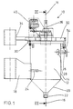
- FIG. 1 shows a filter device 10 according to the invention in a side view.
- a container 12 with a 375 mm high cylindrical side wall 14 with a diameter of 300 mm is fastened with a vertically extending central axis 16 in a frame made of square tubes, not shown here, by means of a container holder 18.
- the bottom region 20 of the container 12 is conical in shape with a cone angle of 90 ° with the tip pointing downward and is provided in the region of its tip with an outlet 22 for filter residue consisting of a 1.25 "tube.
- a tangential inlet 24 consisting of a 0.5 "tube is provided for filter material.
- the filter device 10 is suitable for a throughput of 9 l ⁇ min ⁇ 1, the flow rate in the inlet 24 is 0.75 m ⁇ s ⁇ 1.
- a fill level sensor 26 which is responsive to capacitive changes and which is arranged directly on a plastic window 28 made of low-pressure polyethylene in the side wall 14.
- annular flange 30 is provided, on which a lid 32 is placed.
- the container 12 is made of V2A steel coated with Teflon and is designed for an overpressure of 3 bar.
- the lid 32 is guided in the same frame as the container 12 in the direction of the central axis 16 by means of a lid holder 34.
- the cover 32 is penetrated by a 200 mm long shaft 36 mounted in it, which is connected via a chain drive 38 to a pneumatically operated drive device 40.
- FIG. 2 shows a top view of the filter device, in particular the upper side of the cover 32.
- a total of six stiffeners 42, 44, 46, 48, 50, 52 are provided on the upper side of the cover 32 with a diameter of 350 mm , at the ends of which a clamping element 54 is provided.
- a filtrate drain 56 consisting of a 0.5 "tube is arranged parallel to the central axis 16.
- the filtrate drain 56 is bent on the underside of the cover 32 towards the central axis 16 and ends at a distance of 260 mm from the cover 32
- a manometer 58 is arranged diametrically opposite the filtrate outlet 56.
- a shaft-sector-shaped stop element 60 is connected in a rotationally fixed manner to the shaft 36 and can act on a ring-sector-shaped counter-stop element 62 which is also connected to the cover 32.
- elastic buffers 64, 66 are arranged, which brake the swiveling movement and cause the pneumatic drive device 40 to reverse the direction.
- FIG. 3 which shows the filter device 10 in longitudinal section along the line III-III in FIG. 1 or FIG. 2, shows the arrangement of a sieve body 68 in the interior 70 of the container 12.
- the screen body 68 is approximately flower pot-shaped and with a conical base area 72 with a downward-pointing tip with a cone angle of 120 °.
- the sieve body is conical with a diameter increasing from 180 mm up to 255 mm.
- the screen body 68 has an annular flange 76 with an outer diameter of 255 mm, an inner diameter of 195 mm and a height of 10 mm, which is connected to the shaft 36 by means of a fastening element 78.
- the shaft 36 is pivotally mounted in a socket 80, which is arranged concentrically to the central axis 16 in the center of the cover 32 and has an inner diameter of 68 mm and a length of 72 mm, by means of two ball bearings 82, 84 spaced apart from one another in the axial direction. In the area of the bearing, the shaft 36 has an outer diameter of 40 mm.
- a cylindrical displacement body 88 coated with Teflon In the interior 86 of the screen body 68 there is a cylindrical displacement body 88 coated with Teflon and having a diameter of 130 mm and a height of 296 mm. The displacement body 88 essentially serves to reduce the volume content of the filter device.
- FIG. 4 shows the screen body 68 in longitudinal section, a screen fabric 90 is shown schematically, which has square meshes of 0.2 mm width.
- the screen mesh consists of stainless steel wires with a diameter of 0.125 mm. The wires run at an angle of 45 ° to the central axis 16.
- FIG. 5 shows a top view of the screen body 68, in particular the fastening element 78.
- a cutout 92 in the form of an annular ring is provided, which enables the filtrate outlet 56 to pass through.
Landscapes
- Chemical & Material Sciences (AREA)
- Chemical Kinetics & Catalysis (AREA)
- Filtration Of Liquid (AREA)
- Paints Or Removers (AREA)
Applications Claiming Priority (2)
| Application Number | Priority Date | Filing Date | Title |
|---|---|---|---|
| DE4204613 | 1992-02-15 | ||
| DE4204613A DE4204613C1 (enExample) | 1992-02-15 | 1992-02-15 |
Publications (2)
| Publication Number | Publication Date |
|---|---|
| EP0557791A1 EP0557791A1 (de) | 1993-09-01 |
| EP0557791B1 true EP0557791B1 (de) | 1995-05-31 |
Family
ID=6451836
Family Applications (1)
| Application Number | Title | Priority Date | Filing Date |
|---|---|---|---|
| EP93102022A Expired - Lifetime EP0557791B1 (de) | 1992-02-15 | 1993-02-10 | Filtervorrichtung, insbesondere für Dispersionsfarben |
Country Status (3)
| Country | Link |
|---|---|
| EP (1) | EP0557791B1 (enExample) |
| AT (1) | ATE123236T1 (enExample) |
| DE (1) | DE4204613C1 (enExample) |
Families Citing this family (5)
| Publication number | Priority date | Publication date | Assignee | Title |
|---|---|---|---|---|
| RU2133135C1 (ru) * | 1998-02-16 | 1999-07-20 | Волгоградский государственный технический университет | Фильтр для разделения суспензий |
| CN103949106B (zh) * | 2014-04-25 | 2016-01-27 | 安徽博泰氟材料科技有限公司 | 一种新型的油漆过滤除杂装置 |
| CN113058317B (zh) * | 2021-03-16 | 2023-10-27 | 河南汉永农业发展有限公司 | 一种淀粉自动搅拌过滤装置 |
| CN112973246B (zh) * | 2021-03-26 | 2022-08-05 | 重庆电力高等专科学校 | 渗滤液排污过滤装置 |
| CN117023915B (zh) * | 2023-10-07 | 2024-01-09 | 山东华盛创新纺织科技有限公司 | 一种纺织污水处理装置 |
Family Cites Families (4)
| Publication number | Priority date | Publication date | Assignee | Title |
|---|---|---|---|---|
| DE1461427A1 (de) * | 1964-11-24 | 1968-12-19 | Buerde Dr Ing Hans | Selbstreinigendes Druck- bzw. Vakuumfilter ohne bewegte Dichtungen |
| DE2043845A1 (en) * | 1970-09-04 | 1972-03-09 | Flach, Rolf, 7031 Gärtringen | Rapid water purifier - using rotating drum filter |
| CH569505A5 (enExample) * | 1973-10-23 | 1975-11-28 | Kaspar Jan | |
| US4028247A (en) * | 1975-07-07 | 1977-06-07 | Yessaian Harry A | Vibratory coolant strainer for machine tool coolant systems |
-
1992
- 1992-02-15 DE DE4204613A patent/DE4204613C1/de not_active Expired - Fee Related
-
1993
- 1993-02-10 AT AT93102022T patent/ATE123236T1/de not_active IP Right Cessation
- 1993-02-10 EP EP93102022A patent/EP0557791B1/de not_active Expired - Lifetime
Also Published As
| Publication number | Publication date |
|---|---|
| DE4204613C1 (enExample) | 1993-03-11 |
| ATE123236T1 (de) | 1995-06-15 |
| EP0557791A1 (de) | 1993-09-01 |
Similar Documents
| Publication | Publication Date | Title |
|---|---|---|
| DE3920097C2 (de) | Vorrichtung zur Filtration von mit Partikeln belasteten Flüssigkeiten | |
| DE69407037T2 (de) | Rotierender filter | |
| DE4423439A1 (de) | Pneumatisch arbeitende Vorrichtung zur Filterreinigung | |
| DE3733306C1 (de) | Rueckspuelfilter | |
| DE4118423C2 (enExample) | ||
| EP2185262B1 (de) | Druckfilter mit vibrationsantrieb | |
| EP3621717A1 (de) | Filtervorrichtung | |
| EP0557791B1 (de) | Filtervorrichtung, insbesondere für Dispersionsfarben | |
| DE3218109A1 (de) | Verfahren und vorrichtung zum herausfiltern von schmutzteilchen aus einem fluessigkeits-teilchen-gemisch | |
| EP0672459B1 (de) | Filterzentrifuge | |
| EP0925147A1 (de) | Brillenglasrandschleifmaschine | |
| DE3608957A1 (de) | Brillenglasrandschleifmaschine | |
| DE2657354C2 (de) | Reinigungseinrichtung für einen Getränkezubereitungsbehälter | |
| EP2468380A1 (de) | Filtervorrichtung | |
| DE2629958A1 (de) | Filtriervorrichtung zum filtrieren von schlammigen fluessigkeiten | |
| DE19547085A1 (de) | Poliermaschine | |
| DE1915561C3 (de) | Rotierende Filtertrommel zur Konzentration verdünnter Fasersuspensionen | |
| DE3433572C2 (enExample) | ||
| DE10248638A1 (de) | Abscheidevorrichtung, insbesondere zur Abscheidung von Feststoffen aus Flüssigkeiten | |
| DE19501896A1 (de) | Kantenspaltfilter für Flüssigkeiten | |
| DE3342689A1 (de) | Filtervorrichtung zum entfernen von verunreinigungen aus fluessigkeiten, insbesondere aus dispersionsfarben | |
| DE3838871C2 (de) | Windsichter | |
| EP0650753B2 (de) | Rückspülbare Filtereinrichtung | |
| DE2154713A1 (de) | Siebanordnung an ruehrwerksmuehlen | |
| DE4337187C1 (de) | Rückspülbare Filtereinrichtung |
Legal Events
| Date | Code | Title | Description |
|---|---|---|---|
| PUAI | Public reference made under article 153(3) epc to a published international application that has entered the european phase |
Free format text: ORIGINAL CODE: 0009012 |
|
| AK | Designated contracting states |
Kind code of ref document: A1 Designated state(s): AT BE CH DE DK ES FR GB GR IE IT LI LU MC NL PT SE |
|
| RBV | Designated contracting states (corrected) |
Designated state(s): AT FR GB IT NL |
|
| RAP1 | Party data changed (applicant data changed or rights of an application transferred) |
Owner name: BRAAS GMBH |
|
| REG | Reference to a national code |
Ref country code: DE Ref legal event code: 8566 |
|
| 17P | Request for examination filed |
Effective date: 19940215 |
|
| 17Q | First examination report despatched |
Effective date: 19940606 |
|
| GRAA | (expected) grant |
Free format text: ORIGINAL CODE: 0009210 |
|
| AK | Designated contracting states |
Kind code of ref document: B1 Designated state(s): AT FR GB IT NL |
|
| PG25 | Lapsed in a contracting state [announced via postgrant information from national office to epo] |
Ref country code: FR Effective date: 19950531 |
|
| REF | Corresponds to: |
Ref document number: 123236 Country of ref document: AT Date of ref document: 19950615 Kind code of ref document: T |
|
| ITF | It: translation for a ep patent filed | ||
| GBT | Gb: translation of ep patent filed (gb section 77(6)(a)/1977) |
Effective date: 19950915 |
|
| EN | Fr: translation not filed | ||
| PLBE | No opposition filed within time limit |
Free format text: ORIGINAL CODE: 0009261 |
|
| STAA | Information on the status of an ep patent application or granted ep patent |
Free format text: STATUS: NO OPPOSITION FILED WITHIN TIME LIMIT |
|
| 26N | No opposition filed | ||
| PGFP | Annual fee paid to national office [announced via postgrant information from national office to epo] |
Ref country code: GB Payment date: 19991222 Year of fee payment: 8 |
|
| PGFP | Annual fee paid to national office [announced via postgrant information from national office to epo] |
Ref country code: AT Payment date: 20000214 Year of fee payment: 8 |
|
| PGFP | Annual fee paid to national office [announced via postgrant information from national office to epo] |
Ref country code: NL Payment date: 20000215 Year of fee payment: 8 |
|
| PG25 | Lapsed in a contracting state [announced via postgrant information from national office to epo] |
Ref country code: GB Free format text: LAPSE BECAUSE OF NON-PAYMENT OF DUE FEES Effective date: 20010210 Ref country code: AT Free format text: LAPSE BECAUSE OF NON-PAYMENT OF DUE FEES Effective date: 20010210 |
|
| PG25 | Lapsed in a contracting state [announced via postgrant information from national office to epo] |
Ref country code: NL Free format text: LAPSE BECAUSE OF NON-PAYMENT OF DUE FEES Effective date: 20010901 |
|
| GBPC | Gb: european patent ceased through non-payment of renewal fee |
Effective date: 20010210 |
|
| NLV4 | Nl: lapsed or anulled due to non-payment of the annual fee |
Effective date: 20010901 |
|
| PG25 | Lapsed in a contracting state [announced via postgrant information from national office to epo] |
Ref country code: IT Free format text: LAPSE BECAUSE OF NON-PAYMENT OF DUE FEES;WARNING: LAPSES OF ITALIAN PATENTS WITH EFFECTIVE DATE BEFORE 2007 MAY HAVE OCCURRED AT ANY TIME BEFORE 2007. THE CORRECT EFFECTIVE DATE MAY BE DIFFERENT FROM THE ONE RECORDED. Effective date: 20050210 |