EP0557560A1 - Centrifugeuse à tamis pour la séparation discontinue de mélanges solides-liquides - Google Patents
Centrifugeuse à tamis pour la séparation discontinue de mélanges solides-liquides Download PDFInfo
- Publication number
- EP0557560A1 EP0557560A1 EP92103409A EP92103409A EP0557560A1 EP 0557560 A1 EP0557560 A1 EP 0557560A1 EP 92103409 A EP92103409 A EP 92103409A EP 92103409 A EP92103409 A EP 92103409A EP 0557560 A1 EP0557560 A1 EP 0557560A1
- Authority
- EP
- European Patent Office
- Prior art keywords
- drum
- closure elements
- plates
- held
- star
- Prior art date
- Legal status (The legal status is an assumption and is not a legal conclusion. Google has not performed a legal analysis and makes no representation as to the accuracy of the status listed.)
- Withdrawn
Links
Images


Classifications
-
- B—PERFORMING OPERATIONS; TRANSPORTING
- B04—CENTRIFUGAL APPARATUS OR MACHINES FOR CARRYING-OUT PHYSICAL OR CHEMICAL PROCESSES
- B04B—CENTRIFUGES
- B04B11/00—Feeding, charging, or discharging bowls
- B04B11/04—Periodical feeding or discharging; Control arrangements therefor
- B04B11/05—Base discharge
Definitions
- the invention relates to a screen centrifuge for the batchwise separation of liquid-solid mixtures, in particular a sugar centrifuge, with a drum which has a cylindrical peripheral wall and a lid fastened thereon with a central opening for filling and for the passage of a drive shaft, and in the region of its bottom is connected via an arm star to a hub which is held on the drive shaft in a rotationally secure manner, and has means for discharging the liquid and for emptying the solids from the bottom, a valve device with movably held plate-shaped closure elements and an actuating device for transferring the closure elements into the closed and open positions.
- the solid When the liquid-solid mixture is centrifuged, the solid is distributed on the inside of the peripheral wall of the drum, over its height in a largely constant layer thickness, so that it practically forms a hollow cylinder.
- the solids are discharged after centrifugation in the known drums by a so-called bottom discharge.
- openings provided with closure elements are arranged in the bottom of the drum between the drum hub and the inside diameter of the solid layer.
- the known centrifuges are equipped with a mechanical scraper, which engages in the solid layer at low speed of the drum, possibly also after reversing the direction of rotation in the manner of a plow, and is moved in the engaged position from top to bottom along the inner wall of the drum.
- US Pat. No. 3,773,253 shows a screen centrifuge of the type described in the introduction, in which the closure elements in the form of swivel plates are attached in a hinge-like manner to radial struts which extend from the outer, annularly closed part of the base to the drum hub.
- a height-adjustable rotary coupling is provided centrally below the hub, via which the closure flaps are transferred into the open position after the direction of rotation has been reversed and into the closed position when the drum is driven in the centrifugal direction become.
- the solids are fed to the bottom openings by means of a mechanical scraper, as has already been described above.
- So-called steep-cone drums have been developed in order to avoid the very great effort involved in emptying the centrifuge, in particular through the necessary clearer with the associated actuating devices.
- These consist of a cylindrical drum shell, which is limited at the top by a lid of the type described above and at the lower end of which a cone is connected, the end of which has a smaller diameter and extends to a liftable or lowerable annular base plate, which on the Drum hub is held.
- the invention has for its object to develop a screen centrifuge of the type mentioned in the introduction so that a self-emptying is possible even without a scraper.
- the screen centrifuge is characterized by the features mentioned at the outset in that the plate-shaped closure elements form the peripheral region of the bottom of the drum in the closed position and, in the open position, release an annular opening which extends from the peripheral wall of the drum to at least the thickness of the solid layer .
- the plate-shaped closure elements prevent the filled filling material from escaping during filling and in this way ensure the formation of a constant layer thickness of the filling material or the solids over the drum height. They also absorb the liquid pressure that acts axially on the bottom of the drum during centrifugation. After centrifugation has ended, the closure elements release the peripheral region of the bottom from the inside of the drum peripheral wall to the thickness of the solid layer, so that through this ring opening the solid can fall out of the drum itself without further external action when the drum is at a standstill.
- the plate-shaped closure elements can be designed and arranged so that they are both in the closed and in the open position form the entire drum base between the inside of the peripheral wall of the drum and the drum hub. Without additional internals inside the drum, however, in the open position of the closure elements, part of the solid to be discharged could reach the closure elements when the centrifuge is emptied.
- a cover cone extending into the interior of the drum is provided above the plate-shaped closure elements, the tapered end of which is held on the drive shaft and the end of the large diameter forms the inner boundary of the ring opening that can be released by the closure elements.
- the bottom end of the circumferential wall of the drum is connected to a circumferential ring corresponding to the drum diameter, which practically forms an outer hub of the drum and to which the outwardly pointing arms of the arm star, which are designed as ribs, are fastened .
- the ribs of the arm star have an angled portion or angled portion pointing into the inside of the drum and the hub is arranged within the cover cone.
- this actuating device is below or at least partially within the cover cone is arranged. If the actuating device at least partially protrudes into the cover cone, this contributes to reducing the height of the centrifuge.
- the plate-shaped closure elements can be designed as swiveling plates which can be displaced parallel to themselves in their plane or as swivel plates attached to hinges.
- the closure elements are designed as slide plates which are supported by the ribs of the arm star and overlap in the closed position, and that a common piston-cylinder arrangement is assigned to all of the plates as an actuating device, which is held centrally with the drum underneath the drum hub and is connected to the plates with a linkage.
- the pressure medium can be supplied to the piston-cylinder arrangement rotating with the drum in a known manner via a rotary transducer.
- the slide plates of the aforementioned first embodiment can be connected to carriages, which in turn are guided on slide rails arranged in a star shape in the lower region and within the cover cone and are connected to the piston-cylinder arrangement via likewise star-shaped handlebar rods.
- the slide plates which also overlap in the closed position on the outer edge regions, can be transferred from the open position to the closed position and back with extremely little force in the plane in which they extend, due to the described design of the centrifuge.
- the closure elements are designed as plates arranged above the arm star, which also overlap in the closed position, that the plates are each held by a parallelogram linkage on the arms of the arm star and the parallelogram frames are arranged with star-shaped handlebars with all of them Plates assigned in the center below the drum hub and connected to this circumferential piston-cylinder arrangement, the outer ends of the arms of the arm star having upwardly pointing shoulders on which the plate-shaped closure elements are supported in the closed position.
- parallelogram linkages are in turn connected to the plate-shaped closure elements, which are arranged within the cover cone in connection with a plurality of piston-cylinder arrangements arranged above the cover cone, the piston rods of which project into the cover cone.
- the arrangement of the piston-cylinder arrangements above the cover cone means that the entire actuating device for the plate-shaped closure elements is inside the centrifuge. In this configuration, the plate-shaped closure elements can rest on the arms of the arm star in the closed position and are thereby securely supported in this position.
- the swivel plates can in turn be actuated by means of a piston-cylinder arrangement provided underneath the drum hub and rotating with the drum hub, as has already been described in connection with the slide plates.
- the plates held radially pivotably in the manner of an aperture lock can be moved into the closed and open position by means of a common piston-cylinder arrangement.
- the plate-shaped closure elements are or are arranged in such a way that they are forced into the closed position during the centrifuging process by the action of the centrifugal force.
- the piston-cylinder arrangements provided for the actuation of the plate-shaped closure elements are expediently designed so that their force is not sufficient to overcome the flying force acting on the plates during the centrifuging process. This ensures that the plates are only moved to the open position and the openings are released for emptying only when the centrifuge is braked shortly before it stops.
- the drawing shows some embodiments of the invention in a schematic representation.
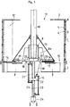
- the drums of the centrifuges are designed to match. They have a cylindrical peripheral wall 3, which is followed by a cover 2, which in the examples shown is designed in the manner of a flat ring, which in each case forms a right angle with the peripheral wall 3.
- the cover 2 can also be designed in the manner of a conical ring which forms an angle of more than 90 ° with the peripheral wall 3.
- the cylindrical drum wall 3 On the inside of the drum wall 3 there is a support screen 4 resting on the wall and a separating screen 5 resting thereon.
- the cylindrical drum wall 3 is equipped with drain holes 6 for the liquid to be flung off, which are distributed over its entire height and also over its circumference.
- the end 1 facing away from the cover 2 is firmly connected to a circumferential ring 7 which is adapted to the inside diameter of the circumferential wall including the sieves 4 and 5.
- This circumferential ring 7 forms the outer hub of the drum 1, which is firmly connected to the inner hub 9 via the arms 8 of an arm star.
- the inner hub 9 is arranged on a drive shaft 10 which extends through the central opening 11 enclosed by the cover 2.
- the central opening 11 also serves to fill the centrifuge, which is usually carried out by a filling tube which projects into the interior of the drum but is not shown in the drawing. Furthermore, in the case of centrifuges for the sugar industry in particular, feed lines or nozzle assemblies for spraying washing liquid onto the solid layer formed in the interior of the centrifuge can be passed through the central opening 11.
- all drums in the peripheral region of their bottom are provided with plate-shaped closure elements 14 which can be moved differently in the various embodiments and associated actuating devices for transferring them into the closing and Open position equipped.
- the plate-shaped closure elements 14 in the open position expose the peripheral region of the bottom of the centrifuge drum 1 to an annular opening 15 which extends at least beyond a thickness of the solid layer 12. In the closed position, the plate-shaped closure elements 14 thus form the peripheral region of the bottom of the drum 1.
- a covering cone 13 can be seen inside the drum 1, the tapered end of which is held on the drive shaft 10 so that it cannot rotate and the large diameter end of which simultaneously forms the inner boundary of the ring opening 15 that can be released by the closure elements 14.
- the ribs 8 of the arm star each have a bend or angled portion 8a pointing into the interior of the drum 1, so that the inner hub 9 of the centrifuge drum can be accommodated in the cover cone 13.
- the actuating device in the form of the piston-cylinder arrangement 16 shown can be accommodated directly below the drum or the cover cone 13.
- the plate-shaped closure elements 14 are designed as slide plates which are supported on the ribs 8 of the arm star or extend directly above these arms 8.
- an inner base ring 17 is provided, which extends as far as the ring opening 15 that can be exposed by the plate-shaped closure elements 14 and forms a lower cover of the cover cone 13.
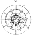
- the plates 14 and 14a are connected according to FIGS. 1 to 3 via star-shaped handlebars 18 with slides 19, which in turn are guided on slide rails 20 which run in a star shape within the cover cone 13.
- the piston-cylinder arrangement 16 is held non-rotatably on a shaft 21 which is fixedly connected to the drive shaft 10 and which simultaneously forms the piston rod of the piston-cylinder arrangement on which the piston 22 is fixed in place.
- the shaft 21 is equipped with longitudinal bores 23 for supplying the pressure medium to the two cylinder spaces of the piston-cylinder arrangement 16.
- the pressure medium is supplied to the bores 23 of the shaft 21 via a rotary transducer 24.
- the closure plates 14 designed as slide plates are in the closed position shown in the left half of FIG. 1 and in FIG. 2 and thus form the peripheral region of the bottom of the drum 1, over which the solid layer 12 builds up.
- the plates 14 are transferred to the open position shown in the right half of FIG. 1 and in FIG. 3, in which they open the ring opening 15. Since the ring opening 15 is located directly below the solid layer 12 and adjoins the peripheral wall 3 of the drum 1 without a step, the solid can fail at a correspondingly low rotational speed of the drum or when the drum is at a standstill and below the drum into a transfer unrecorded receptacle.
- the ring opening 15 is only interrupted by the relatively narrow web-shaped ribs 8 of the arm star, the distance between the arms being so large, however, that no obstruction or bridging of the solid material can occur above the arms.
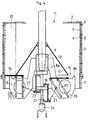
- closure plates 14 are each connected via a parallelogram linkage 25 with downwardly projecting webs 26 of the arms 8 of the arm star.
- the parallelogram linkages 25 are in turn connected via handlebars 27 to the piston cylinder arrangement 16 assigned to all handlebars 27, which has the same design and arrangement as has already been described in connection with FIG. 1.
- the plate-shaped locking elements 14 are moved parallel to themselves on a circular arc section when they are transferred from the lock to the open position and vice versa.
- closure elements 14 are supported on shoulders 8b of the arms 8 of the arm star which point upwards.
- FIG. 5 differs from the embodiment according to FIG. 4 essentially in that the parallelogram linkage 25 protrudes upward from the plate-shaped closure elements 14 into the cover 13 and is articulated there to radially extending supports 28, which in turn are firmly attached the cover 13 are connected.
- the piston-cylinder arrangement 16 deviating from the embodiments according to FIGS. 1 to 4, consists of a plurality of individual cylinders arranged around the drive shaft 10, the number of which is plate-shaped in number Closure elements 14 corresponds.
- the individual cylinders of the piston-cylinder arrangement 15 are actuated synchronously.
- a rotary transducer 24 is provided, from which longitudinal bores (not shown in the drawing) lead through the drive shaft 10 to the cylinders of the piston-cylinder arrangement 16.
- the arrangement of the piston-cylinder arrangement 16 above the cover cone 13 results in a particularly compact construction of the centrifuge drum including the associated devices for emptying the bottom.
- the movable closure plates 14 are designed as hinged plates on a base ring 30.
- the plates 14 are connected on their underside to pivot levers 31, which in turn cooperate with drivers 32 fastened in a star shape to the piston-cylinder arrangement 16.
- the piston-cylinder arrangement 16 is designed in the same way as in the exemplary embodiments in FIGS. 1 to 4.
- the pivoting levers 31 engaging the plates 14 are equipped at their ends facing the drivers 32 with a guide roller 33 which engage in a locking recess in the closed position of the plates 14 and in a guide groove 34 of the driver 32 in the closed position of the plate-shaped closure elements 14.
- the plate-shaped closure elements 14 are formed in their design as swivel plates so that they fill the space between adjacent arms 8 of the arm star and thus form the bottom of the drum 1 together with the aforementioned arms 8 in the closed position.
Landscapes
- Centrifugal Separators (AREA)
Priority Applications (1)
| Application Number | Priority Date | Filing Date | Title |
|---|---|---|---|
| EP92103409A EP0557560A1 (fr) | 1992-02-28 | 1992-02-28 | Centrifugeuse à tamis pour la séparation discontinue de mélanges solides-liquides |
Applications Claiming Priority (1)
| Application Number | Priority Date | Filing Date | Title |
|---|---|---|---|
| EP92103409A EP0557560A1 (fr) | 1992-02-28 | 1992-02-28 | Centrifugeuse à tamis pour la séparation discontinue de mélanges solides-liquides |
Publications (1)
| Publication Number | Publication Date |
|---|---|
| EP0557560A1 true EP0557560A1 (fr) | 1993-09-01 |
Family
ID=8209378
Family Applications (1)
| Application Number | Title | Priority Date | Filing Date |
|---|---|---|---|
| EP92103409A Withdrawn EP0557560A1 (fr) | 1992-02-28 | 1992-02-28 | Centrifugeuse à tamis pour la séparation discontinue de mélanges solides-liquides |
Country Status (1)
| Country | Link |
|---|---|
| EP (1) | EP0557560A1 (fr) |
Cited By (3)
| Publication number | Priority date | Publication date | Assignee | Title |
|---|---|---|---|---|
| FR3026025A1 (fr) * | 2014-09-19 | 2016-03-25 | Fives Cail Babcock | Essoreuse centrifuge a marche discontinue |
| CN107225051A (zh) * | 2017-06-22 | 2017-10-03 | 安徽普源分离机械制造有限公司 | 一种防固相残留的味素离心分离设备 |
| CN116393267A (zh) * | 2023-06-07 | 2023-07-07 | 泰安市泰山汇金智能科技有限公司 | 一种离心机 |
Citations (7)
| Publication number | Priority date | Publication date | Assignee | Title |
|---|---|---|---|---|
| DE109641C (fr) * | ||||
| GB190904296A (en) * | 1909-02-22 | 1910-01-20 | William Allan Macfarlane | Improvements in Centrigugal Machines. |
| GB191222836A (en) * | 1912-10-07 | 1913-07-17 | John Bromet | Improvements in or relating to the Centrifugal Treatment fo Sewage and other Liquids, and in Apparatus for use in connection therewith. |
| US1336779A (en) * | 1915-04-21 | 1920-04-13 | Angus H Gibson | Centrifugal machine |
| FR1247363A (fr) * | 1959-07-24 | 1960-12-02 | Landsverk Ab | Perfectionnements aux centrifugeuses |
| FR1414318A (fr) * | 1963-11-27 | 1965-10-15 | Ohg E Fonderie A Bosco S P A | Dispositif obturateur à volets pour la fermeture des orifices de sortie du panier d'une essoreuse assurant le blocage de l'arbre de l'essoreuse |
| DE1905285A1 (de) * | 1969-02-04 | 1970-08-06 | Salzgitter Maschinen Ag | Vorrichtung zum Verschliessen und Freilegen der Abfuehroeffnung im Boden einer Zentrifugentrommel |
-
1992
- 1992-02-28 EP EP92103409A patent/EP0557560A1/fr not_active Withdrawn
Patent Citations (7)
| Publication number | Priority date | Publication date | Assignee | Title |
|---|---|---|---|---|
| DE109641C (fr) * | ||||
| GB190904296A (en) * | 1909-02-22 | 1910-01-20 | William Allan Macfarlane | Improvements in Centrigugal Machines. |
| GB191222836A (en) * | 1912-10-07 | 1913-07-17 | John Bromet | Improvements in or relating to the Centrifugal Treatment fo Sewage and other Liquids, and in Apparatus for use in connection therewith. |
| US1336779A (en) * | 1915-04-21 | 1920-04-13 | Angus H Gibson | Centrifugal machine |
| FR1247363A (fr) * | 1959-07-24 | 1960-12-02 | Landsverk Ab | Perfectionnements aux centrifugeuses |
| FR1414318A (fr) * | 1963-11-27 | 1965-10-15 | Ohg E Fonderie A Bosco S P A | Dispositif obturateur à volets pour la fermeture des orifices de sortie du panier d'une essoreuse assurant le blocage de l'arbre de l'essoreuse |
| DE1905285A1 (de) * | 1969-02-04 | 1970-08-06 | Salzgitter Maschinen Ag | Vorrichtung zum Verschliessen und Freilegen der Abfuehroeffnung im Boden einer Zentrifugentrommel |
Non-Patent Citations (2)
| Title |
|---|
| GB-A-J4296 (W.A. MACFARLANE) * |
| GB-A-M22836 (J. BROMET) * |
Cited By (4)
| Publication number | Priority date | Publication date | Assignee | Title |
|---|---|---|---|---|
| FR3026025A1 (fr) * | 2014-09-19 | 2016-03-25 | Fives Cail Babcock | Essoreuse centrifuge a marche discontinue |
| CN107225051A (zh) * | 2017-06-22 | 2017-10-03 | 安徽普源分离机械制造有限公司 | 一种防固相残留的味素离心分离设备 |
| CN116393267A (zh) * | 2023-06-07 | 2023-07-07 | 泰安市泰山汇金智能科技有限公司 | 一种离心机 |
| CN116393267B (zh) * | 2023-06-07 | 2023-08-15 | 泰安市泰山汇金智能科技有限公司 | 一种离心机 |
Similar Documents
| Publication | Publication Date | Title |
|---|---|---|
| DE3043993C2 (fr) | ||
| DE2103829A1 (de) | Zentrifuge | |
| EP3630670B1 (fr) | Capsuleuse de type rotatif | |
| EP0255623B1 (fr) | Dispositif pour la séparation de suspensions | |
| DE1482754B1 (de) | Zentrifuge,insbesondere Zuckerzentrifuge | |
| EP0710504B1 (fr) | Centrifugeuse à poussoir | |
| EP0672459B1 (fr) | Centrifugeuse filtrante | |
| EP2782678B1 (fr) | Centrifugeuse discontinue avec racle pour enlever un produit | |
| DE4337618C1 (de) | Stülpfilterzentrifuge (Trommelraumabdichtung) | |
| DE1151221B (de) | Bodenverschluss fuer eine Zentrifuge mit haengender Schleudertrommel | |
| EP0635309B1 (fr) | Centrifugeuse à double poussoir | |
| EP0557560A1 (fr) | Centrifugeuse à tamis pour la séparation discontinue de mélanges solides-liquides | |
| DE2834491C2 (de) | Siebzentrifuge mit gekrümmten Siebtaschen | |
| DE2802653C3 (de) | Fahrzeug zur Beförderung von Müll oder anderem Schüttgut | |
| WO2019170586A1 (fr) | Centrifugeuse à vis sans fin et à bol plein | |
| DE3610229A1 (de) | Mehrstufige schubzentrifuge | |
| DE1288988C2 (de) | Kontinuierlich arbeitende Siebzentrifuge, insbesondere Zuckerzentrifuge | |
| DE1482754C (de) | Zentrifuge, insbesondere Zuckerzentn fuge | |
| EP0455964B1 (fr) | Centrifugeuse | |
| DE2803130A1 (de) | Ein- und austragvorrichtung fuer schaelzentrifugen | |
| DE3417966A1 (de) | Trommelpresse zum abscheiden von fluessigkeit aus einem feststoff | |
| EP1088593B1 (fr) | Centrifugeuse à racleur | |
| DE1906016A1 (de) | Verfahren und Vorrichtung zur Durchfuehrung des Verfahrens zum Auswechseln von Gleitringdichtungen an Ruehrerwellen | |
| EP0230205B1 (fr) | Centrifugeuse travaillant en continu pour malaxer et centrifuger les masses cuites | |
| DE2224764A1 (de) | Bodenverschluss fuer eine zentrifugentrommel |
Legal Events
| Date | Code | Title | Description |
|---|---|---|---|
| PUAI | Public reference made under article 153(3) epc to a published international application that has entered the european phase |
Free format text: ORIGINAL CODE: 0009012 |
|
| 17P | Request for examination filed |
Effective date: 19930511 |
|
| AK | Designated contracting states |
Kind code of ref document: A1 Designated state(s): DE FR GB IT SE |
|
| 17Q | First examination report despatched |
Effective date: 19940801 |
|
| STAA | Information on the status of an ep patent application or granted ep patent |
Free format text: STATUS: THE APPLICATION IS DEEMED TO BE WITHDRAWN |
|
| 18D | Application deemed to be withdrawn |
Effective date: 19951201 |