EP0556856A2 - Dispositif pour la fabrication de glace en copeaux - Google Patents
Dispositif pour la fabrication de glace en copeaux Download PDFInfo
- Publication number
- EP0556856A2 EP0556856A2 EP93102684A EP93102684A EP0556856A2 EP 0556856 A2 EP0556856 A2 EP 0556856A2 EP 93102684 A EP93102684 A EP 93102684A EP 93102684 A EP93102684 A EP 93102684A EP 0556856 A2 EP0556856 A2 EP 0556856A2
- Authority
- EP
- European Patent Office
- Prior art keywords
- channel
- radial
- turns
- channels
- section
- Prior art date
- Legal status (The legal status is an assumption and is not a legal conclusion. Google has not performed a legal analysis and makes no representation as to the accuracy of the status listed.)
- Withdrawn
Links
Images


Classifications
-
- F—MECHANICAL ENGINEERING; LIGHTING; HEATING; WEAPONS; BLASTING
- F28—HEAT EXCHANGE IN GENERAL
- F28F—DETAILS OF HEAT-EXCHANGE AND HEAT-TRANSFER APPARATUS, OF GENERAL APPLICATION
- F28F5/00—Elements specially adapted for movement
- F28F5/02—Rotary drums or rollers
-
- F—MECHANICAL ENGINEERING; LIGHTING; HEATING; WEAPONS; BLASTING
- F25—REFRIGERATION OR COOLING; COMBINED HEATING AND REFRIGERATION SYSTEMS; HEAT PUMP SYSTEMS; MANUFACTURE OR STORAGE OF ICE; LIQUEFACTION SOLIDIFICATION OF GASES
- F25C—PRODUCING, WORKING OR HANDLING ICE
- F25C1/00—Producing ice
- F25C1/12—Producing ice by freezing water on cooled surfaces, e.g. to form slabs
- F25C1/14—Producing ice by freezing water on cooled surfaces, e.g. to form slabs to form thin sheets which are removed by scraping or wedging, e.g. in the form of flakes
- F25C1/142—Producing ice by freezing water on cooled surfaces, e.g. to form slabs to form thin sheets which are removed by scraping or wedging, e.g. in the form of flakes from the outer walls of cooled bodies
Definitions
- the invention relates to a device for producing flake ice from a freezable liquid, in particular water, with a cooling drum arranged in a trough and rotatable via a shaft, which has a body with a channel arranged on its surface for guiding refrigerant, which extends in the form of essentially circumferential windings between the two end regions of the body, is connected on its inflow side to a radial feed channel and on its outflow side to a radial drain channel and is covered by a jacket made of a material of high thermal conductivity, the radial feed channel and the radial drainage channel opens into an axial blind hole extending from one side of the shaft.
- the cooling drum of this known device has a body with a channel running in a spiral along its surface for guiding the refrigerant, the inlet and outlet sides of this channel being arranged in opposite end regions of the body.
- This requires in an arrangement in which the refrigerant supply and the refrigerant outflow from the same side of the refrigeration drum or the shaft should take place, a very deep blind hole extending to the distal end region of the body, which can only be produced in a technically complex manner and on special machines for long cold drums.
- the invention has for its object to provide a device of the type mentioned, which can be manufactured in the simplest possible manner with constant or improved efficiency.
- the radial feed channel and the radial drain channel are arranged in the same end area and the deflection section in the opposite end area of the body.
- claims 3 to 7 advantageously contribute to a uniform and intensive cooling of the jacket surrounding the body, as a result of which a high ice-making capacity is possible.
- At least the majority of the turns consist of a peripheral portion lying in a plane perpendicular to the body axis and an inclined portion connecting the end of the peripheral portion of one turn to the beginning of the peripheral portion of the turn adjacent to the same group in the flow direction of the refrigerant.
- the channel consists of a multiple channel, in particular two, three, four, five or six-channel, which has a corresponding number of separate channels lying next to one another and carrying refrigerants in the same flow direction.
- the same refrigerant throughput can be achieved even at lower supply pressures within the radial feed channels or at lower suction capacities at the radial drainage channels, which offers the particular advantage that flake ice makers of this type can also be operated in a composite system in which several dry ice makers are connected to a common supply line for Refrigerant can be connected.
- the length of time the refrigerant stays within the refrigeration drum is also shortened accordingly, so that a less evaporation and temperature increase of the refrigerant occurs.
- the efficiency, ie the ice making performance of the device is increased.
- the channel is designed as a multiple channel, the cross-section through which it flows can be enlarged without the distance between the intermediate walls or webs supporting the jacket having to be increased.
- the jacket which is made of a highly thermally conductive material, for example aluminum, is therefore supported at a corresponding number of points and can have a correspondingly low material thickness without any risk of deformation, which is advantageous for heat transfer.
- a channel system which consists of several, in particular two to six, individual channels.
- this embodiment has all the advantages and effects which have already been explained in connection with the multiple channel of claim 15.
- the individual channels are not returned to that end area of the body in which the radial feed channel is located, since the radial feed and drain channel are located here in the opposite end areas of the body. It is also decisive here that by multiplying the number of channels, the required refrigerant pressure can be reduced accordingly with the wetted surface of the jacket remaining the same and with the same mass throughput, i.e. with the same speed of the refrigerant within the channel, and thus the use of the ice maker, for example in composite systems with low Supply pressures are possible.
- the supply of the refrigerant for each individual channel can take place on the same side of the cooling drum and the discharge on the opposite side, so that the direction of flow in each individual channel is in the same direction.
- the embodiment according to claim 18 offers the advantage of uniform cooling of the jacket and simple manufacture.
- the embodiment according to claim 19 offers the possibility of accomplishing the refrigerant supply and removal from the various end faces of the refrigeration drum, so that long blind holes are unnecessary.
- FIG. 1 schematically shows a device for producing flake ice with a cylindrical cooling drum 1, which is arranged in a trough 3 filled to a level 2 with a freezable liquid, in particular water.
- the cooling drum 1 consists of a body 4, in the surface of which a channel 5 is provided, which runs in the form of windings around the surface of the body 4.
- the body 4 and thus the channel 5 is covered radially outwards by a hollow cylindrical jacket 6, which consists of a material with high thermal conductivity, for example aluminum.
- a refrigerant flows, which cools the jacket 6 by evaporation, so that an ice layer forms on the outside of the jacket 6, which can be scraped off, for example, with the aid of a scraper, not shown, directed against the jacket 6.
- the cooling drum 1 is rotatably mounted in the side walls of the tub 3 by means of a central shaft 7 which extends axially through the body 4 and is connected to it in a rotationally fixed manner, the two ends of the shaft 7 projecting outward beyond the tub 3.
- the shaft 7 is connected to a motor 9 via a gear 8.
- the shaft 7 has an axial blind hole 10 into which both a radial feed channel 11, which is connected to the start of the channel 5, and a radial discharge channel 12, which is connected to the end of the channel 5, open.
- the refrigerant is fed to the radial feed channel 11 via a tube 13 which is inserted into the blind bore 10 and has a significantly smaller diameter than the blind bore 10 and is discharged via the space between the tube 13 and the shaft 7. Further details on the refrigerant supply and discharge via the shaft 7 can be found, for example, in DE-PS 37 30 806.
- the channel 5 has a U-shaped cross section with a semicircular base section 14 and parallel side walls 15, the depth of the channel 5 being equal to it Width is.
- the width of the channel 5 corresponds to the diameter of the radial feed channel 11 and drain channel 12.
- the intermediate walls 15 have a constant width which is approximately 15 to Is 17% of the channel width.
- Both the radial feed channel 11 and the radial drain channel 12 are arranged in the same end region of the body 4, the radial feed channel 11 being further away from the inflow and outflow end of the cooling drum 1 than the radial outflow channel 12 provided at the very outer end.
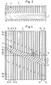
- the channel 4 shows a flat development of the body 4, the direction of flow of the refrigerant being shown by arrows.
- the channel 5 extends, starting from the radial feed channel 11, first in the form of first turns 16 along the surface of the body 4 to the opposite end region, is o deflected there by means of a deflection section 17 by 180 and then centrally in the space between the first windings 16 returned in the form of second turns 18 to the radial drain channel 12.
- Each turn 16 consists of a peripheral section 16a, which lies in a plane 20 perpendicular to the body axis 19, and, with the exception of the outermost turn 16, which merges into the deflection section 17, of an inclined section 16b.
- the oblique section 16b connects, seen in the flow direction of the refrigerant, the end of the peripheral section 16a of one turn 16 to the beginning of the peripheral section 16a of the following turn 16.
- a corresponding design applies to the second turns 18 returning from the deflection section 17 to the radial drainage channel 12, which also consist of a peripheral section 18a and an inclined section 18b.
- Both the peripheral sections 16a, 18a and the inclined sections 16b, 18b are straight in the flat development and have a constant width and depth, whereby simple manufacture is possible, for example, using a milling cutter.
- the transitions from the oblique sections 16b into the circumferential sections 16a of the first turns 16 and the transitions from the circumferential sections 18a into the oblique sections 18b of the second turns 18 lie on a straight line 21 which is one with the body axis 19 Includes angle ⁇ of 22.5 o .
- the opening of the radial feed channel 11 also lies on this straight line 21.
- transitions from the circumferential sections 16a into the oblique sections 16b of the first turns 16 and the transitions from the oblique sections 18b into the circumferential sections 18a of the side turns 18 lie on a straight line 22 parallel to the straight line 21.
- the inner radius of the deflecting section is also at the height of the straight line 22 17 arranged.
- the opening of the radial drain channel 12 is provided at the level of a straight line 23 which runs in the middle between the two straight lines 21 and 22.
- the inclined portions 16b, 18b close to the body axis 19 an angle ⁇ of 45 o a.
- the radial drain channel 12 opens into the first turn 18, as seen from the left, and the radial feed channel 11 into the third turn 16.
- the peripheral section 18 a between the radial feed channel 11 and the radial drain channel 12 arranged second turn 18 extends, viewed in the direction of flow, not only to the straight line 21 but also to the straight line 23, as a result of which the outermost left inclined section 18b is only half as long as the other inclined sections 16b, 18b is formed. This enables a minimization of the body surface not covered by the channel 5 and thus a large-area and uniform cooling of the jacket 6.
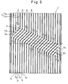
- FIG. 5 shows a body 4 of a cooling drum in a flat development, in which the channel 5 as a double channel with two individual channels 5a, 5b is formed.
- This double channel also extends in a first group of turns 16 spaced apart from one another in the direction of the end region of the body 4 which is distant from the radial feed channel 11 and, after corresponding deflection sections 17a, 17b, is in a second group of opposing ones in the space between the turns 16 of the first Group arranged windings 18 in the direction of the other end region up to the radial drain channels 12a, 12b returned.
- the deflection sections 17a, 17b and the inlet and outlet ends of the channel 5 are in turn arranged such that as large a part of the surface of the body 4 as possible is covered by the channel 5.
- FIG. 6 shows a further embodiment of a body 4 in a flat development, in which the channel is also divided into two individual channels 5a, 5b.
- the feed channel 11 and the two drain channels 12a, 12b for the individual channels 5a, 5b are located in the opposite end regions of the body 4, so that the direction of flow of the refrigerant is the same in all turns. This direction of flow is shown by arrows 24.
- the individual channels 5a, 5b extend here with a constant slope from the inlet end to the outlet end.
- the individual channels 5a, 5b have the same cross-sectional shape and cross-sectional size and are separated from one another by webs or partition walls 15 'which have the same width as the webs or partition walls 15 through which each turn of the Double channel is separated from the adjacent turn.
- the individual channels 5a, 5b are connected to one another at their inlet end and are connected to the radial feed channel 11 in this connection area. At their outlet end, however, the individual channels 5a, 5b open into separate drain channels 12a, 12b.
- the individual channels 5a, 5b open into separate drain channels 12a, 12b.
- other designs are also readily possible, for example separate feed channels and a common drainage channel for the individual channels 5a, 5b.
- the size and shape of the supply and drainage channels can also be adapted and changed to the respective requirements.
- FIG. 7 A further embodiment variant of a body 4 is shown in a flat development in FIG. 7, in which a division into two individual channels 25, 26 is again provided and the inlet openings 11a, 11b and the outlet openings 12a, 12b are located in the opposite end regions of the body 4 are so that the direction of flow of the refrigerant - as indicated by arrow 24 - is the same in all turns.
- the oblique displacement of the individual channels in the area 27 makes it possible in this embodiment to arrange the individual channels 25, 26 practically over their entire circumference in radial planes, ie in planes perpendicular to the longitudinal axis of the body, thereby making optimal use of the available cooling surface results because also in the end regions of the body 4 a uniform course of the channels and thus a full utilization of the available cooling surface is possible.
Landscapes
- Engineering & Computer Science (AREA)
- Physics & Mathematics (AREA)
- Thermal Sciences (AREA)
- Mechanical Engineering (AREA)
- General Engineering & Computer Science (AREA)
- Heat-Exchange Devices With Radiators And Conduit Assemblies (AREA)
Applications Claiming Priority (2)
| Application Number | Priority Date | Filing Date | Title |
|---|---|---|---|
| DE4205214 | 1992-02-20 | ||
| DE4205214A DE4205214A1 (de) | 1992-02-20 | 1992-02-20 | Vorrichtung zur erzeugung von scherbeneis |
Publications (2)
| Publication Number | Publication Date |
|---|---|
| EP0556856A2 true EP0556856A2 (fr) | 1993-08-25 |
| EP0556856A3 EP0556856A3 (en) | 1993-11-10 |
Family
ID=6452200
Family Applications (1)
| Application Number | Title | Priority Date | Filing Date |
|---|---|---|---|
| EP19930102684 Withdrawn EP0556856A3 (en) | 1992-02-20 | 1993-02-19 | Device for making flaked ice |
Country Status (2)
| Country | Link |
|---|---|
| EP (1) | EP0556856A3 (fr) |
| DE (1) | DE4205214A1 (fr) |
Cited By (2)
| Publication number | Priority date | Publication date | Assignee | Title |
|---|---|---|---|---|
| WO1995024596A1 (fr) * | 1994-03-09 | 1995-09-14 | Maja Maschinenfabrik Hermann Schill Gmbh | Machine automatique pour la production de glace en flocons |
| CN111059814A (zh) * | 2018-10-16 | 2020-04-24 | 青岛海尔股份有限公司 | 一种旋转离心式制冰机构及冰箱 |
Families Citing this family (2)
| Publication number | Priority date | Publication date | Assignee | Title |
|---|---|---|---|---|
| DE19507864B4 (de) * | 1995-03-08 | 2005-12-22 | Maja-Maschinenfabrik Hermann Schill Gmbh | Scherbeneisautomat |
| DE19629447B4 (de) * | 1996-07-23 | 2005-05-19 | Maja-Maschinenfabrik Herrmann Schill Gmbh | Scherbeneismaschine |
Citations (11)
| Publication number | Priority date | Publication date | Assignee | Title |
|---|---|---|---|---|
| FR788794A (fr) * | 1934-07-20 | 1935-10-16 | Kestner App Evaporateurs | Perfectionnements aux tambours sécheurs rotatifs |
| US2095363A (en) * | 1933-08-12 | 1937-10-12 | Ig Farbenindustrie Ag | Drum type drier |
| DE859481C (de) * | 1946-05-15 | 1953-01-19 | Escher Wyss Maschinenfabrik G | Waermeaustauscheinrichtung |
| US3143865A (en) * | 1961-12-06 | 1964-08-11 | Anthony J Ross | Liquid freezing apparatus with renewable freezing wall |
| US3187809A (en) * | 1963-01-11 | 1965-06-08 | Inta Roto Machine Company Inc | Heat-exchange roll and method of making |
| US3228462A (en) * | 1965-04-09 | 1966-01-11 | Hupp Corp | Heat exchange apparatus |
| US3534563A (en) * | 1968-11-12 | 1970-10-20 | Anthony J Ross | Liquid freezing apparatus |
| DE1601084A1 (de) * | 1967-12-20 | 1971-02-04 | Schill Maja Masch | Verfahren und Vorrichtung zur Erzeugung von Feineis oder dergleichen Gefrierprodukte |
| US3752227A (en) * | 1972-01-06 | 1973-08-14 | Gen Tire & Rubber Co | Embossing roll with integral cooling means |
| DE2707907A1 (de) * | 1976-02-24 | 1977-08-25 | Trimay Engineering Co | Walze bzw. welle |
| DE9101195U1 (de) * | 1991-02-02 | 1991-04-25 | Maja-Maschinenfabrik Hermann Schill Gmbh, 7640 Kehl | Vorrichtung zum Herstellen und Ablösen von Feineis aus Wasser o.dgl. |
-
1992
- 1992-02-20 DE DE4205214A patent/DE4205214A1/de not_active Withdrawn
-
1993
- 1993-02-19 EP EP19930102684 patent/EP0556856A3/de not_active Withdrawn
Patent Citations (11)
| Publication number | Priority date | Publication date | Assignee | Title |
|---|---|---|---|---|
| US2095363A (en) * | 1933-08-12 | 1937-10-12 | Ig Farbenindustrie Ag | Drum type drier |
| FR788794A (fr) * | 1934-07-20 | 1935-10-16 | Kestner App Evaporateurs | Perfectionnements aux tambours sécheurs rotatifs |
| DE859481C (de) * | 1946-05-15 | 1953-01-19 | Escher Wyss Maschinenfabrik G | Waermeaustauscheinrichtung |
| US3143865A (en) * | 1961-12-06 | 1964-08-11 | Anthony J Ross | Liquid freezing apparatus with renewable freezing wall |
| US3187809A (en) * | 1963-01-11 | 1965-06-08 | Inta Roto Machine Company Inc | Heat-exchange roll and method of making |
| US3228462A (en) * | 1965-04-09 | 1966-01-11 | Hupp Corp | Heat exchange apparatus |
| DE1601084A1 (de) * | 1967-12-20 | 1971-02-04 | Schill Maja Masch | Verfahren und Vorrichtung zur Erzeugung von Feineis oder dergleichen Gefrierprodukte |
| US3534563A (en) * | 1968-11-12 | 1970-10-20 | Anthony J Ross | Liquid freezing apparatus |
| US3752227A (en) * | 1972-01-06 | 1973-08-14 | Gen Tire & Rubber Co | Embossing roll with integral cooling means |
| DE2707907A1 (de) * | 1976-02-24 | 1977-08-25 | Trimay Engineering Co | Walze bzw. welle |
| DE9101195U1 (de) * | 1991-02-02 | 1991-04-25 | Maja-Maschinenfabrik Hermann Schill Gmbh, 7640 Kehl | Vorrichtung zum Herstellen und Ablösen von Feineis aus Wasser o.dgl. |
Non-Patent Citations (1)
| Title |
|---|
| ESCHER WYSS MITTEILUNGEN Bd. 45/46, Nr. 2, 1973, Seiten 51 - 52 PREGER, M. 'Die Kühlwalze unter veränderlichen Betriebsbedingungen' * |
Cited By (2)
| Publication number | Priority date | Publication date | Assignee | Title |
|---|---|---|---|---|
| WO1995024596A1 (fr) * | 1994-03-09 | 1995-09-14 | Maja Maschinenfabrik Hermann Schill Gmbh | Machine automatique pour la production de glace en flocons |
| CN111059814A (zh) * | 2018-10-16 | 2020-04-24 | 青岛海尔股份有限公司 | 一种旋转离心式制冰机构及冰箱 |
Also Published As
| Publication number | Publication date |
|---|---|
| EP0556856A3 (en) | 1993-11-10 |
| DE4205214A1 (de) | 1993-08-26 |
Similar Documents
| Publication | Publication Date | Title |
|---|---|---|
| EP1218186B1 (fr) | Cylindre de presse rotative | |
| DE69525594T2 (de) | Wärmeaustauschrohr | |
| DE60209994T2 (de) | Wärmetauscherrohr | |
| DE69414474T2 (de) | Wärmetauscher mit integriertem Filter | |
| DE60015278T2 (de) | Rotierende Kühlwalze | |
| EP1036296A1 (fr) | Tube plat avec une partie coudee en u, decalee transversalement, et echangeur de chaleur con u a partir de ce dernier | |
| DE102007035271A1 (de) | Elektromotor | |
| DE2423299A1 (de) | Mutter fuer kugelumlaufschraubgetriebe | |
| DE4432972B4 (de) | Wärmetauscher mit zwei Rohrreihen, insbesondere für Kraftfahrzeuge | |
| DE19818589A1 (de) | Brennkraftmaschine | |
| DE2839552B2 (de) | Düsenkopf zum Herstellen von Kunststoffgranulat | |
| DE3500790A1 (de) | Verbesserte eismaschine | |
| EP1798506A2 (fr) | Echangeur de chaleur, en particulier évaporateur | |
| DE3340734C2 (de) | Schnecke einer Schneckenpresse | |
| WO2006120121A2 (fr) | Cylindre de sechage | |
| DE69909017T2 (de) | Giessen eines Stahlbandes | |
| DE60001853T2 (de) | Zylinder für das stranggiessen von metallbändern mit einem kühlkreislauf | |
| EP0556856A2 (fr) | Dispositif pour la fabrication de glace en copeaux | |
| WO2021185828A1 (fr) | Dispositif échangeur | |
| EP1788320A1 (fr) | Echangeur de chaleur | |
| EP1798505A2 (fr) | Echangeur de chaleur, en particulier évaporateur | |
| EP1158188A1 (fr) | Dispositif d'entraínement | |
| DE102005000794A1 (de) | Vorrichtung und Verfahren zur Herstellung und/oder Veredelung einer Faserstoffbahn | |
| DE2013940A1 (de) | Wärmeübertrager für flüssige und gasförmige Medien | |
| DE19507864B4 (de) | Scherbeneisautomat |
Legal Events
| Date | Code | Title | Description |
|---|---|---|---|
| PUAI | Public reference made under article 153(3) epc to a published international application that has entered the european phase |
Free format text: ORIGINAL CODE: 0009012 |
|
| AK | Designated contracting states |
Kind code of ref document: A2 Designated state(s): AT BE CH DE ES FR GB LI NL |
|
| PUAL | Search report despatched |
Free format text: ORIGINAL CODE: 0009013 |
|
| AK | Designated contracting states |
Kind code of ref document: A3 Designated state(s): AT BE CH DE ES FR GB LI NL |
|
| 17P | Request for examination filed |
Effective date: 19940228 |
|
| 17Q | First examination report despatched |
Effective date: 19950621 |
|
| STAA | Information on the status of an ep patent application or granted ep patent |
Free format text: STATUS: THE APPLICATION IS DEEMED TO BE WITHDRAWN |
|
| 18D | Application deemed to be withdrawn |
Effective date: 19951103 |