EP0555856B1 - Verfahren zum Einstellen eines Fühlers bei einer Bahnlaufregeleinrichtung - Google Patents
Verfahren zum Einstellen eines Fühlers bei einer Bahnlaufregeleinrichtung Download PDFInfo
- Publication number
- EP0555856B1 EP0555856B1 EP93102165A EP93102165A EP0555856B1 EP 0555856 B1 EP0555856 B1 EP 0555856B1 EP 93102165 A EP93102165 A EP 93102165A EP 93102165 A EP93102165 A EP 93102165A EP 0555856 B1 EP0555856 B1 EP 0555856B1
- Authority
- EP
- European Patent Office
- Prior art keywords
- sensor
- web
- edge
- measuring range
- operating point
- Prior art date
- Legal status (The legal status is an assumption and is not a legal conclusion. Google has not performed a legal analysis and makes no representation as to the accuracy of the status listed.)
- Expired - Lifetime
Links
- 238000000034 method Methods 0.000 title claims description 20
- 238000009434 installation Methods 0.000 title abstract 2
- 238000006073 displacement reaction Methods 0.000 claims abstract 5
- 230000001960 triggered effect Effects 0.000 abstract 1
- 230000003287 optical effect Effects 0.000 description 5
- 230000012447 hatching Effects 0.000 description 1
Images

Classifications
-
- B—PERFORMING OPERATIONS; TRANSPORTING
- B65—CONVEYING; PACKING; STORING; HANDLING THIN OR FILAMENTARY MATERIAL
- B65H—HANDLING THIN OR FILAMENTARY MATERIAL, e.g. SHEETS, WEBS, CABLES
- B65H23/00—Registering, tensioning, smoothing or guiding webs
- B65H23/02—Registering, tensioning, smoothing or guiding webs transversely
- B65H23/0204—Sensing transverse register of web
Definitions
- the invention relates to a method according to the preamble of claim 1.
- a web guiding device in which the web run is controlled by means of an optical sensor which detects the web edge without contact, the operating point of the control is set to the center of the sensor, so that when the sensor is exactly positioned one half of the sensor is covered by the path to be controlled, while the other half is exposed.
- This operating point is stored in a memory and the web guiding system is designed for this reference variable, so that if the web edge deviates from the operating point, the web guiding system adjusts the web so that the web edge comes to rest on the operating point or the center of the sensor.
- the sensor adjustment device must be activated in order to adjust the sensor in a corresponding way.
- the sensor adjustment device works relatively imprecisely and has a certain overrun, so that with this sensor adjustment this e.g. is moved beyond the intended position.
- the operating point must then be returned using the correction keys and corrected so that it corresponds to the desired position. This adjustment process when the working point is adjusted beyond the measuring range of the sensor is relatively cumbersome.
- the invention has for its object to provide a method of the type mentioned in such a way that the operating point of the control can be easily and quickly adjusted beyond the measuring range of the sensor.
- a threshold is specified in the electronic signal processing device on both sides of the sensor center or the working point.
- a threshold is given by means of which a signal is emitted, on the one hand, by means of which the web guiding system previously working is switched off or is blocked, so that the web edge remains in the position reached, and on the other hand the sensor adjusting device is controlled so that it carries out an edge search process by adjusting the sensor, the center of the sensor being repositioned on the web edge by the exact edge search process.
- the web guiding switched on again and the same process can be repeated until the operating point of the control is in the desired position, which can be far outside the measuring range of the sensor in the original position, whereupon in the new position the measuring range of the sensor for a Working point correction is available.
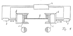
- Fig. 1 shows a schematic representation of circular optical sensors 1 in a U-shaped holder 6, which can be adjusted by a sensor adjusting device 5, on both sides of a material web 2, in which case the web edges cover sensors 1 in half.
- An electronic signal processing and control device is shown schematically at 4, which receives and processes the sensor signals. Furthermore, the sensor adjusting devices 5 for adjusting the sensor 1 are controlled by this control device 4.
- FIG. 2 denotes a circular optical sensor, which in the first position a) is aligned with the center of the sensor on the edge 2 of a material web to be controlled, so that the material web covers one sensor half, as indicated by hatching.
- the working point W of the sensor is first adjusted within the measuring range D of the sensor 1 by means of correction keys to the left from the position a) while the web guiding is switched on, so that the web edge 2 follows the operating point left within the measuring range D is adjusted as shown in position b).
- the web guiding is switched on again and the working point of the sensor is again moved to the left within the measuring range D by means of the correction keys if the working point shift was not sufficient in the first step. If the threshold 3 is reached in this case, the same process is repeated until, for example, an operating point shift shown in position d) is reached which is outside the measuring range D of the sensor 1 is in the original position a).
- the working point is first shifted relatively slowly within the measuring range, whereupon after the threshold 3 is reached, the edge search process is carried out by the sensor adjusting device with increased actuating speed.
- the web edge is first moved into the sensor, whereupon the sensor follows the web edge. If the operating point is shifted in the opposite direction, the web edge is first moved out of the sensor, whereupon the sensor follows the web edge and this step-by-step process is repeated.
- the method according to the invention of shifting the working point beyond the predetermined measuring range can also be carried out in the same way in the case of sensors other than optical sensors, for example pneumatic sensors.
- the described shifting of the working point can be carried out with edge and center control, whereby independently adjustable sensors are used.
- the working point When correcting the working point using correction buttons, the working point is slowly shifted within the measuring range, for example with a rate of change of 1 mm / sec, while during the edge search process the sensor is adjusted with an adjusting speed of for example 30 mm / sec.
- the operating point of the control can be steplessly shifted over the entire adjustment range of the sensor adjustment device, even if the sensor adjustment device only has a detent-like fine adjustment of e.g. Permits 0.5 mm.
- This operating point shift can also be carried out with a web center control that works with sensors that can be adjusted independently of one another.
Landscapes
- Registering, Tensioning, Guiding Webs, And Rollers Therefor (AREA)
- Length Measuring Devices By Optical Means (AREA)
- Controlling Sheets Or Webs (AREA)
- Control Of Conveyors (AREA)
- Paper (AREA)
- Controlling Rewinding, Feeding, Winding, Or Abnormalities Of Webs (AREA)
- Air Bags (AREA)
- Geophysics And Detection Of Objects (AREA)
- Measuring Fluid Pressure (AREA)
- Length Measuring Devices With Unspecified Measuring Means (AREA)
Applications Claiming Priority (2)
| Application Number | Priority Date | Filing Date | Title |
|---|---|---|---|
| DE4203978 | 1992-02-11 | ||
| DE4203978A DE4203978C1 (xx) | 1992-02-11 | 1992-02-11 |
Publications (2)
| Publication Number | Publication Date |
|---|---|
| EP0555856A1 EP0555856A1 (de) | 1993-08-18 |
| EP0555856B1 true EP0555856B1 (de) | 1996-05-22 |
Family
ID=6451418
Family Applications (1)
| Application Number | Title | Priority Date | Filing Date |
|---|---|---|---|
| EP93102165A Expired - Lifetime EP0555856B1 (de) | 1992-02-11 | 1993-02-11 | Verfahren zum Einstellen eines Fühlers bei einer Bahnlaufregeleinrichtung |
Country Status (8)
| Country | Link |
|---|---|
| US (1) | US5379659A (xx) |
| EP (1) | EP0555856B1 (xx) |
| JP (1) | JP2559087B2 (xx) |
| AT (1) | ATE138348T1 (xx) |
| CA (1) | CA2089248A1 (xx) |
| DE (2) | DE4203978C1 (xx) |
| DK (1) | DK0555856T3 (xx) |
| ES (1) | ES2087586T3 (xx) |
Families Citing this family (4)
| Publication number | Priority date | Publication date | Assignee | Title |
|---|---|---|---|---|
| JP3557196B2 (ja) * | 2002-03-29 | 2004-08-25 | 株式会社東京機械製作所 | 連続紙処理装置の連続紙走行位置修正装置 |
| US20090321491A1 (en) * | 2008-06-06 | 2009-12-31 | Wick William R W | Edge Detection System |
| US20110204611A1 (en) * | 2010-02-18 | 2011-08-25 | Daimler Trucks North America Llc | Fiber reinforced polymer frame rail |
| CN103264919A (zh) * | 2013-05-10 | 2013-08-28 | 奇瑞汽车股份有限公司 | 一种卷材纠偏控制系统 |
Family Cites Families (16)
| Publication number | Priority date | Publication date | Assignee | Title |
|---|---|---|---|---|
| US2786675A (en) * | 1953-09-03 | 1957-03-26 | Goodrich Co B F | Side position regulating apparatus |
| GB1192499A (en) * | 1968-08-06 | 1970-05-20 | Mount Hope Machinery Ltd | Arrangement for Controlling the Lateral Position of a Moving Web of Material |
| US3568904A (en) * | 1969-08-01 | 1971-03-09 | Gpe Controls Inc | Sample data web and strip guide control system |
| US3682362A (en) * | 1971-03-15 | 1972-08-08 | Rockford Servo Corp | Web edge sensing and guiding apparatus |
| US3786974A (en) * | 1972-07-19 | 1974-01-22 | Eastman Kodak Co | Web edge guide system |
| DD123663A1 (xx) * | 1975-05-12 | 1977-01-12 | ||
| US4077579A (en) * | 1976-04-12 | 1978-03-07 | Columbia Ribbon & Carbon Mfg. Co., Inc. | Edge alignment apparatus |
| US4291825A (en) * | 1979-04-19 | 1981-09-29 | Baldwin-Korthe Web Controls, Inc. | Web guiding system |
| JPS5719246A (en) * | 1980-07-02 | 1982-02-01 | Hitachi Cable Ltd | Meandering corrector for elongated matters |
| US4331274A (en) * | 1980-10-14 | 1982-05-25 | Itek Corporation | Tracking system |
| JPS5842904A (ja) * | 1981-09-08 | 1983-03-12 | Mitsutoyo Mfg Co Ltd | 測長装置 |
| USRE32967E (en) * | 1982-11-24 | 1989-06-27 | Xerox Corporation | Web tracking system |
| DE3614981A1 (de) * | 1986-05-02 | 1987-11-05 | Erhardt & Leimer Gmbh | Verfahren und vorrichtung zum fuehren einer laufenden warenbahn |
| JPH0657580B2 (ja) * | 1986-11-19 | 1994-08-03 | 富士写真フイルム株式会社 | ウエブの蛇行修正方法及び装置 |
| US4991761A (en) * | 1988-10-31 | 1991-02-12 | Web Printing Controls Co., Inc. | Web guide apparatus |
| US5098507A (en) * | 1991-01-28 | 1992-03-24 | Mao Chen Chi | Relieved plastic floor tile rolling press with an automatic alignment device |
-
1992
- 1992-02-11 DE DE4203978A patent/DE4203978C1/de not_active Expired - Fee Related
-
1993
- 1993-02-10 CA CA002089248A patent/CA2089248A1/en not_active Abandoned
- 1993-02-10 US US08/016,018 patent/US5379659A/en not_active Expired - Fee Related
- 1993-02-10 JP JP5045672A patent/JP2559087B2/ja not_active Expired - Fee Related
- 1993-02-11 EP EP93102165A patent/EP0555856B1/de not_active Expired - Lifetime
- 1993-02-11 DE DE59302632T patent/DE59302632D1/de not_active Expired - Fee Related
- 1993-02-11 DK DK93102165.3T patent/DK0555856T3/da active
- 1993-02-11 AT AT93102165T patent/ATE138348T1/de not_active IP Right Cessation
- 1993-02-11 ES ES93102165T patent/ES2087586T3/es not_active Expired - Lifetime
Also Published As
| Publication number | Publication date |
|---|---|
| CA2089248A1 (en) | 1993-08-12 |
| ATE138348T1 (de) | 1996-06-15 |
| DK0555856T3 (da) | 1996-10-14 |
| DE59302632D1 (de) | 1996-06-27 |
| JP2559087B2 (ja) | 1996-11-27 |
| ES2087586T3 (es) | 1996-07-16 |
| US5379659A (en) | 1995-01-10 |
| JPH0680306A (ja) | 1994-03-22 |
| DE4203978C1 (xx) | 1993-08-19 |
| EP0555856A1 (de) | 1993-08-18 |
Similar Documents
| Publication | Publication Date | Title |
|---|---|---|
| EP0243756B1 (de) | Verfahren und Vorrichtung zum Führen einer laufenden Warenbahn | |
| DE3244828A1 (de) | Automatisch sich bewegendes fahrzeug vom lern-wiedergabe-typ | |
| DE3145195A1 (de) | Registerregler fuer eine etikettenschneidmaschine | |
| DE3430750C2 (xx) | ||
| EP0555856B1 (de) | Verfahren zum Einstellen eines Fühlers bei einer Bahnlaufregeleinrichtung | |
| DE4203947C2 (de) | Verfahren zum Einstellen eines die Bahnkante einer laufenden Materialbahn berührungsfrei erfassenden Fühlers | |
| DE2025935C3 (de) | Vorrichtung zur Stabilisierung der Bildstellung in einem beweglichen Sichtgerät | |
| DE69030243T2 (de) | Verfahren und Gerät zur Steuerung von Ladungsträgerstrahlen in einem Belichtungssystem mittels Ladungsträgerstrahlen | |
| CH688185A5 (de) | Verfahren zum Funkenentladungsschneiden einer Innenecke eines Werkstueckes. | |
| DE2528789C2 (de) | Reproduktionsapparat | |
| EP0555855B1 (de) | Verfahren zum Positionieren eines Fühlers für eine Bahnlaufregeleinrichtung | |
| EP0555854B1 (de) | Verfahren zum Positionieren der Fühler bei einer Bahnlaufregeleinrichtung | |
| DE2929487C2 (xx) | ||
| DE3125449C2 (xx) | ||
| DE2146121B2 (de) | Blasluftsteuerung für Bogenanleger | |
| DE2538060C3 (de) | Einem Regler vorgeschaltete Vorrichtung | |
| EP0268803B1 (de) | Kreuzwagen-Brennschneidmaschine | |
| EP0434610B1 (de) | Verfahren und Vorrichtung zum Positionieren des Fadenverbands einer Schärmaschine | |
| EP0142743A1 (de) | Fotografisches Kopiergerät | |
| DE2349073C3 (de) | Elektrische Kopiersteuerungsvorrichtung mit einem fotoelektrisch einen Linienzug oder eine Kante abtastenden Abtastkopf | |
| DE1588967A1 (de) | Maschine zum elektrischen Perforieren einer Schablone | |
| DE2559949C2 (de) | Elektrische Steuerungsvorrichtung für die Wegbegrenzung des Werkzeug- oder Werkstückträgers einer Honmaschine | |
| DE925751C (de) | Photokopiergeraet | |
| DE2512055C3 (de) | Vorrichtung zur Belichtungssteuerung | |
| EP0042085B1 (de) | Vorrichtung zum Transport von Aufzeichnungspapier in Schreib- und dergleichen Büromaschinen |
Legal Events
| Date | Code | Title | Description |
|---|---|---|---|
| PUAI | Public reference made under article 153(3) epc to a published international application that has entered the european phase |
Free format text: ORIGINAL CODE: 0009012 |
|
| AK | Designated contracting states |
Kind code of ref document: A1 Designated state(s): AT BE CH DE DK ES FR GB IT LI NL SE |
|
| 17P | Request for examination filed |
Effective date: 19940105 |
|
| 17Q | First examination report despatched |
Effective date: 19940902 |
|
| GRAH | Despatch of communication of intention to grant a patent |
Free format text: ORIGINAL CODE: EPIDOS IGRA |
|
| GRAA | (expected) grant |
Free format text: ORIGINAL CODE: 0009210 |
|
| AK | Designated contracting states |
Kind code of ref document: B1 Designated state(s): AT BE CH DE DK ES FR GB IT LI NL SE |
|
| REF | Corresponds to: |
Ref document number: 138348 Country of ref document: AT Date of ref document: 19960615 Kind code of ref document: T |
|
| REG | Reference to a national code |
Ref country code: CH Ref legal event code: NV Representative=s name: SCHMAUDER & WANN PATENTANWALTSBUERO, INHABER KLAUS |
|
| REG | Reference to a national code |
Ref country code: ES Ref legal event code: BA2A Ref document number: 2087586 Country of ref document: ES Kind code of ref document: T3 |
|
| ITF | It: translation for a ep patent filed | ||
| REF | Corresponds to: |
Ref document number: 59302632 Country of ref document: DE Date of ref document: 19960627 |
|
| REG | Reference to a national code |
Ref country code: ES Ref legal event code: FG2A Ref document number: 2087586 Country of ref document: ES Kind code of ref document: T3 |
|
| ET | Fr: translation filed | ||
| GBT | Gb: translation of ep patent filed (gb section 77(6)(a)/1977) |
Effective date: 19960829 |
|
| REG | Reference to a national code |
Ref country code: DK Ref legal event code: T3 |
|
| PLBE | No opposition filed within time limit |
Free format text: ORIGINAL CODE: 0009261 |
|
| STAA | Information on the status of an ep patent application or granted ep patent |
Free format text: STATUS: NO OPPOSITION FILED WITHIN TIME LIMIT |
|
| 26N | No opposition filed | ||
| PGFP | Annual fee paid to national office [announced via postgrant information from national office to epo] |
Ref country code: DK Payment date: 19980127 Year of fee payment: 6 |
|
| PGFP | Annual fee paid to national office [announced via postgrant information from national office to epo] |
Ref country code: SE Payment date: 19980206 Year of fee payment: 6 |
|
| PGFP | Annual fee paid to national office [announced via postgrant information from national office to epo] |
Ref country code: ES Payment date: 19980211 Year of fee payment: 6 |
|
| PGFP | Annual fee paid to national office [announced via postgrant information from national office to epo] |
Ref country code: AT Payment date: 19980224 Year of fee payment: 6 |
|
| PGFP | Annual fee paid to national office [announced via postgrant information from national office to epo] |
Ref country code: NL Payment date: 19980228 Year of fee payment: 6 |
|
| PGFP | Annual fee paid to national office [announced via postgrant information from national office to epo] |
Ref country code: BE Payment date: 19980304 Year of fee payment: 6 |
|
| PG25 | Lapsed in a contracting state [announced via postgrant information from national office to epo] |
Ref country code: AT Free format text: LAPSE BECAUSE OF NON-PAYMENT OF DUE FEES Effective date: 19990211 |
|
| PG25 | Lapsed in a contracting state [announced via postgrant information from national office to epo] |
Ref country code: SE Free format text: LAPSE BECAUSE OF NON-PAYMENT OF DUE FEES Effective date: 19990212 Ref country code: ES Free format text: LAPSE BECAUSE OF NON-PAYMENT OF DUE FEES Effective date: 19990212 |
|
| PG25 | Lapsed in a contracting state [announced via postgrant information from national office to epo] |
Ref country code: BE Free format text: LAPSE BECAUSE OF NON-PAYMENT OF DUE FEES Effective date: 19990228 |
|
| PG25 | Lapsed in a contracting state [announced via postgrant information from national office to epo] |
Ref country code: DK Free format text: LAPSE BECAUSE OF NON-PAYMENT OF DUE FEES Effective date: 19990301 |
|
| BERE | Be: lapsed |
Owner name: BST SERVO-TECHNIK G.M.B.H. Effective date: 19990228 |
|
| PG25 | Lapsed in a contracting state [announced via postgrant information from national office to epo] |
Ref country code: NL Free format text: LAPSE BECAUSE OF NON-PAYMENT OF DUE FEES Effective date: 19990901 |
|
| EUG | Se: european patent has lapsed |
Ref document number: 93102165.3 |
|
| REG | Reference to a national code |
Ref country code: DK Ref legal event code: EBP |
|
| REG | Reference to a national code |
Ref country code: ES Ref legal event code: FD2A Effective date: 20010910 |
|
| REG | Reference to a national code |
Ref country code: GB Ref legal event code: IF02 |
|
| PGFP | Annual fee paid to national office [announced via postgrant information from national office to epo] |
Ref country code: GB Payment date: 20020211 Year of fee payment: 10 |
|
| PGFP | Annual fee paid to national office [announced via postgrant information from national office to epo] |
Ref country code: FR Payment date: 20020221 Year of fee payment: 10 |
|
| PGFP | Annual fee paid to national office [announced via postgrant information from national office to epo] |
Ref country code: CH Payment date: 20020308 Year of fee payment: 10 |
|
| PG25 | Lapsed in a contracting state [announced via postgrant information from national office to epo] |
Ref country code: GB Free format text: LAPSE BECAUSE OF NON-PAYMENT OF DUE FEES Effective date: 20030211 |
|
| PG25 | Lapsed in a contracting state [announced via postgrant information from national office to epo] |
Ref country code: LI Free format text: LAPSE BECAUSE OF NON-PAYMENT OF DUE FEES Effective date: 20030228 Ref country code: CH Free format text: LAPSE BECAUSE OF NON-PAYMENT OF DUE FEES Effective date: 20030228 |
|
| GBPC | Gb: european patent ceased through non-payment of renewal fee | ||
| REG | Reference to a national code |
Ref country code: CH Ref legal event code: PL |
|
| PG25 | Lapsed in a contracting state [announced via postgrant information from national office to epo] |
Ref country code: FR Free format text: LAPSE BECAUSE OF NON-PAYMENT OF DUE FEES Effective date: 20031031 |
|
| REG | Reference to a national code |
Ref country code: FR Ref legal event code: ST |
|
| PG25 | Lapsed in a contracting state [announced via postgrant information from national office to epo] |
Ref country code: IT Free format text: LAPSE BECAUSE OF NON-PAYMENT OF DUE FEES;WARNING: LAPSES OF ITALIAN PATENTS WITH EFFECTIVE DATE BEFORE 2007 MAY HAVE OCCURRED AT ANY TIME BEFORE 2007. THE CORRECT EFFECTIVE DATE MAY BE DIFFERENT FROM THE ONE RECORDED. Effective date: 20050211 |
|
| PGFP | Annual fee paid to national office [announced via postgrant information from national office to epo] |
Ref country code: DE Payment date: 20060426 Year of fee payment: 14 |
|
| PG25 | Lapsed in a contracting state [announced via postgrant information from national office to epo] |
Ref country code: DE Free format text: LAPSE BECAUSE OF NON-PAYMENT OF DUE FEES Effective date: 20070901 |