EP0552791B1 - Gerät und Verfahren zum Extrahieren von Kantendaten und zur Kodierung von Bilddaten mit diesen Kantendaten - Google Patents
Gerät und Verfahren zum Extrahieren von Kantendaten und zur Kodierung von Bilddaten mit diesen Kantendaten Download PDFInfo
- Publication number
- EP0552791B1 EP0552791B1 EP93100949A EP93100949A EP0552791B1 EP 0552791 B1 EP0552791 B1 EP 0552791B1 EP 93100949 A EP93100949 A EP 93100949A EP 93100949 A EP93100949 A EP 93100949A EP 0552791 B1 EP0552791 B1 EP 0552791B1
- Authority
- EP
- European Patent Office
- Prior art keywords
- outline
- vector
- edge
- data
- vectors
- Prior art date
- Legal status (The legal status is an assumption and is not a legal conclusion. Google has not performed a legal analysis and makes no representation as to the accuracy of the status listed.)
- Expired - Lifetime
Links
Images


Classifications
-
- G—PHYSICS
- G06—COMPUTING; CALCULATING OR COUNTING
- G06T—IMAGE DATA PROCESSING OR GENERATION, IN GENERAL
- G06T9/00—Image coding
- G06T9/20—Contour coding, e.g. using detection of edges
-
- G—PHYSICS
- G06—COMPUTING; CALCULATING OR COUNTING
- G06T—IMAGE DATA PROCESSING OR GENERATION, IN GENERAL
- G06T7/00—Image analysis
- G06T7/10—Segmentation; Edge detection
- G06T7/12—Edge-based segmentation
-
- G—PHYSICS
- G06—COMPUTING; CALCULATING OR COUNTING
- G06V—IMAGE OR VIDEO RECOGNITION OR UNDERSTANDING
- G06V10/00—Arrangements for image or video recognition or understanding
- G06V10/40—Extraction of image or video features
- G06V10/42—Global feature extraction by analysis of the whole pattern, e.g. using frequency domain transformations or autocorrelation
- G06V10/421—Global feature extraction by analysis of the whole pattern, e.g. using frequency domain transformations or autocorrelation by analysing segments intersecting the pattern
-
- G—PHYSICS
- G06—COMPUTING; CALCULATING OR COUNTING
- G06V—IMAGE OR VIDEO RECOGNITION OR UNDERSTANDING
- G06V10/00—Arrangements for image or video recognition or understanding
- G06V10/40—Extraction of image or video features
- G06V10/46—Descriptors for shape, contour or point-related descriptors, e.g. scale invariant feature transform [SIFT] or bags of words [BoW]; Salient regional features
- G06V10/469—Contour-based spatial representations, e.g. vector-coding
-
- G—PHYSICS
- G06—COMPUTING; CALCULATING OR COUNTING
- G06T—IMAGE DATA PROCESSING OR GENERATION, IN GENERAL
- G06T2207/00—Indexing scheme for image analysis or image enhancement
- G06T2207/10—Image acquisition modality
- G06T2207/10004—Still image; Photographic image
- G06T2207/10008—Still image; Photographic image from scanner, fax or copier
-
- G—PHYSICS
- G06—COMPUTING; CALCULATING OR COUNTING
- G06T—IMAGE DATA PROCESSING OR GENERATION, IN GENERAL
- G06T2207/00—Indexing scheme for image analysis or image enhancement
- G06T2207/30—Subject of image; Context of image processing
- G06T2207/30176—Document
Definitions
- the present invention relates to an apparatus and method for extracting outline data of image data or coded image data.
- an outline font is formed from image data which is expressed by a binary image pattern
- an outline of the binary image pattern is extracted and expressed by vectors. Extraction of the outline of the binary image pattern starts with searching a start point for tracing.
- Numeral 201 is a binary image pattern having a closed area 202 inside. Extraction of outlines from this pattern is described below. It should be noted that, in Fig. 2, each piece of lattice represents a dot (pixel) and shaded pixel represents a black pixel.
- a dot represented by ⁇ is a dot of interest
- a dot represented by (pixel 401) is a dot of the outline traced immediately before the dot ⁇ .
- Numbers in the figures represent the order of searching pixels.
- the outline is traced in a unit of pixel, instead of outline of pixel. Therefore, if a part of the image pattern having one-dot width is traced, the drawback is that the width is regarded as "0" and the outline of the one-dot is not appeared.
- the received coded data needs to be once developed to an image pattern in order to obtain the outline of the image data. Accordingly, the processing amount is increased, a memory to develop the pattern is required, and a size of the hardware is enlarged.
- an image pattern is obtained by filling dots in a closed area formed by the outlines and then coded data is obtained by scanning this image pattern, thus resulting in a complication in the process.
- an object of the present invention to provide an outline extraction apparatus and method capable of efficiently obtaining outlines of image data.
- Fig. 1 is a block diagram illustrating the construction of an outline extraction apparatus of the first embodiment according to the present invention.
- This apparatus obtains vectors forming an outline from coded image data received as MH code data and outputs vector data to a magnetic disk in a form of coordinate data (coordinates of start point and end point).
- a microprocessor (CPU) 1 connects to RAM 2, MH coder/decoder 3, I/O port 4, and ROM 7 through a bus 6.
- a control procedure of the CPU 1 is stored in the ROM 7 in a form of program.
- the bus 6 connects to a magnetic disk 5 through the I/O port 4.
- it is arranged so as to obtain coordinates of an outline dot from the received coded image data.
- it can be arranged so as to obtain the coordinates from the coded image data which is stored in the magnetic disk 5 in advance.
- the obtained coordinate data is stored in the magnetic disk 5 in this embodiment.
- this does not impose a limitation upon the invention.
- another process such as enlargement/reduction process can be performed by using the outline dot coordinates.
- FIG. 5 illustrates a procedure for control program process stored in the ROM 7 and this process is executed by the CPU 1. The procedure starts when the coded image data is read for one page into the RAM 2.
- the abbreviations used in Fig. 5 are:
- SLC and SLP are stored in a work area provided in the RAM 2.
- a value of the SLP is preset so as to instruct a leading scanning line of the coded data of that page.
- the coded data (SLC) of the scanning line instructed by the pointer SLP is read out from the RAM 2 and decoded. Since the coded data is an MH code, decoded data represent a run length of white/black pixel.
- step S3 outline vectors are extracted from data which has been decoded at step S2. The detail of this process will be described later.
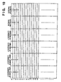
- step S4 referring to the outline vector table (Fig. 9), if there is a pair of vectors, in the vector table, in which directions are opposite to each other and a start/end point of one vector is an end/start point of the other vector, the outline vector obtained at step S3 is removed from the vector table and eliminated. The rest of vectors are registered with the vector table and the process proceeds to step S5.
- step S5 the pointer (SLP) is advanced to the next scanning line position.
- step S6 it is judged whether a process for one page has ended. If the result is "NO”, the process returns to step S2, while if the result is "YES", the process ends.
- Fig. 6A is a diagram to explain the outline vectors.
- the shaded area is an area corresponding to black pixels and points (61, 62, 63, 64) at the four corners of the pattern respectively indicate a center of the black pixel. It is assumed that the coordinates of the four points are (2, 2), (5, 2), (5, 3), (2, 3) and arrows along with the outline of this pattern are outline vectors.
- An outline vector always keeps a black pixel on the right side and outline vectors are arranged in the clockwise direction. However, this arrangement can be inverted so as to keep the black pixel on the left side, in the counterclockwise direction.
- a start point/end point of the outline vector is located on an intersecting point of the main scanning line and sub-scanning line.
- a location of a pixel is represented by a positive integer and two dimensional coordinates.
- four connecting vectors (arrows) in Fig. 6A have four points of the coordinate system such as (1.5, 1.5), (5.5, 1.5), (5.5, 3.5), and (1.5, 3.5). Each of which is a start point of one vector and end point of the other vector.
- Each of the four vectors is expressed as follows:
- a decimal number is avoided and a position of pixel (a center of each pixel) are expressed by even numbers as shown in Fig. 6B, and the coordinates of start/end point of a vector are expressed by odd numbers. That is, an image of m ⁇ n pixels is expressed by 2m ⁇ 2n in the coordinates of positive even integers. Accordingly, the image pattern having the points 61 ⁇ 64 in Fig. 6A can be expressed by the coordinates (4, 4), (10, 4), (10, 6), (4, 6). The start/end points of each vector are (3, 3), (11, 3), (11, 7), (3, 7). Accordingly, the four vectors in Fig. 6B are expressed as:
- a binary image is comprised of m (pixels) ⁇ n (rasters) (wherein m, n are positive integers) and the i-th pixel position of the j-th raster is expressed by (2i, 2j) (i ⁇ m, j ⁇ n, wherein i, j are positive integers).
- step S11 it is tested whether or not the process for all pixels of a scanning line of interest has ended. If the process has ended, the process of step S3 ends. If the process has not ended, the process proceeds to step S12 where whether or not a pixel of interest is a black pixel. If the pixel is not black, a pixel of interest is advanced to the next pixel of the line and the process returns to step S11. On the other hand, if it is a black pixel, the process proceeds to step S13 where a perimeter of the pixel is determined as outline vectors. That is, if the pixel of interest is located at (m, n), the outline vector is expressed by:
- step S14 it is examined if there is a vector in which the vector direction is opposite to the obtained outline vector. If there is any, that pair of vectors is eliminated. This indicates that a partial process of updating the outline vector table at step S4 is performed with respect to the subscanning direction, If there is a pair of vectors in which the direction is opposite to each other (the start and end points of one vector are the same as the end and start points of the other vector), this pair of vectors is eliminated because the pixels on both sides of the pair of vectors are continuing.
- step S15 a pixel of interest is advanced to the next pixel.
- a raster of interest (8 pixels) becomes all white pixels at step S2 since a scanning line of interest (SLP) is preset to a leading scanning line of the image data.
- SLP scanning line of interest
- there is no outline no process is performed at step S3 and S4.
- the scanning line of interest is advanced to the next line and the process returns to step S2 based upon the judgment of step S6.
- the MH code is decoded and it is examined if a black pixel is included in the image data.
- the scanning line of interest is comprised of 3 white pixels, 1 black pixel, and 4 white pixels. Accordingly, since it is recognized that there is a black pixel at the fourth pixel on the scanning line of interest from the information obtained at step S3, the outline vectors of the black pixel are extracted. As apparent from Fig. 8B, the outline vectors are expressed by the aforementioned method as follows:
- Fig. 10 is an outline vector table showing the data obtained by registering the outline vector data of Fig. 8B.
- Fig. 10 vertically arranged numbers on the left end represent vector numbers and the coordinates of a start point and end point of each vector are registered.
- the second vector is called as an "incoming vector" to the first vector.
- the third vector is called as an "outgoing vector" to the first vector.
- an incoming vector of the vector No. 0 is the vector No. 3 and an outgoing vector is the vector No. 1.
- the scanning line of interest is advanced to the next line and the process proceeds to step S2.
- the outline vectors of the four black pixels are extracted at step S3.
- Each outline vector can be obtained in a unit of pixel as shown in Fig. 8C.
- a pair of vectors in which the direction is opposite to each other is eliminated.
- the following pairs are eliminated:
- group B a group of vectors which can be obtained from Fig. 8C is as follows:
- each of vectors in which the start point value and end point value are replaced by each other is compared with the vector data registered with the outline vector table (Fig. 10). If there is any pair, it is removed.
- [(7, 5), (9, 5)] in the vector group B is matched with the vector No. 2 in the outline vector table, both vectors [(7, 5), (9, 5)] and [(9, 5), (7, 5)] are eliminated and the data of the vector table becomes as Fig. 11.
- the outgoing vector of the vector No. 1 is changed from the vector No.
- the scanning line of interest is advanced to the next line (scanning line 8 of Fig. 8A) and, if the outline vector extraction process has not ended for one page, the process returns to step S2 where the MH code is read and decoded and the information of pixel arrangement (2 white, 1 black, 1 white, 1 black, and 3 black pixels) can be obtained.
- a group of vectors hereinafter referred to as a "group C"
- group C a group of vectors
- step S4 the outline vector data (Fig. 11) which has already registered with the outline vector table and the vectors of the group C in which the start point and end point are replaced by each other are compared, and, if there is any matched vectors, it is eliminated.
- the vector Nos. 9 and 11 in the outline vector table are matched with the data such as [(5, 7), (7, 7)] and [(9, 7), (11, 7)]
- these vectors are eliminated and the table is updated as shown in Fig. 12.
- the scanning line of interest is advanced to the next line (scanning line 10 in Fig. 8A) and process at step S2 is performed again since the outline vector extraction for one page has not ended yet.
- step S6 it is judged that the outline vector extraction for one page has ended and the process ends.
- each of vector data in the outline vector table is examined to determine if there are at least two continuously arranged vectors either in vertical direction or horizontal direction. If there are any, they are combined into one vector. If the y coordinate of the start point is the same as that of the end point, it is judged that these vectors are horizontal vectors. On the other hand, if the x coordinate of the start point is the same as that of the end point, it is judged that 5 these vectors are vertical vectors.
- the vectors No. 5 and No. 6 are continually arranged in the horizontal direction, they are combined into one vector.
- the vectors No. 12 and No. 15 are continuously arranged in the vertical direction, they are combined into one vector.
- the updated data is shown in Fig. 13.
- the vector No. 6 is incorporated into the vector No. 5 and the x coordinate of the end point and outgoing vector number of the vector No. 5 are changed to the x coordinate of the end point and the outgoing number of the vector No. 6. Furthermore, if there is any vector in which the incoming vector number is "6", it is changed to "5" (vector No. 7).
- the vector No. 12 is incorporated into the vector No. 15. The y coordinate of the end point and outgoing vector number of the vector No. 15 are changed to the y coordinate of the end point and outgoing number of the vector No. 12. Furthermore, if there is any vector in which the incoming vector number is "12”, it is changed 5 to "15" (vector No. 4).
- the incorporated vector is represented by the vector in the start point side, however, this does not impose a limitation upon the invention. It can be arranged that the vector number in the end point side can be used or these settings can be combined.
- the pixel 153 is on the scanning line of interest and the center of the pixel 153 is located at (2i, 2j).
- the centers of the pixels 151 and 152 are respectively located at (2(i - 1), 2(j - 1)), (2(i + 1), 2(j - 1)).
- the vector 154 of the pixel 151 registered with the outline vector table is [(2i - 1, 2(j - 1) - 1), (2i - 1, 2j - 1)], the outgoing vector number of the vector 154 is changed to the vector 155, that is, [(2i - 1, 2j - 1), (2i + 1, 2j - 1)].
- the outline vector 156 of the pixel 153 in which the end point is (2i - 1, 2j - 1) is connected to the vectors 157.
- the incoming vector number of the outline vector 155 is changed to the number of the outline vector 154.
- the incoming vector number of the outline vector 157 [(2i - 1, 2j - 1), (2i - 3, 2j - 1)] is changed to the vector number of the outline vector 156 [(2i - 1, 2j + 1), (2i - 1, 2j - 1)] and the outgoing vector number of the outline vector 156 is changed to the vector number of the outline vector number 157.
- the incoming vector number of the outline vector 158 [(2i + 1, 2j - 1), (2i + 1, 2(j - 1) - 1)] of the pixel 152 registered with the outline vector table is changed to the vector number of the outline vector 155 of the pixel 153 and the outgoing vector number of the outline vector 155 is changed to the vector number of the outline vector 158.
- the outgoing vector number of the outline vector 159 [(2(i + 1) + 1, 2j - 1), (2i + 1, 2j - 1)] of the pixel 152 is changed to the vector number of the outline vector number 160 [(2i + 1, 2j - 1), (2i + 1, 2j + 1)] of the pixel 153 and the incoming vector of the outline vector 160 is changed to the vector number of the outline vector 159.
- the data of the outline vector table is examined again.
- the total number (N) of loop of the image data and the number (L) of vertices of each loop are stored.
- the total number (N) is "1".
- the table of vertex coordinates (131 ⁇ 1314) is formed and the outline vector extraction processing ends.
- Fig. 17 shows a data format of a general outline table. That is, at the beginning of the table, the number of loop (N) in the image is stored, then the number of vertices of each loop (L o ⁇ L N-1 ) and the coordinates of the vertices in each loop are sequentially stored.
- step S21 the number of closed loops in a page is initialized to 0.
- step S22 the outline vector table is examined from the beginning and vector on which the process has not performed is present. If it is not present, it means that the page is blank, thus the process ends. If there is any vector on which the process has not performed, the process proceeds to step S23 where that vector is determined as a vector of interest. In this case, since it is known that there is at least one closed loop, the number of closed loop is added by "1" (S24). At step S25, the number of vertices in the loop is preset to "0".
- step S26 it is examined if the vector of interest and the outgoing vector of the vector of interest are in the same direction. In order to examine the directions, the coordinate of the start point of the vector of interest and the coordinate of the end point of the outgoing vector are compared. If x elements or y elements of the coordinates of two points are identical, it is judged that both vectors are in the same direction. If it is judged that both vectors are in the same direction, the process proceeds to step S29 where the vector of interest is marked as a vector on which the process has performed.
- step S26 if it is judged that the direction are opposite to each other, the process proceeds to step S27 where the number of vertices in the loop is added by "1" because it can be judged that the end point of the vector of interest is a vertex.
- step S28 the coordinate of the end point of the vector of interest is set to the coordinate of the vertex of the loop.
- step S29 a mark indicating that the process has ended is filled with a blank for the vector of interest in the outline vector table.
- step S30 an outgoing vector of the current vector of interest is determined as an updated vector of interest.
- step S31 whether or not the process has already performed on that vector. If the process has performed, it means that the closed loop has gone around and the process returns to step S22 where another vector to which the process has not performed is searched in the outline vector table. If the process has performed, the process returns to step S26 where vertices in the next loop is examined.
- the number of loop (N), the number of vertex (L i ), and the coordinates of vertices are stored in the outline table shown in Fig. 17.
- the outline vectors can be directly extracted from the coded data by the above-described method, a capacity of memory can be reduced in comparison with the conventional method that the coded data are decoded and the pattern image is stored in the memory, thus resulting in the high-speed outline vector extraction processing.
- the coded data are sequentially decoded and the black run length (the number of pixel) and a start point and end point of this black run are calculated.
- the outline data can be extracted in the same manner as that of the case where the MH codes are decoded in the first embodiment.
- the outline vectors can be extracted in the same manner as that of the first embodiment by calculating black run length (the number of pixel) and the coordinates of a start point and end point of this black run.
- step S4 of Fig. 5 in the process for comparing the registered outline vectors and newly obtained outline vectors and judging which vectors are eliminated (step S4 of Fig. 5), if the data registered with the outline vector table are all searched, an amount of processing is increased. Therefore, out of the newly obtained outline vectors, the horizontal vector in which y-coordinate is (2j - 1) (It is assumed that y-coordinate of a currently processing line is 2j) and the horizontal vector in which y-coordinate is (2j - 1) registered with the outline vector table are compared and it is judged whether or not they are eliminated. Accordingly, the amount of processing is considerably reduced and a high-speed processing is enabled.
- the MH coder/decoder 3 is capable of receiving coded data or raw data from the magnetic disk 5 and extracting an outline vector from the data.
- Fig. 19 is a block diagram illustrating the construction of the outline extraction apparatus of the second embodiment.
- outline vectors are extracted from the image data and outputted to the magnetic disk 5.
- the construction of the circuit is almost same as that of the first embodiment, however, the present embodiment differs from the first embodiment in that image data is inputted from the image input unit 8.
- variables i and j are respectively set to "1".
- the variable i performs a function as a counter which counts pixels in the main scanning direction.
- the variable j also performs a function as a counter which counts pixels in the subscanning direction. Both variables are set in work areas reserved in the RAM 2.
- step S42 it is judged whether the pixel of interest (2i, 2j) is a black pixel or white pixel. If the pixel is white, the process proceeds to step S46, while black, to step S43.
- step S43 the following four outline vectors surrounding the pixel of interest (2i, 2j) are extracted (Fig.
- step S44 the outline vector table is searched. If there is a vector which overlaps with the vector a, the vector a and overlapping vector are eliminated from the table. If there is a vector which overlaps with the vector d, the vector d and overlapping vector are eliminated from the table. Overlappying the vector x with vector y means that a start/end point of one vector is an end/start point of the other vector. It is assumed that vectors respectively overlappying with vectors b, c do not exist at this point. Furthermore, if the outline vector table is searched from the latest data to the oldest data, a time required for searching is reduced.
- step S45 a vector number indicating a direction and positions of the vectors connecting to the vector of interest (an incoming vector number/outgoing vector number) which are registered with the outline vector table are updated.
- the detail of this process is illustrated by the flowchart of Fig. 21.
- the outline vector table is comprised of coordinates of start and end point of a vector, vector number of a vector in which an end point is a start point of the vector of interest (referred to as an "incoming vector"), and a vector in which a start point is an end point of the vector of interest (referred to as an "outgoing vector”).
- vector directions of "incoming vectors” or “outgoing vectors” for four outline dots (2i - 1, 2j - 1), (2i + 1, 2j - 1), (2i - 1, 2j + 1), (2i + 1, 2j +1) of the pixel of interest (2i, 2j) are defined as follows:
- step S61 the outline vector table is searched and an incoming vector or outgoing vector for the outline dot A (2i - 1, 2j - 1) in Fig. 22 is obtained.
- the outline vector table is searched in order from the latest to the oldest data.
- step S62 If there is an incoming vector or outgoing vector for the outline dot A is present, the process proceeds to step S63, while if there is not, the process proceeds to step S64.
- Figs. 23A ⁇ 230 illustrate possible arrangements of the four pixels (the arrangement where the four pixels are all in white is omitted). If the coordinates of the middle point of the four pixels is (2i - 1, 2j - 1), the pixel of interest in Fig. 22 will be located at the right bottom of the figure and the pixel should be 5 black. The arrangements where the pixel at the right bottom is black are those of Fig. 23A, 23B, 23C, 23D, 23E, 23F, 23G, 23H, eight arrangements. However, the arrangement of Fig. 23H indicates the case where neither an incoming vector nor outgoing vector is present at 0 step S62.
- step S63 in the case where one incoming vector and one outgoing vector are present, that is, in the case of six arrangements (except the arrangements of Figs. 23G and 23H) from the eight arrangements, the 5 outgoing vector number of the incoming vector is changed to the vector number of the outgoing vector and the incoming vector number of the outgoing vector is changed to the vector number of the incoming vector.
- the outgoing vector number of a positive vertical incoming vector is changed to the vector number of a positive horizontal outgoing vector.
- a vector g3 which was the outgoing vector of a vector g1 is changed to a vector g2.
- a vector g4 which was the incoming vector of the vector g2 is changed to the vector g1.
- an outgoing vector number of a negative vertical incoming vector is changed to a 5 negative horizontal outgoing vector and an incoming vector number of a negative horizontal outgoing vector is changed to the vector number of a negative vertical incoming vector.
- the outgoing vector of the vector g4 is changed from the vector g2 to 0 the vector g3.
- the incoming vector of the vector g3 is changed from the vector g1 to the vector g4.
- the outline vector table is searched and an incoming vector or outgoing vector for the 5 outline dot B (2i + 1, 2j - 1) in Fig. 22 is obtained.
- Figs. 23A ⁇ 230 it is assumed that the coordinates of the middle point of the four pixels is (2i + 1, 2j - 1). Since the pixel at the left bottom corresponds to the pixel of interest in Fig. 22, this pixel is black, and the pixel at the right bottom should be next processed. This case is represented by the arrangements of Figs. 23I, 23J, 23K, 23L. In this case, since the pixel at the right bottom of the outline dot B (2i + 1, 2j - 1) has not processed yet, there should be incoming 5 and outgoing vectors.
- step S65 If there are one incoming vector and outgoing vector, that is the cases of Figs. 23I, 23J, 23K, the outgoing vector number of an incoming vector is changed to the vector number of an outgoing vector and an incoming vector number of an outgoing vector is changed to that of the incoming vector. If there are two of incoming vectors and outgoing vectors, that is the case of Fig. 23L, the outgoing vector number of the positive horizontal incoming vector is changed to the vector number of a negative outgoing vector. At the same time, the incoming vector number of the negative vertical outgoing vector is changed to the vector number of the positive horizontal incoming vector number. Furthermore, the outgoing vector number of the negative horizontal incoming vector is changed to the vector number of the positive vertical outgoing vector. Furthermore, the incoming vector number of the positive outgoing vector is changed to the vector number of the negative horizontal incoming vector.
- step S66 the outline vector table is searched and an incoming vector or outgoing vector of the outline dot C (2i + 1, 2j + 1) in Fig. 22 is obtained. Only the arrangement of Fig. 23M satisfies the condition. In the case of Fig. 23M, since there is a vector which comes into the outline dot C and goes out from the outline dot C, at step S67, the outgoing vector number of the incoming vector is changed to the vector number of the outgoing vector, while the incoming vector number of the outgoing vector is changed to the vector number of the incoming vector.
- the outline vector table is searched and a vector which comes into the outline dot D (2i - 1, 2j + 1) in Fig. 22 or goes out from the outline dot D is searched.
- the arrangements of Figs. 23N and 230 are the cases. Since each of the above vectors is present, at step S69, the outgoing vector number of the incoming vector is changed to the vector number of the outgoing vector and the incoming vector number of the outgoing vector is changed to the vector number of the incoming vector.
- step S49 the variable i is reset to "0"
- the variable j is added by "1" in order to advance the scanning line of interest at step S50 and the 5 process returns to step S47.
- step S51 the outline vector table is scanned. If there are at least two continuously arranged horizontal or 0 vertical vectors, they are incorporated into one vector. Accordingly, the outline vector table including the total number of loop (N) of the image, the number of vertex in each loop (L), coordinates of vertices in each loop is generated as shown in Fig. 17 and the outline 5 vector extraction process ends.
- the procedure for generating the outline table of Fig. 17 from the outline vector table of Fig. 9 can be performed in a same manner that of the first embodiment.
- the outline vectors can be extracted by reading the image in a unit of one pixel (dot), the whole image is not necessary to be stored in a page memory, thus resulting in reduction of the amount of memory.
- step S44 of Fig. 20 of the second embodiment overlapping vectors are eliminated by comparing the outline vectors registered with the table and the outline vectors newly obtained
- the amount of processing is increased.
- a time required for searching can be reduced by searching only the vectors in which the y-coordinate of the start/end point is (2j - 1).
- an outline which is directed to a predetermined direction is used as an outline of an image pattern. That is, it is expressed by a group of outline vectors (line elements) connecting in the clockwise direction or counterclockwise direction as shown in Fig. 24.
- a figure of interest is obtained (Fig. 25).
- an area of the left side of the outline vectors connecting in the counterclockwise direction is shaded, a figure of interest is obtained (Fig. 26).
- a direction and slope of each outline vector is determined. Based upon the determination, both edge points or points rather than the edge points of the vector of interest are determined to form a boundary of the closed area. Subsequently, a length between an even-numbered edge point of a boundary and the odd-numbered edge point of the boundary in a horizontal direction is calculated as a black run length. A length from the even-numbered edge point to the odd-numbered edge point is calculated as a white run. The coded data is then outputted.
- Fig. 27 is a block diagram indicating an example that the coding apparatus-of the third embodiment is applied to a facsimile apparatus.
- numeral 101 is a controller which controls the whole apparatus
- numeral 102 is a reader which reads photoelectrically and inputs an original image
- numeral 103 is an outline data file which stores document data or image data in a form of outline vector data.
- Numeral 104 is an operation unit which is operated by an operator and inputs an instruction for transmission/reception of the original image.
- Numeral 105 is a display which displays various message to an operator and a state of each unit.
- Numeral 106 is a recorder which records a received image or an original image read by the reader 102 by a heat sensitive method or electronic photographing method.
- Numeral 107 is a modem which performs modulation or demodulation of the image data
- numeral 108 is a network control unit (NCU).
- NCU network control unit
- Numeral 111 is a CPU such as a microprocessor which controls all over the apparatus in accordance with the control program stored in a ROM 112.
- Numeral 112 is ROM which stores the control program of the CPU 111 and various data.
- Numeral 113 is a RAM which is used as a work area of the CPU 111 and stores various data.
- Numeral 114 is a buffer memory which stores the image data read by the reader 102 or the outline vector data read out from the data file 103.
- Numeral 115 is a coder which encodes the original image data read by the reader 102 and forms coded data from the outline vector data which is a characteristic of this embodiment.
- Numeral 116 is a decoder which decodes the received coded data and forms the image data.
- Numeral 117 is a transmission/reception buffer which stores the coded image data to be transmitted or the received coded image data. Since the process for coding and transmitting the image data read by the reader is well known, the process for coding the image data based on the outline data is described below.
- the outline data stored in the outline data file 103 is comprised of data (N) indicating the number of closed loop included in the image which is a subject, a group of data (L) indicating the number of vertices comprising each loop, and coordinates of each vertex (x, y).
- data (N) indicating the number of closed loop included in the image which is a subject
- group of data (L) indicating the number of vertices comprising each loop
- coordinates of each vertex (x, y) coordinates of each vertex (x, y).
- vertices in a closed loop is expressed as a group of data retaining the relationship of the vertices positioned next to each other in accordance with the predetermined direction and order on the closed loop.
- the outline data is regarded as a group of data which are arranged in the predetermined direction.
- Fig. 24 is an example of the outline data arranged in the clockwise direction and the data on the pattern obtained by that outline data is shown in Fig. 28.
- the outline of the image pattern F1 of Fig. 24 is expressed by a string of points with the point A as a start point in the clockwise direction, such as A ⁇ B ⁇ C ⁇ D ⁇ E ⁇ F ⁇ G ⁇ H ⁇ I ⁇ J ⁇ A.
- the number of closed loop (N) is "1”
- the number (L) of vertices is "10"
- coordinates of each vertex are sequentially arranged.
- the origin (0, 0) is located at the left corner
- the main scanning direction (to the right) is an x axis
- the subscanning direction (to the vertical direction) is a y axis as shown in Fig. 24.
- the outline is arranged in the clockwise direction.
- a start point in each closed loop can be an arbitrary point in the loop.
- Fig. 29 is a flowchart indicating the procedure of the operation process by the CPU 111 in the facsimile apparatus according to the third embodiment.
- step S71 the process proceeds to step S72 where it is judged whether or not the instruction to transmit the outline data is inputted from the operation unit 104 through the facsimile apparatus. If the instruction is inputted, the process proceeds to step S73 where the outline data is inputted from the outline data file 103 and stored in the buffer memory 114.
- the outline data means a group of outline vector data expressed in a form shown in Figs. 17 and 28.
- step S74 data corresponding to each of edges e1 ⁇ e10 of Fig. 24 in a form of packet data shown in Fig. 31 are formed, an edge table (ET) shown in Fig. 32 is formed, and the process proceeds to step S75.
- the packet data is formed only for an edge which is not parallel to the x axis. Each edge is represented by one pixel per horizontal line, but a start point of each edge is not registered. The detail of the edge table generation process is described later.
- the process proceeds to step S76 where an active edge table (AET) as Fig. 33 is generated at the position of the scanning line of interest.
- AET active edge table
- run lengths of white run and black run are calculated and Huffman code corresponding to each run length is outputted based on the AET. The process of step S77 will be also described later.
- step S79 it is judged wether or not the process to the position of the last scanning line in the page has ended. In the case where the process has ended, the process proceeds to step S80 and a series of processes end. In the case where the process has not ended, the process returns to step S76 where the process for the next line is continued. Judgement if the process has ended is performed by storing the number of the scanning lines included in the page in advance and comparing the number of scanning lines and the current position of the scanning line of interest.
- edge table (ET) generation process at step S74 of Fig. 29 is described with reference to the flowchart of Fig. 34.
- This edge table is generated in the RAM 113.
- step S81 When started, the process proceeds to step S81 where the ET is initialized.
- address pointer areas A y0 ⁇ A yN (which may be referred to as "pointer packet" areas) for the number of the scanning line included in the page to be generated are reserved on the RAM 113 and a maker value " ⁇ " indicating that no reference data is present in the area is stored (refer to Fig. 35).
- step S82 the number of closed loops (N) of the outline data given in Fig. 17 is referred and the process proceeds to step S83.
- step S83 it is examined if the number of the closed loops (N) is larger than "0".
- step S98 a series of the processes ends and the process returns to the main processing.
- step S84 a closed loop
- step S84 the pointer is preset to the position where the number of vertices in the loop No. 0 is stored in the table and the process proceeds to step S85.
- step S85 the vertex data of the loop at the position designated by the pointer is referred and the process proceeds to step S86. If the number of vertices in the loop is rather than "2", the process proceeds to step S87. On the other hand, if it is not, the process proceeds to step S98.
- step S88 it is determined that edge data of next edge (e2) in which the first vertex of the loop (the vertex No. 0 (A)) is a start point and the second vertex of the loop (the vertex (B)) is an end point, a direction and inverse of slope of the edge are obtained in the same manner as that of step S87.
- the process proceeds to step S89 where the pointer of the vertex of interest is set to the address value storing the data on the vertex No. 0 shown in Fig. 17 (the vertex A in Fig. 28) and the process further proceeds to step S90.
- the current edge data (the direction of the current edge and inverse of slope of the edge) is determined as a previous edge data (the previous edge of an edge on interest).
- current edge data is obtained from the next edge data.
- a next edge data (the direction of the next edge and inverse of slope of the edge) is obtained in the same manner as that of step S87.
- a start point of the next edge is the end point of the current edge.
- the end point of the next edge is the next vertex on the loop with respect to the end point of the current edge.
- the above-described process data can be performed by referring to the data of the next vertex of the vertex of interest and the further next vertex.
- the start point of the next edge is the vertex No. 0 (A) and the end point of the next edge is the vertex No. 1 (B).
- the start point of the next edge is the vertex No. N (J) and the end point of the next edge is the vertex No. 0 (A).
- step S92 the process proceeds to step S93, the packet data as shown in Fig. 31 is generated based on the previous edge data, current edge data, and next edge data (refer to Fig. 32). This packet data is added to the edge table in order to update the table. The detail of this processing will be described later with reference to Figs. 36 and 37.
- step S94 a value of pointer of the vertex of interest is updated and determined as a position of the next vertex on the loop.
- step S95 it is judged whether the process for all edges in the loop has ended.
- step S96 the process proceeds to step S96, while if it has not ended, the process returns to step S90 where a series of processing to the next edge is continued. Whether or not the process for the all edges has ended is judged by counting the number of times the process of step S95 has be gone through by each loop and if the counted number is over the number of vertex included in the loop is determined.
- step S96 the pointer is advanced to the position holding data of the next loop and the process proceeds to step S97.
- step S97 it is judged whether or not a series of processes for the all loops included in the outline data has ended. If it has ended, the process proceeds to step S98, while if it has not ended, the process returns to step S85 where a series of processes for the next loop is continued. Whether or not the process for the all edges has ended is judged by counting the number of times the process of step S97 has be gone through by each loop and if the counted number is over the number of vertex included in the loop is determined.
- step S98 the edge table (ET) generation process ends and the process returns to the main routine.
- the edge table updating process at step S93 of Fig. 34 is illustrated by the flowcharts of Figs. 36 and 37. prior to describe these flowcharts, the updating process is described with reference to Fig. 30.
- the process is proceeded by using directions of the current edge, previous edge, and next edge and a ratio of increment of x and y.
- the rules for generating packet data of Fig. 31 is shown in Fig. 30.
- a current edge is indicated by a solid arrow
- a previous edge is indicated by a dot line
- a direction of edge is indicated by a direction of arrow
- a black area is indicated by shade.
- a current edge is indicated by a solid arrow
- the next edge is indicated by a dot arrow
- a direction of edge is indicated by a direction of arrow.
- An area indicated by slant line of each edge is an black data area.
- packet data is generated by determining that the end point of the current edge is at the actual point. If the next edge lies toward the left (case end 4 ), it is determined that the end point of the current edge is located at a point shifted for one scanning line to the start point from the actual point along with the current edge, and packet data is generated based on the determination. If the next edge lies toward the right (case end 5), it is determined that the end of the current edge is located at an actual point and packet data is generated based on this determination.
- next edge In the case where the next edge is downward (case end 8), it is determined that the end point of the current edge is located at an actual point and packet data is generated based on this 0 determination. In the case where the next edge lies toward to the right (case end 10), it is determined that the end point of the current edge is located at a point shifted for one scanning line to the start point along with the current edge and packet data is generated based 5 on this determination. Determination of either "case end 6" or "case end 7" is performed by comparing an inverse slop ⁇ x cur of the current edge and that ⁇ x next of the next edge.
- the packet data shown in Fig. 31 are generated for the current edge.
- step S93 when a series of the processes starts, the process proceeds to step S931.
- Input data are previous edge data updated at step S90 of Fig. 34 (a direction of the previous edge and an inverse slope ⁇ X pre ), current edge data updated at step S91 (coordinates of start point of the current edge (x start , y start ), coordinates of end point (x end , y end ), and a direction and inverse slope ⁇ X cur of the current edge), and next edge data generated at step S92 (a direction of the next edge and an inverse slope ⁇ x next ).
- it is determined whether or not the direction of the current edge data is horizontal whether the current edge lies toward to the right or the left). If the current edge is horizontal (parallel to the x axis), the process proceeds to step S944 where a series of processes ends and the process returns to the subroutine (step S94 of Fig. 34).
- step S932 it is determined whether or not the current edge is upward. If it is upward, the process proceeds to step S933 where packet data for upward edge is generated. On the other hand, if the current edge is not upward (that is, downward), the process proceeds to step S945 where packet data for downward edge is generated.
- the pointer is added by a marker " ⁇ " indicating that there is no connecting edge packet.
- step S933 is a y value of one of the end points which is larger than that of the other.
- x min and “y min” respectively mean x value and y value of the coordinates in which the y value is smaller than that of the other.
- An inverse slope ⁇ x means a change of the x coordinate per scanning line when a point on the current edge moves from a smaller value to a larger value of the y coordinate along with the current edge.
- y max , x min , ⁇ x, and y min are determined as described above.
- step S934 it is determined whether or not the previous edge is downward. If it is downward, the process proceeds to step S935, while if it is not, the process proceeds to step S936.
- step S935 whether the start point of the current edge is "case start 2" or "case start 3" is determined in the above-described method. If it is “case start 2", the process proceeds to step S937 where "1" is subtracted by y max . If not, the process proceeds to step S938.
- step S936 whether or not the start point of the current edge is "case 4" (that is, "case start 1" or "case start 5") is determined. If it is "case start 4", the process proceeds to step S938.
- step S937 where "1" is subtracted by y max . That is, the start point of the upward edge is shifted for one scanning line toward the end point as described above.
- step S938 the process for the start point in the case where the current edge is upward ends.
- step S938 it is determined whether or not the next edge is downward. If it is downward, the process proceeds to step S939, while if it is not, the process proceeds to step S940.
- step S939 whether the end point of the current edge is "case end 2" or "case end 3" is determined in the above-described method. If it is "case end 2", the process proceeds to step S943, while if not ("case end 3"), the process proceeds to step S941.
- step S940 whether or not the next edge lies toward to the left, that is, whether or not the end point of the current edge is "case end 4" (either "case end 1" or "case end 5" is determined.
- step S941 x min is increased by ⁇ x. That is, the x coordinate value is corrected since the end point of the upward edge is shifted for one scanning line toward the start point. If not, the process proceeds from step S940 to step S943 where the packet data is registered with the ET.
- step S942 y min is added by "1". That is, the y coordinate value of the end point is corrected since the end point of the upward edge is shifted for one scanning line toward the start point.
- step S943 the process proceeds to step S943.
- step S946 it is determined if the previous edge is upward. If so, the process proceeds to step S947, while if not, the process proceeds to step S948.
- step S947 whether the start point of the current edge is "case start 6" or "case start 7" is determined in the above-described method. If it is “case start 6" (a vertex of the convex pattern), the process proceeds to step S951. If it is “case start 7" (a vertex of the concave pattern), the process proceeds to step S949. At step S948, whether or not the start point of the current edge is "case start 9" (that is, either "case start 8" or "case start 10") is determined. If it is "case start 9" (the previous edge lies toward the left), the process proceeds to step S949. If not, the process proceeds to step S951. At step S949, x min is increased by ⁇ x.
- step S949 the process proceeds to step S950 where y min is added by "1". That is, the value is corrected since the start point of the downward edge is shifted for one scanning line toward the end point. Accordingly, the process for the start point of the current edge ends.
- step S950 When the process of step S950 ends, the process proceeds to step S951 where whether or not the next edge is upward is determined. If it is upward, the process proceeds to step S952, while if not, the process proceeds to step S953. At step S952, whether the end point of the current edge is "case end 6" or "case end 7" is determined in the above-described method. If it is "case end 6", the process proceeds to step S943 of Fig. 36, while if it is "case end 7", the process proceeds to step S954. At step S953, whether or not the end point of the current edge is "case end 9" (that is, either "case end 8" or "case end 10") is determined.
- step S943 If it is "case end 9", the process proceeds to step S943, while if not, the process proceeds to step S954 where "1" is subtracted from y max . That is, the end point of the downward edge is shifted for one scanning line toward the start point.
- step S954 ends, the process proceeds to step S943.
- the edge packets for the current edge are generated in accordance with the rules of Fig. 30 in the cases where the current edge is upward and downward.
- step S943 When the value of the pointer packet Ayy min is a value rather than " ⁇ ", since it indicates that there are some connected edge packets, these edge packets of the current edge are sorted to a string of the connected edge packets so that values x min of the edge packets are arranged in ascending order with respect to the pointer packet. This is executed when the pointer value of the previous packet which is immediately before the edge packet is copied on a pointer of the edge packet of the current edge and the pointer value of the previous packet is replaced by the address value of the edge packet of the current edge. Accordingly, when the process of step S943 ends, the process proceeds to step S944 where a series of processes for updating the edge table ends and the process returns to the subroutine.
- the outline generation process for a scanning line of interest at step S76 in Fig. 29 is described.
- the process proceeds in accordance with the following procedure (1) - (5) by using an active edge table (AET).
- AET active edge table
- the AET is preset at step S75 and a first state is a state where the marker ⁇ indicating an empty state is written. After this, if the process once ends and proceeds to step S77, this state is retained until the process returns to step S76.
- RL(i) represents a white run length when "i" is an even number, while it represents a black run length when "i" is an odd number.
- the scanning line of interest is updated at step S78 and whether or not the processing for a page ends is determined at step S79. If it has not ended, the process returns to step S76. If it has ended, a code indicating "EOP" (end of page) is outputted and the process ends.
- An edge packet is not generated since the edge e2 is horizontal.
- An edge packet is not generated since the next edge e4 is horizontal.
- An edge packet is not generated since the edge e7 is a horizontal edge.
- edge e9 is an upward edge
- the start point (H) is "case start 3”
- the end point (I) is "case end 1”
- the above data is transformed to an edge table shown in Fig. 39.
- y max and y min are integers which are not negative.
- X min and ⁇ x are actual-number data (that is, the data having information on decimal fraction) which are accurate enough for the operation.
- an x coordinate when the scanning line is advanced to the next line is a value that the x coordinate value of the previous edge is added by a calculated x.
- the pixel on the memory can be located only at a position represented by an integer. Therefore, when ⁇ x is added and there is a carried out from the decimal fraction, the x coordinate is modified and rounded off.
- a method and apparatus generating the MH codes from the edge packet data are described.
- a method and apparatus generating MR codes from edge packet data is described.
- a conventional method for generating MR codes is described in lines 79 - 83 in Image Signal Processing for Fax and OA written by Tadahiko Fukimuke (published by Nikkan Kogyo Shinbun).
- an image is scanned and a transition pixel is searched one by one.
- the method in this embodiment differs from the conventional method in that a transition pixel is searched from edge packet data. Since when a transition pixel has been searched, the following processes are the same as those of the conventional method, only the method for searching the transition pixel from the edge packet data is described below.
- a transition pixel means a pixel in which a color is changed from that of the previous pixel in a same scanning line.
- coding is performed by using a correlation of two dimensions, two active edge table (AET), an AET (CUR) for a scanning line of interest and AET (PRE) for a previous scanning line (a reference scanning line) are needed.
- AET active edge table
- CUR AET
- PRE AET
- Five types of transition pixels are firstly defined prior to describing the MR coding process.
- the pixel a 0 is a hypothetical point which is located immediately after the last pixel (on the right end) of the scanning line.
- steps S701 - 704 of Fig. 43 are the same as step S71 -74 of Fig. 29, a description for steps S701 - 704 is omitted.
- the AET(PRE) for a reference scanning line and AET(CUR) for a scanning line of interest are preset.
- a position of the scanning line of interest is set to the beginning of the scanning line in a page.
- the AET in the scanning line of interest shown in Fig. 33 is generated.
- an edge packet at the position of the scanning line of interest is added and the AET(CUR) is generated by sorting the edge packet in order from the smallest x min .
- step S707 the position of the five types of transition pixels a 0 , ,a 1 , a 2 , b 1 , b 2 are determined by using the AET(PRE) and AET(CUR), a mode is determined based upon a positional relation, and a corresponding code shown in Fig. 42 is outputted.
- step S707 will be described later.
- step S708 a content of the AET(CUR) is copied on the AET(PRE).
- an edge packet in which value y max is the same as a scanning line number is eliminated as described in the third embodiment.
- step S709 the scanning line of interest is advanced to the next line.
- step S710 it is determined if the above process has ended through the last scanning line in the page. If it has not ended, the process proceeds to step S706, while if it has ended, the process ends.
- Fig. 44 is a flowchart illustrating the process of detecting the position of a transition pixel at step S707 and outputting coded outputs.
- the coordinate (0, 0) of the origin as defined in Fig. 24 is changed to (1, 1) in Fig. 44.
- values of y max and x min are respectively added by "1".
- a 1 (a 1 p, a 1 c) is detected.
- a 1 is a transition pixel which is located on the right of a 0 on the scanning line of interest.
- x min cur(i), x min pre(j) respectively indicate a value of x min of the i-th edge packet of the active edge table corresponding to the scanning line of interest and a value of x min of the j-th edge packet of the active edge table corresponding to the reference scanning line.
- a data structure of a 0 , a 1 , a 2 , b 1 , b 2 is comprised of an area 260 (xp) indicating a pixel position and an area 261 (xc) indicating a color of the pixel at that position as shown in Fig. 45.
- the color of the pixel indicated by the j-th edge packet in the active edge table is black when "i" is an odd number, while it is white when "i" is an even number. Therefore, instead of the color of the pixel, a flag indicating whether "i" is an odd number or even number can be adopted.
- a 0 p and "a 0 c” respectively indicate a position of the pixel of a 0 and a flag indicating whether "i" is an odd number (P) or even number (C).
- a 1 p and a 1 c, a 2 p and a 2 , b 1 p and b 1 c, b 2 p and b 2 c respectively indicate each of the above.
- b 1 (b 1 p, b 1 c)
- b 1 p CP[x min pre(i 1 )]
- b 1 c CC(i)
- b 2 (b 2 p, b 2 c)
- step S728 it is determined if
- step S729 a code of the vertical mode is outputted.
- step S731 the operation for detecting a 2 is performed.
- step S734 a code of the horizontal mode is outputted.
- step S936 for "case start 1" and step S940 for "case end 1" shown in Figs. 36 and 37 are modified in accordance with the modification of the above-described rules. It can be also understood that step S948 for "case start 8" and step S953 for "case end 8" are modified.
- a vertex which is common in two contiguous edges which are both upward or downward can be processed as either a point of the edge in which the end point is the vertex or a point of the edge in which the start point is the vertex. If the cases where the vertex is processed as a point on the both edges or as a point which is not located on neither of the edges are avoided, the process can be processed in either of the above ways.
- the outline is described as one expressed by the clockwise data. This does not impose a limitation upon the present invention, for example, it can be applied to the counterclockwise data.
- the rules for generating the edge packets shown in Fig. 46 can be used. In this case, the way of dealing a start point of the current edge is determined by directions of slopes of the current edge and previous edge and the way of dealing an end point of the current edge is determined by directions of slopes of the current edge and next edge.
- the process for updating the edge table in accordance with the rules for generating the edge packet of the counterclockwise data is the same as that of Figs. 36 and 37. The difference is that "Y" and "N" are replaced by each other at steps S936, S940, S948, and S953.
- the origin of the coordinates is located on the upper left of the image, however, this does not impose a limitation upon the invention.
- the method for determining a direction or processing y max , y min , x max , and ⁇ x are modified so as to correspond to a position of the origin or direction of the coordinates, a similar process to the above embodiments is enabled.
- an edge in which the start point is also the end point is eliminated in advance from a string of vertices of the edge comprising an outline.
- this does not impose a limitation upon the present invention. That is, when the edge data is examined, the above process can be continued while the data on the point edge is ignored.
- the process of Fig. 34 in the procedure for generating the current edge data (step S87), the next edge data (step S88), and the next edge data (step S92), if the edge being processed is a point edge, then the point edge is skipped, and data for the next vertex is read and the process can be continued as the vertex is (x end , y end ). In this case, updating a position of the vertex of interest and counting the number of vertices which have been already processed can be adjusted in accordance with the number of skipped vertices. Accordingly, the point edge can be eliminated during the edge table generation.
- the pointer packet can be a two dimensional structure as Fig. 47.
- the pointer packet is comprised of a term having the y coordinate (y min ) of an end point which is smaller than that of the other of the edge packet to be connected to the pointer packet (It should be noted that y min of a plurality of edges are all the same in the case where the plurality of edge packets are sequentially connected from the pointer packet), a term of a pointer for the next pointer packet in the pointer packet having an edge packet to be connected, and a term of the pointer for the edge packet to be connected to that pointer packet.
- Fig. 48 is an example of the edge table comprised of the pointer packet in a form of Fig. 47.
- Fig. 48 is the edge table for the outline pattern given in Fig. 24.
- the edge table having the two dimensional structure can be comprised in a similar way to that of the above embodiments. However, a pointer packet area is not reserved for the number of scanning lines of an image in advance. It is determined whether or not there is a pointer packet having y min indicating an edge packet of interest in the obtained pointer packets whenever an edge packet is generated. If there is, the edge packet is added to a string of the edge packets comprising the pointer packet. If not, a new pointer packet is generated and y min is stored in the new pointer packet. The edge packet is connected and the newly generated pointer packet is added and sorted in the string of the pointer packets in order of y min .
- the method for generating an active edge table by using the above edge table is the same as that of the third embodiment.
- the present invention can be applied to a system constituted by a plurality of devices, or to an apparatus comprising a single device. Furthermore, it goes without saying that the invention is applicable also to a case where the object of the invention is attained by supplying a program to a system or apparatus.
- high speed processing can be performed and the process can be simplified by generating outline data with respect to the main scanning line based upon a relation in connection between a line element of interest and the previous and next line elements in the connected line elements which are located in a same direction, and also generating codes to be transmitted from the outline data.
- An outline extraction method and apparatus which extract a line of interest from image data in order of raster scanning and detects outline vectors of the pixels in the line of interest.
- the detected outline vectors are sequentially stored in a memory, a state of connection between the stored outline vectors and the other outline vectors in the line of interest is determined, and the outline of the image data is extracted based on the state. Accordingly, coordinates of an intersecting point of the outline of the image data with the coordinate axis of the outline vector is obtained and the image data is coded by generating coded data indicating a white run length and black run length for every line from the coordinates of the intersecting point.
Landscapes
- Engineering & Computer Science (AREA)
- Physics & Mathematics (AREA)
- General Physics & Mathematics (AREA)
- Theoretical Computer Science (AREA)
- Multimedia (AREA)
- Computer Vision & Pattern Recognition (AREA)
- Compression Of Band Width Or Redundancy In Fax (AREA)
- Image Processing (AREA)
- Image Analysis (AREA)
Claims (12)
- Umrißdatenextraktionsvorrichtung zur Erfassung eines Umrisses eines Objekts in einem Bild, gekennzeichnet durch:wobei in einem Fall, in dem zwei die gleichen zwei Eckpunkte verbindende Umrißvektoren vorhanden sind und die Umrißvektoren eine entgegengesetzte Richtung aufweisen, die Aktualisierungseinrichtung die zwei Umrißvektoren aus der Tabelle löscht,eine Extraktionseinrichtung zum Extrahieren eines Satzes von vier zwischen den vier Eckpunkten des Bildelements definierten Umrißvektoren für jedes erfaßte Objektbildelement des Objekts, wobei alle die Umrißvektoren das Objektbildelement entweder in der Richtung des Uhrzeigersinns oder in der Richtung entgegen dem Uhrzeigersinn umgeben und so eine geordnete Tabelle von Umrißvektoren für alle Objektbildelemente bilden, in der jeder Umrißvektor auf einen folgenden Vektor verweist; undeine Aktualisierungseinrichtung zum Aktualisieren der durch die Extraktionseinrichtung extrahierten Umrißvektortabelle (S4);
und wobei in einem Fall, in dem zwei auf einen gleichen Eckpunkt zeigende Vektoren vorhanden sind, die Verweise auf die folgenden Umrißvektoren ausgetauscht werden. - Umrißdatenextraktionsvorrichtung nach Anspruch 1, zudem gekennzeichnet durch:eine Decodierungseinrichtung (3) zum Eingeben codierter Bilddaten und Decodieren der codierten Bilddaten zur Erzeugung der Bilddaten.
- Umrißdatenextraktionsvorrichtung nach Anspruch 2, dadurch gekennzeichnet, daß die codierten Bilddaten irgendeinen von MH-Codes, MR-Codes, MMR-Codes und arithmetischen Codes aufweisen.
- Umrißdatenextraktionsvorrichtung nach Anspruch 1, dadurch gekennzeichnet, daß die Tabelle Koordinaten von Anfangspunkt und Endpunkt sowie Nummern von eingehendem Vektor und ausgehendem Vektor in Übereinstimmung mit der Nummer des Umrißvektors speichert.
- Umrißdatenextraktionsvorrichtung nach Anspruch 1, dadurch gekennzeichnet, daß der Umrißvektor bei einem Mittelpunkt zwischen einem schwarzen Bildelement und einem weißen Bildelement definiert ist.
- Umrißdatenextraktionsvorrichtung nach Anspruch 1, zudem gekennzeichnet durch:eine Eingabeeinrichtung (8) zum Eingeben von Bilddaten in einer Rasterformation.
- Umrißdatenextraktionsverfahren zur Erfassung eines Umrisses eines Objekts in einem Bild, gekennzeichnet durch die Schritte:wobei in einem Fall, in dem zwei die gleichen zwei Eckpunkte verbindende Umrißvektoren vorhanden sind und die Umrißvektoren eine entgegengesetzte Richtung aufweisen, die zwei Umrißvektoren aus der Tabelle gelöscht werden,Extrahieren eines Satzes von vier zwischen den vier Eckpunkten des Bildelements definierten Umrißvektoren für jedes erfaßte Objektbildelement des Objekts, wobei alle die Umrißvektoren das Objektbildelement entweder in der Richtung des Uhrzeigersinns oder in der Richtung entgegen dem Uhrzeigersinn umgeben und so eine geordnete Tabelle von Umrißvektoren für alle Objektbildelemente bilden, in der jeder Umrißvektor auf einen folgenden Vektor verweist; undAktualisieren der in dem Extraktionsschritt extrahierten Umrißvektortabelle (S4);
und wobei in einem Fall, in dem zwei auf einen gleichen Eckpunkt zeigende Vektoren vorhanden sind, die Verweise auf die folgenden Umrißvektoren ausgetauscht werden. - Umrißdatenextraktionsverfahren nach Anspruch 7, zudem gekennzeichnet durch die Schritte:Eingeben codierter Bilddaten; undDecodieren der codierten Bilddaten zur Erzeugung der Bilddaten.
- Umrißdatenextraktionsverfahren nach Anspruch 8, dadurch gekennzeichnet, daß die codierten Bilddaten irgendeinen von MH-Codes, MR-Codes, MMR-Codes und arithmetischen Codes aufweisen.
- Umrißdatenextraktionsverfahren nach Anspruch 7, dadurch gekennzeichnet, daß die Tabelle Koordinaten von Anfangspunkt und Endpunkt sowie Nummern von eingehendem Vektor und ausgehendem Vektor in Übereinstimmung mit der Nummer des Umrißvektors speichert.
- Umrißdatenextraktionsverfahren nach Anspruch 7, dadurch gekennzeichnet, daß der Umrißvektor bei einem Mittelpunkt zwischen einem schwarzen Bildelement und einem weißen Bildelement definiert ist.
- Umrißdatenextraktionsverfahren nach Anspruch 7, zudem gekennzeichnet durch den Schritt:Eingeben von Bilddaten in einer Rasterformation.
Applications Claiming Priority (6)
| Application Number | Priority Date | Filing Date | Title |
|---|---|---|---|
| JP10790/92 | 1992-01-24 | ||
| JP1079092 | 1992-01-24 | ||
| JP01079092A JP3155595B2 (ja) | 1992-01-24 | 1992-01-24 | 符号化方法及びその装置 |
| JP11175092 | 1992-04-30 | ||
| JP4111750A JP3037504B2 (ja) | 1992-04-30 | 1992-04-30 | 画像処理方法及びその装置 |
| JP111750/92 | 1992-04-30 |
Publications (3)
| Publication Number | Publication Date |
|---|---|
| EP0552791A2 EP0552791A2 (de) | 1993-07-28 |
| EP0552791A3 EP0552791A3 (de) | 1994-04-13 |
| EP0552791B1 true EP0552791B1 (de) | 2003-05-02 |
Family
ID=26346122
Family Applications (1)
| Application Number | Title | Priority Date | Filing Date |
|---|---|---|---|
| EP93100949A Expired - Lifetime EP0552791B1 (de) | 1992-01-24 | 1993-01-22 | Gerät und Verfahren zum Extrahieren von Kantendaten und zur Kodierung von Bilddaten mit diesen Kantendaten |
Country Status (3)
| Country | Link |
|---|---|
| US (1) | US5748777A (de) |
| EP (1) | EP0552791B1 (de) |
| DE (1) | DE69332918D1 (de) |
Families Citing this family (20)
| Publication number | Priority date | Publication date | Assignee | Title |
|---|---|---|---|---|
| US5504591A (en) * | 1994-04-25 | 1996-04-02 | Microsoft Corporation | System and method for compressing graphic images |
| CN1130666C (zh) * | 1998-06-08 | 2003-12-10 | 松下电器产业株式会社 | 图形涂抹装置 |
| US6310970B1 (en) * | 1998-06-24 | 2001-10-30 | Colorcom, Ltd. | Defining surfaces in border string sequences representing a raster image |
| JP4221534B2 (ja) * | 1999-02-19 | 2009-02-12 | 日本ケミコン株式会社 | 2値画像の特徴量抽出方法 |
| JP3728136B2 (ja) | 1999-03-30 | 2005-12-21 | キヤノン株式会社 | 画像処理装置及び画像処理方法及び記憶媒体 |
| US6625311B1 (en) | 1999-04-09 | 2003-09-23 | The Board Of Regents Of The University Of Nebraska | Methodology for data structure characterization, indexing, storage and retrieval |
| US6611609B1 (en) | 1999-04-09 | 2003-08-26 | The Board Of Regents Of The University Of Nebraska | Method of tracking changes in a multi-dimensional data structure |
| JP2001218033A (ja) * | 2000-01-31 | 2001-08-10 | Canon Inc | 画像処理装置、画像処理方法及び記憶媒体 |
| JP3679671B2 (ja) | 2000-01-31 | 2005-08-03 | キヤノン株式会社 | 画像処理装置、画像処理方法、及び、そのプログラム、記憶媒体 |
| US6801636B2 (en) | 2000-01-31 | 2004-10-05 | Canon Kabushiki Kaisha | Image processing apparatus and method, and storage medium |
| US7142689B2 (en) * | 2000-01-31 | 2006-11-28 | Canon Kabushiki Kaisha | Image processing apparatus for determining specific images |
| US7190377B2 (en) * | 2000-03-29 | 2007-03-13 | Sourceprose Corporation | System and method for georeferencing digital raster maps with resistance to potential errors |
| US7038681B2 (en) * | 2000-03-29 | 2006-05-02 | Sourceprose Corporation | System and method for georeferencing maps |
| US7148898B1 (en) * | 2000-03-29 | 2006-12-12 | Sourceprose Corporation | System and method for synchronizing raster and vector map images |
| US6741758B2 (en) | 2000-04-07 | 2004-05-25 | Canon Kabushiki Kaisha | Image processor and image processing method |
| JP4218920B2 (ja) * | 2000-04-07 | 2009-02-04 | キヤノン株式会社 | 画像処理装置及び画像処理方法並びに記憶媒体 |
| US20030210803A1 (en) * | 2002-03-29 | 2003-11-13 | Canon Kabushiki Kaisha | Image processing apparatus and method |
| US9275467B2 (en) * | 2012-03-29 | 2016-03-01 | Analog Devices, Inc. | Incremental contour-extraction scheme for binary image segments |
| JP6011885B2 (ja) * | 2012-07-31 | 2016-10-25 | パナソニックIpマネジメント株式会社 | 符号読取装置および符号読取方法 |
| JP2021140507A (ja) * | 2020-03-05 | 2021-09-16 | 富士フイルムビジネスイノベーション株式会社 | 情報処理装置およびプログラム |
Family Cites Families (10)
| Publication number | Priority date | Publication date | Assignee | Title |
|---|---|---|---|---|
| US4773098A (en) * | 1980-05-27 | 1988-09-20 | Texas Instruments Incorporated | Method of optical character recognition |
| JPS6055475A (ja) * | 1983-09-06 | 1985-03-30 | Matsushita Electric Ind Co Ltd | 境界線抽出装置 |
| JPS60204086A (ja) * | 1984-03-28 | 1985-10-15 | Fuji Electric Co Ltd | 物体識別装置 |
| ATE48043T1 (de) * | 1985-06-18 | 1989-12-15 | Siemens Ag | Verfahren zur einheitlichen symbolischen beschreibung von dokumentenmustern in form von datenstrukturen in einem automaten. |
| JPS6277691A (ja) * | 1985-09-30 | 1987-04-09 | Fujitsu Ltd | 輪郭線抽出装置 |
| JP3014097B2 (ja) * | 1987-02-20 | 2000-02-28 | 株式会社日立製作所 | 輪郭追跡方法及びシステム |
| JPH01216674A (ja) * | 1988-02-24 | 1989-08-30 | Nec Corp | 画像信号の符号化方式とその装置 |
| JPH01243188A (ja) * | 1988-03-24 | 1989-09-27 | Meidensha Corp | 輪郭検出装置 |
| JPH01277976A (ja) * | 1988-04-28 | 1989-11-08 | Meidensha Corp | 画像処理装置 |
| KR930006750B1 (ko) * | 1989-06-29 | 1993-07-23 | 삼성전자 주식회사 | 화상데이터 부호화장치 |
-
1993
- 1993-01-22 DE DE69332918T patent/DE69332918D1/de not_active Expired - Lifetime
- 1993-01-22 EP EP93100949A patent/EP0552791B1/de not_active Expired - Lifetime
-
1995
- 1995-01-24 US US08/377,509 patent/US5748777A/en not_active Expired - Fee Related
Also Published As
| Publication number | Publication date |
|---|---|
| EP0552791A3 (de) | 1994-04-13 |
| DE69332918D1 (de) | 2003-06-05 |
| US5748777A (en) | 1998-05-05 |
| EP0552791A2 (de) | 1993-07-28 |
Similar Documents
| Publication | Publication Date | Title |
|---|---|---|
| EP0552791B1 (de) | Gerät und Verfahren zum Extrahieren von Kantendaten und zur Kodierung von Bilddaten mit diesen Kantendaten | |
| EP0081767B1 (de) | Zeichen- und Bildverarbeitungsapparat | |
| JP2930612B2 (ja) | 画像形成装置 | |
| US20050242186A1 (en) | 2D rectangular code symbol scanning device and 2D rectangular code symbol scanning method | |
| EP0309166A2 (de) | Bildverarbeitungssystem | |
| US5966455A (en) | Image processing apparatus and method | |
| US5448692A (en) | Digital image processing device involving processing of areas of image, based on respective contour line traces | |
| KR19990086168A (ko) | 원고 비틀림 보정 장치 및 방법 | |
| US6268935B1 (en) | Image processor | |
| US4893187A (en) | Image processing apparatus | |
| US5195147A (en) | Image forming apparatus | |
| EP0605210A2 (de) | Bildverarbeitungsverfahren und -gerät und Faksimile | |
| JP2007129557A (ja) | 画像処理システム | |
| JP2644041B2 (ja) | 文字認識装置 | |
| JPS6141029B2 (de) | ||
| EP0476873A2 (de) | Verfahren und Gerät zur Trennung von Bildbereichen | |
| JP3156691B2 (ja) | パターンマッチングを用いた符号化方法および符号化装置 | |
| JPH1117959A (ja) | 2値画像のランレングス符号化方法およびランレングス符号化プログラムを記録した記録媒体 | |
| US8184910B2 (en) | Image recognition device, image recognition method, and image scanning apparatus having image recognition device | |
| EP0898413A2 (de) | Verfahren zur Beseitigung von Abfalldaten eines Abtasters | |
| JPH08305835A (ja) | 画像処理装置およびその方法 | |
| JP2950684B2 (ja) | 画像縮小装置 | |
| JP2985303B2 (ja) | 記録装置の領域認識方式 | |
| JPH03125569A (ja) | 画像2値化装置 | |
| JPH0147827B2 (de) |
Legal Events
| Date | Code | Title | Description |
|---|---|---|---|
| PUAI | Public reference made under article 153(3) epc to a published international application that has entered the european phase |
Free format text: ORIGINAL CODE: 0009012 |
|
| AK | Designated contracting states |
Kind code of ref document: A2 Designated state(s): DE ES FR GB IT |
|
| PUAL | Search report despatched |
Free format text: ORIGINAL CODE: 0009013 |
|
| AK | Designated contracting states |
Kind code of ref document: A3 Designated state(s): DE ES FR GB IT |
|
| 17P | Request for examination filed |
Effective date: 19940830 |
|
| 17Q | First examination report despatched |
Effective date: 19980721 |
|
| GRAG | Despatch of communication of intention to grant |
Free format text: ORIGINAL CODE: EPIDOS AGRA |
|
| GRAG | Despatch of communication of intention to grant |
Free format text: ORIGINAL CODE: EPIDOS AGRA |
|
| GRAH | Despatch of communication of intention to grant a patent |
Free format text: ORIGINAL CODE: EPIDOS IGRA |
|
| GRAH | Despatch of communication of intention to grant a patent |
Free format text: ORIGINAL CODE: EPIDOS IGRA |
|
| GRAA | (expected) grant |
Free format text: ORIGINAL CODE: 0009210 |
|
| RIC1 | Information provided on ipc code assigned before grant |
Ipc: 7G 06T 9/20 A |
|
| AK | Designated contracting states |
Designated state(s): DE ES FR GB IT |
|
| PG25 | Lapsed in a contracting state [announced via postgrant information from national office to epo] |
Ref country code: IT Free format text: LAPSE BECAUSE OF FAILURE TO SUBMIT A TRANSLATION OF THE DESCRIPTION OR TO PAY THE FEE WITHIN THE PRE;WARNING: LAPSES OF ITALIAN PATENTS WITH EFFECTIVE DATE BEFORE 2007 MAY HAVE OCCURRED AT ANY TIME BEFORE 2007. THE CORRECT EFFECTIVE DATE MAY BE DIFFERENT FROM THE ONE RECORDED.SCRIBED TIME-LIMIT Effective date: 20030502 Ref country code: FR Free format text: LAPSE BECAUSE OF FAILURE TO SUBMIT A TRANSLATION OF THE DESCRIPTION OR TO PAY THE FEE WITHIN THE PRESCRIBED TIME-LIMIT Effective date: 20030502 |
|
| REG | Reference to a national code |
Ref country code: GB Ref legal event code: FG4D |
|
| REF | Corresponds to: |
Ref document number: 69332918 Country of ref document: DE Date of ref document: 20030605 Kind code of ref document: P |
|
| PG25 | Lapsed in a contracting state [announced via postgrant information from national office to epo] |
Ref country code: DE Free format text: LAPSE BECAUSE OF FAILURE TO SUBMIT A TRANSLATION OF THE DESCRIPTION OR TO PAY THE FEE WITHIN THE PRESCRIBED TIME-LIMIT Effective date: 20030805 |
|
| PG25 | Lapsed in a contracting state [announced via postgrant information from national office to epo] |
Ref country code: ES Free format text: LAPSE BECAUSE OF FAILURE TO SUBMIT A TRANSLATION OF THE DESCRIPTION OR TO PAY THE FEE WITHIN THE PRESCRIBED TIME-LIMIT Effective date: 20030813 |
|
| PLBE | No opposition filed within time limit |
Free format text: ORIGINAL CODE: 0009261 |
|
| STAA | Information on the status of an ep patent application or granted ep patent |
Free format text: STATUS: NO OPPOSITION FILED WITHIN TIME LIMIT |
|
| 26N | No opposition filed |
Effective date: 20040203 |
|
| EN | Fr: translation not filed | ||
| PGFP | Annual fee paid to national office [announced via postgrant information from national office to epo] |
Ref country code: GB Payment date: 20050119 Year of fee payment: 13 |
|
| PG25 | Lapsed in a contracting state [announced via postgrant information from national office to epo] |
Ref country code: GB Free format text: LAPSE BECAUSE OF NON-PAYMENT OF DUE FEES Effective date: 20060122 |
|
| GBPC | Gb: european patent ceased through non-payment of renewal fee |
Effective date: 20060122 |