EP0552452B1 - Stellvorrichtung für ein Mischventil - Google Patents
Stellvorrichtung für ein Mischventil Download PDFInfo
- Publication number
- EP0552452B1 EP0552452B1 EP92120901A EP92120901A EP0552452B1 EP 0552452 B1 EP0552452 B1 EP 0552452B1 EP 92120901 A EP92120901 A EP 92120901A EP 92120901 A EP92120901 A EP 92120901A EP 0552452 B1 EP0552452 B1 EP 0552452B1
- Authority
- EP
- European Patent Office
- Prior art keywords
- grip
- ring
- stop ring
- desired value
- setting device
- Prior art date
- Legal status (The legal status is an assumption and is not a legal conclusion. Google has not performed a legal analysis and makes no representation as to the accuracy of the status listed.)
- Expired - Lifetime
Links
- XLYOFNOQVPJJNP-UHFFFAOYSA-N water Substances O XLYOFNOQVPJJNP-UHFFFAOYSA-N 0.000 claims abstract description 5
- 239000002184 metal Substances 0.000 claims description 2
- 229920003023 plastic Polymers 0.000 claims description 2
- 239000004033 plastic Substances 0.000 claims description 2
- 239000000463 material Substances 0.000 claims 1
- 230000000630 rising effect Effects 0.000 description 3
- 230000001105 regulatory effect Effects 0.000 description 1
Images



Classifications
-
- E—FIXED CONSTRUCTIONS
- E03—WATER SUPPLY; SEWERAGE
- E03C—DOMESTIC PLUMBING INSTALLATIONS FOR FRESH WATER OR WASTE WATER; SINKS
- E03C1/00—Domestic plumbing installations for fresh water or waste water; Sinks
- E03C1/02—Plumbing installations for fresh water
- E03C1/04—Water-basin installations specially adapted to wash-basins or baths
- E03C1/0412—Constructional or functional features of the faucet handle
-
- G—PHYSICS
- G05—CONTROLLING; REGULATING
- G05D—SYSTEMS FOR CONTROLLING OR REGULATING NON-ELECTRIC VARIABLES
- G05D23/00—Control of temperature
- G05D23/01—Control of temperature without auxiliary power
- G05D23/13—Control of temperature without auxiliary power by varying the mixing ratio of two fluids having different temperatures
- G05D23/1306—Control of temperature without auxiliary power by varying the mixing ratio of two fluids having different temperatures for liquids
- G05D23/132—Control of temperature without auxiliary power by varying the mixing ratio of two fluids having different temperatures for liquids with temperature sensing element
- G05D23/134—Control of temperature without auxiliary power by varying the mixing ratio of two fluids having different temperatures for liquids with temperature sensing element measuring the temperature of mixed fluid
- G05D23/1346—Control of temperature without auxiliary power by varying the mixing ratio of two fluids having different temperatures for liquids with temperature sensing element measuring the temperature of mixed fluid with manual temperature setting means
Definitions
- the invention relates to a setpoint adjustment device on a thermostatically controlled mixing valve for cold and hot water with an adjusting nut which can be screwed onto a fixed head piece by means of a thread and on which a grip hood is held in a rotationally fixed manner, which cooperates with a fixed stop ring and a scale arrangement, the grip hood comprising the stop ring .
- a device of this type is known from DE 35 30 812 A1. With this design, the temperature of the adjusting handle is shifted axially to the mixing valve in accordance with the thread pitch on the head piece, which is often regarded as disadvantageous. From the German patent specification 11 64 779, a continuous mixing device for cold and hot water with a thermostat and a non-rising control button has already become known. However, this device can hardly be transferred to a setpoint adjustment device according to the preamble of claim 1.
- the invention is based, which in the Preamble of claim 1 to improve specified setpoint adjustment device and in particular to create a non-rising handle arrangement in which an axial securing of the non-rising handle hood on the head piece is made possible with relatively simple axial forces even against relatively strong forces.
- This object is achieved in that the grip hood with one or more radially in a receptacle (s) locking elements (s) is axially fixed but rotatably coupled to the fixed stop ring and that the stop ring with a tangential to the axis of rotation in an annular groove on Insertable head piece, designed as a clamp locking clip is held axially on the head piece.
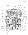
- the setpoint adjustment device is fastened with a head piece 2 in a bore in a housing 1 of a thermostatically controlled mixing valve, which is shown in part.
- the head piece 2 is screwed tightly into the housing 1 by means of a thread and an O-ring.
- a thread 31 is formed on the projecting part of the head piece 2, on which an adjusting nut 3 is axially displaceable by a rotary movement.
- a pressure pin 32 is formed concentrically in the cup-shaped adjusting nut 3 and acts on a valve rod 25 via an overload safety device 23 arranged in a bore 24.
- the valve rod 25 is connected via an expansion element to a double seat valve body for regulating the inflow cross sections of cold and hot water.
- the expansion element and the double seat valve body is not shown in the drawing.
- the adjusting nut 3 is connected with its outer casing to a grip hood 5 via its shoulder 54 by means of serration 34 in a rotationally fixed but axially displaceable manner.
- a stop ring 4 is connected non-rotatably coaxially on the head piece 2 by means of a serration 42.
- the stop ring 4 has a transverse slot 43, into which a locking bar 7 with its two legs 72 can be inserted.
- the locking bar 7 has, as can be seen in particular from FIG. 4, curved areas 71 on both legs 72 with which the clasp 7 can be locked in the plug position on the head piece 2 in an annular groove 22.
- the locking bar 7 is bent from metal wire approximately U-shaped.
- annular groove 41 is also let in on the outer jacket.
- Latch elements 6 engage in this annular groove 41 from the outside through slots 51 in the wall of the grip hood 5.
- the locking elements 6 are integrally formed as radial segments on a split ring 61 made of plastic. The ring 61 bears against the outer wall of the handle cover 5. The locking elements 6 thus cause in their plug-in position that the handle cover 5 is rotatably but axially fixed on the stop ring 4.
- a grip sleeve 8 is pushed onto the front area of the grip hood 5, which is held in the axial position on the one hand on a shoulder 52 and on the other hand by an end cap 81 which can be fastened to the grip hood 5, so that the ring 61 is attached the locking elements 6 can no longer slide radially out of the annular groove 41.
- the handle cover 5 By turning the handle cover 5, the rotary movement via the shoulder 54 and the serration 34 is transmitted to the adjusting nut 3, which in turn is correspondingly axially displaced via the thread 31 to the head piece 2 and the housing 1 of the mixing valve and thus an adjusting movement on the valve rod 25 transmits.
- the locking bar 7 with the transverse slot 43 is covered by the outer surface of the handle cover 5 in the inserted position.
- the handle cover 5 is thus securely held against relatively high axial forces with the locking bar 7 and the locking elements 6, neither the locking elements 6 nor the locking bar 7 being visible to the user from the outside.
- the end cap 81 is expediently fastened with a thread 82 to the end face of the handle cover 5, so that a simple assembly and disassembly of the setpoint adjustment device on the mixing valve is possible for the person skilled in the art. After removing the end cap 81, the grip sleeve 8 can be pulled off immediately. Thereafter, the ring 61 with the locking elements 6 can be removed radially from the slots 51 of the grip hood 5.
- the handle hood 5 can be removed from the stop ring 4 and the adjusting nut 3. Thereafter, the locking bar 7 is also accessible in the transverse slot 43 and can also be removed radially from the head piece 2. Now the stop ring 4 can also be removed axially from the head piece. The adjusting nut 3 can then be completely unscrewed from the head piece. The assembly can be done in reverse order.
Landscapes
- Engineering & Computer Science (AREA)
- Automation & Control Theory (AREA)
- Health & Medical Sciences (AREA)
- Hydrology & Water Resources (AREA)
- Public Health (AREA)
- Water Supply & Treatment (AREA)
- Physics & Mathematics (AREA)
- Life Sciences & Earth Sciences (AREA)
- General Physics & Mathematics (AREA)
- Multiple-Way Valves (AREA)
- Processing And Handling Of Plastics And Other Materials For Molding In General (AREA)
- Indication Of The Valve Opening Or Closing Status (AREA)
- Preventing Unauthorised Actuation Of Valves (AREA)
- Accessories For Mixers (AREA)
- Domestic Plumbing Installations (AREA)
- Sampling And Sample Adjustment (AREA)
Applications Claiming Priority (2)
| Application Number | Priority Date | Filing Date | Title |
|---|---|---|---|
| DE4141789 | 1991-12-18 | ||
| DE4141789A DE4141789A1 (de) | 1991-12-18 | 1991-12-18 | Stellvorrichtung fuer ein mischventil |
Publications (3)
| Publication Number | Publication Date |
|---|---|
| EP0552452A2 EP0552452A2 (de) | 1993-07-28 |
| EP0552452A3 EP0552452A3 (en) | 1993-08-25 |
| EP0552452B1 true EP0552452B1 (de) | 1995-03-08 |
Family
ID=6447371
Family Applications (1)
| Application Number | Title | Priority Date | Filing Date |
|---|---|---|---|
| EP92120901A Expired - Lifetime EP0552452B1 (de) | 1991-12-18 | 1992-12-08 | Stellvorrichtung für ein Mischventil |
Country Status (7)
| Country | Link |
|---|---|
| US (1) | US5242108A (es) |
| EP (1) | EP0552452B1 (es) |
| JP (1) | JP3280089B2 (es) |
| AT (1) | ATE119697T1 (es) |
| DE (2) | DE4141789A1 (es) |
| DK (1) | DK0552452T3 (es) |
| ES (2) | ES1023017Y (es) |
Families Citing this family (7)
| Publication number | Priority date | Publication date | Assignee | Title |
|---|---|---|---|---|
| US5356074A (en) * | 1993-11-05 | 1994-10-18 | Jacob Delafon | Thermostatic mixing device |
| DE19502147C2 (de) * | 1995-01-25 | 1997-11-27 | Ideal Standard | Sanitäre Mischbatterie mit Thermostateinrichtung |
| DE10153988B4 (de) | 2001-11-06 | 2011-07-21 | Grohe AG, 58675 | Sollwerteinstellvorrichtung an einem thermostatisch geregelten Mischventil |
| US6676024B1 (en) | 2002-09-05 | 2004-01-13 | Masco Corporation | Thermostatic valve with electronic control |
| ITBS20120043A1 (it) | 2012-03-22 | 2013-09-23 | Nuova Galatron S R L | Cartuccia termostatica e corrispondente corpo di rubinetto |
| DE102018131097A1 (de) * | 2018-12-06 | 2020-05-14 | Schaeffler Technologies AG & Co. KG | Vorrichtung zur Sicherung eines Druckausgleichsventils in einem Getriebebauteil, Druckausgleichsventil und Vorrichtung zur Regelung von Drücken eines Strömungsmittels in einem Fahrzeuggetriebe |
| DE102019128364A1 (de) * | 2019-10-21 | 2021-04-22 | Horcher Gmbh | Ventilanordnung |
Family Cites Families (9)
| Publication number | Priority date | Publication date | Assignee | Title |
|---|---|---|---|---|
| DE1164779B (de) * | 1960-05-11 | 1964-03-05 | Grohe Armaturen Friedrich | Thermostatgeregelte Durchlaufmischvorrichtung fuer Kalt- und Warmwasser mit Voreinstellung der Menge |
| FR2067762A5 (es) * | 1969-11-15 | 1971-08-20 | Queroy Ets | |
| FR2128943A5 (es) * | 1971-03-09 | 1972-10-27 | Trubert Denis | |
| SE422491B (sv) | 1978-03-03 | 1982-03-08 | Vaergaarda Armaturfab Ab | Termostatstyrd blandare for tva vetskor |
| DE3236372C2 (de) * | 1982-10-01 | 1987-04-30 | Danfoss A/S, Nordborg | Thermostataufsatz für ein Ventil |
| DE3236371C2 (de) * | 1982-10-01 | 1984-08-30 | Danfoss A/S, Nordborg | Thermostatventil |
| DE3530812A1 (de) * | 1985-08-29 | 1987-03-05 | Grohe Armaturen Friedrich | Stellvorrichtung fuer ein thermostatisch geregeltes mischventil |
| DE3543330C1 (de) | 1985-12-07 | 1986-10-09 | Honeywell-Braukmann GmbH, 6950 Mosbach | Thermostatventil |
| DE4038141C1 (es) * | 1990-11-30 | 1992-05-27 | Danfoss A/S, Nordborg, Dk |
-
1991
- 1991-12-18 DE DE4141789A patent/DE4141789A1/de not_active Withdrawn
-
1992
- 1992-10-26 JP JP28763292A patent/JP3280089B2/ja not_active Expired - Fee Related
- 1992-10-30 US US07/969,127 patent/US5242108A/en not_active Expired - Fee Related
- 1992-11-20 ES ES19929203425U patent/ES1023017Y/es not_active Expired - Fee Related
- 1992-12-08 DK DK92120901.1T patent/DK0552452T3/da active
- 1992-12-08 ES ES92120901T patent/ES2072686T3/es not_active Expired - Lifetime
- 1992-12-08 AT AT92120901T patent/ATE119697T1/de not_active IP Right Cessation
- 1992-12-08 EP EP92120901A patent/EP0552452B1/de not_active Expired - Lifetime
- 1992-12-08 DE DE59201612T patent/DE59201612D1/de not_active Expired - Fee Related
Also Published As
| Publication number | Publication date |
|---|---|
| ES1023017U (es) | 1993-06-01 |
| DE59201612D1 (de) | 1995-04-13 |
| US5242108A (en) | 1993-09-07 |
| ES1023017Y (es) | 1993-12-01 |
| EP0552452A3 (en) | 1993-08-25 |
| ES2072686T3 (es) | 1995-07-16 |
| DE4141789A1 (de) | 1993-06-24 |
| JP3280089B2 (ja) | 2002-04-30 |
| JPH06185670A (ja) | 1994-07-08 |
| ATE119697T1 (de) | 1995-03-15 |
| EP0552452A2 (de) | 1993-07-28 |
| DK0552452T3 (da) | 1995-07-31 |
Similar Documents
| Publication | Publication Date | Title |
|---|---|---|
| EP0461536B1 (de) | Sollwerteinstellvorrichtung für ein thermostatisch geregeltes Mischventil | |
| EP0530471B1 (de) | Stellvorrichtung für ein Mischventil | |
| EP1061300A2 (de) | Stellvorrichtung | |
| EP0745798B1 (de) | Stellgriff einer Sanitärarmatur | |
| EP0778434A1 (de) | Stellgriff | |
| DE2737083C2 (de) | Heizkörperventil | |
| EP1903268A2 (de) | Stellgriff für ein Wasserventil | |
| EP0552452A2 (de) | Stellvorrichtung für ein Mischventil | |
| EP0552453B1 (de) | Stellvorrichtung für ein Mischventil | |
| DE10007906A1 (de) | Thermostatgeregelte Mischbatterie | |
| DE3515752A1 (de) | Strangregulierventil | |
| DE19917780C1 (de) | Heizkörperventil-Steueraufsatz | |
| DE10030699C2 (de) | Voreinstellbares Einbauventil | |
| DE10153988A1 (de) | Stellvorrichtung für ein Mischventil | |
| DE4442402C1 (de) | Thermostatkopf für Heizungsventile | |
| DE4104656A1 (de) | Betaetigungsglied mit ueberlastsicherung | |
| DE3521965A1 (de) | Thermostat fuer heizkoerperventile | |
| EP1621951B1 (de) | Mischventil mit Stellvorrichtung | |
| DE10236572B4 (de) | Griffbefestigung bei Sanitärarmaturen | |
| DE3243552C2 (de) | Thermostatisch gesteuerte Einstellvorrichtung für Heizungsventile | |
| DE3830312C2 (es) | ||
| DE202023101161U1 (de) | Ventiloberteil für Sanitärarmaturen | |
| DE29610724U1 (de) | Auf einem Behälterstutzen befestigbarer Verschlußdeckel | |
| CH479010A (de) | Betätigungsvorrichtung mit Spindel und Handgriff, vorzugsweise für Wasser-Zapfstellenarmaturen | |
| DE202020104872U1 (de) | Wasserventil für den Sanitärbereich mit Temperaturbegrenzung |
Legal Events
| Date | Code | Title | Description |
|---|---|---|---|
| PUAI | Public reference made under article 153(3) epc to a published international application that has entered the european phase |
Free format text: ORIGINAL CODE: 0009012 |
|
| PUAL | Search report despatched |
Free format text: ORIGINAL CODE: 0009013 |
|
| AK | Designated contracting states |
Kind code of ref document: A2 Designated state(s): AT BE CH DE DK ES FR GB GR IT LI NL SE |
|
| AK | Designated contracting states |
Kind code of ref document: A3 Designated state(s): AT BE CH DE DK ES FR GB GR IT LI NL SE |
|
| 17P | Request for examination filed |
Effective date: 19931030 |
|
| 17Q | First examination report despatched |
Effective date: 19931202 |
|
| GRAA | (expected) grant |
Free format text: ORIGINAL CODE: 0009210 |
|
| AK | Designated contracting states |
Kind code of ref document: B1 Designated state(s): AT BE CH DE DK ES FR GB GR IT LI NL SE |
|
| PG25 | Lapsed in a contracting state [announced via postgrant information from national office to epo] |
Ref country code: GR Free format text: LAPSE BECAUSE OF FAILURE TO SUBMIT A TRANSLATION OF THE DESCRIPTION OR TO PAY THE FEE WITHIN THE PRESCRIBED TIME-LIMIT Effective date: 19950308 Ref country code: BE Effective date: 19950308 |
|
| REF | Corresponds to: |
Ref document number: 119697 Country of ref document: AT Date of ref document: 19950315 Kind code of ref document: T |
|
| REF | Corresponds to: |
Ref document number: 59201612 Country of ref document: DE Date of ref document: 19950413 |
|
| ET | Fr: translation filed | ||
| ITF | It: translation for a ep patent filed | ||
| GBT | Gb: translation of ep patent filed (gb section 77(6)(a)/1977) |
Effective date: 19950612 |
|
| REG | Reference to a national code |
Ref country code: ES Ref legal event code: FG2A Ref document number: 2072686 Country of ref document: ES Kind code of ref document: T3 |
|
| REG | Reference to a national code |
Ref country code: DK Ref legal event code: T3 |
|
| PLBE | No opposition filed within time limit |
Free format text: ORIGINAL CODE: 0009261 |
|
| STAA | Information on the status of an ep patent application or granted ep patent |
Free format text: STATUS: NO OPPOSITION FILED WITHIN TIME LIMIT |
|
| 26N | No opposition filed | ||
| NLT1 | Nl: modifications of names registered in virtue of documents presented to the patent office pursuant to art. 16 a, paragraph 1 |
Owner name: FRIEDRICH GROHE AG & CO. KG |
|
| REG | Reference to a national code |
Ref country code: CH Ref legal event code: PFA Free format text: FRIEDRICH GROHE AKTIENGESELLSCHAFT TRANSFER- FRIEDRICH GROHE AG & CO. KG |
|
| REG | Reference to a national code |
Ref country code: FR Ref legal event code: CJ |
|
| REG | Reference to a national code |
Ref country code: GB Ref legal event code: IF02 |
|
| PGFP | Annual fee paid to national office [announced via postgrant information from national office to epo] |
Ref country code: SE Payment date: 20031128 Year of fee payment: 12 Ref country code: NL Payment date: 20031128 Year of fee payment: 12 |
|
| PGFP | Annual fee paid to national office [announced via postgrant information from national office to epo] |
Ref country code: GB Payment date: 20031203 Year of fee payment: 12 |
|
| PGFP | Annual fee paid to national office [announced via postgrant information from national office to epo] |
Ref country code: CH Payment date: 20031211 Year of fee payment: 12 |
|
| PGFP | Annual fee paid to national office [announced via postgrant information from national office to epo] |
Ref country code: DK Payment date: 20031216 Year of fee payment: 12 |
|
| PGFP | Annual fee paid to national office [announced via postgrant information from national office to epo] |
Ref country code: AT Payment date: 20031229 Year of fee payment: 12 |
|
| PGFP | Annual fee paid to national office [announced via postgrant information from national office to epo] |
Ref country code: FR Payment date: 20031230 Year of fee payment: 12 Ref country code: ES Payment date: 20031230 Year of fee payment: 12 |
|
| PG25 | Lapsed in a contracting state [announced via postgrant information from national office to epo] |
Ref country code: GB Free format text: LAPSE BECAUSE OF NON-PAYMENT OF DUE FEES Effective date: 20041208 Ref country code: AT Free format text: LAPSE BECAUSE OF NON-PAYMENT OF DUE FEES Effective date: 20041208 |
|
| PG25 | Lapsed in a contracting state [announced via postgrant information from national office to epo] |
Ref country code: SE Free format text: LAPSE BECAUSE OF NON-PAYMENT OF DUE FEES Effective date: 20041209 Ref country code: ES Free format text: LAPSE BECAUSE OF NON-PAYMENT OF DUE FEES Effective date: 20041209 |
|
| PG25 | Lapsed in a contracting state [announced via postgrant information from national office to epo] |
Ref country code: LI Free format text: LAPSE BECAUSE OF NON-PAYMENT OF DUE FEES Effective date: 20041231 Ref country code: CH Free format text: LAPSE BECAUSE OF NON-PAYMENT OF DUE FEES Effective date: 20041231 |
|
| PG25 | Lapsed in a contracting state [announced via postgrant information from national office to epo] |
Ref country code: DK Free format text: LAPSE BECAUSE OF NON-PAYMENT OF DUE FEES Effective date: 20050103 |
|
| PG25 | Lapsed in a contracting state [announced via postgrant information from national office to epo] |
Ref country code: NL Free format text: LAPSE BECAUSE OF NON-PAYMENT OF DUE FEES Effective date: 20050701 |
|
| REG | Reference to a national code |
Ref country code: DK Ref legal event code: EBP |
|
| GBPC | Gb: european patent ceased through non-payment of renewal fee |
Effective date: 20041208 |
|
| EUG | Se: european patent has lapsed | ||
| REG | Reference to a national code |
Ref country code: CH Ref legal event code: PL |
|
| PG25 | Lapsed in a contracting state [announced via postgrant information from national office to epo] |
Ref country code: FR Free format text: LAPSE BECAUSE OF NON-PAYMENT OF DUE FEES Effective date: 20050831 |
|
| NLV4 | Nl: lapsed or anulled due to non-payment of the annual fee |
Effective date: 20050701 |
|
| REG | Reference to a national code |
Ref country code: FR Ref legal event code: ST |
|
| PG25 | Lapsed in a contracting state [announced via postgrant information from national office to epo] |
Ref country code: IT Free format text: LAPSE BECAUSE OF NON-PAYMENT OF DUE FEES;WARNING: LAPSES OF ITALIAN PATENTS WITH EFFECTIVE DATE BEFORE 2007 MAY HAVE OCCURRED AT ANY TIME BEFORE 2007. THE CORRECT EFFECTIVE DATE MAY BE DIFFERENT FROM THE ONE RECORDED. Effective date: 20051208 |
|
| REG | Reference to a national code |
Ref country code: ES Ref legal event code: FD2A Effective date: 20041209 |
|
| PGFP | Annual fee paid to national office [announced via postgrant information from national office to epo] |
Ref country code: DE Payment date: 20061211 Year of fee payment: 15 |
|
| PG25 | Lapsed in a contracting state [announced via postgrant information from national office to epo] |
Ref country code: DE Free format text: LAPSE BECAUSE OF NON-PAYMENT OF DUE FEES Effective date: 20080701 |