EP0550887B1 - Memory circuit for spatial light modulator - Google Patents
Memory circuit for spatial light modulator Download PDFInfo
- Publication number
- EP0550887B1 EP0550887B1 EP92121927A EP92121927A EP0550887B1 EP 0550887 B1 EP0550887 B1 EP 0550887B1 EP 92121927 A EP92121927 A EP 92121927A EP 92121927 A EP92121927 A EP 92121927A EP 0550887 B1 EP0550887 B1 EP 0550887B1
- Authority
- EP
- European Patent Office
- Prior art keywords
- memory cell
- array
- memory cells
- voltage level
- row
- Prior art date
- Legal status (The legal status is an assumption and is not a legal conclusion. Google has not performed a legal analysis and makes no representation as to the accuracy of the status listed.)
- Expired - Lifetime
Links
Images


Classifications
-
- G—PHYSICS
- G02—OPTICS
- G02F—OPTICAL DEVICES OR ARRANGEMENTS FOR THE CONTROL OF LIGHT BY MODIFICATION OF THE OPTICAL PROPERTIES OF THE MEDIA OF THE ELEMENTS INVOLVED THEREIN; NON-LINEAR OPTICS; FREQUENCY-CHANGING OF LIGHT; OPTICAL LOGIC ELEMENTS; OPTICAL ANALOGUE/DIGITAL CONVERTERS
- G02F2/00—Demodulating light; Transferring the modulation of modulated light; Frequency-changing of light
-
- G—PHYSICS
- G09—EDUCATION; CRYPTOGRAPHY; DISPLAY; ADVERTISING; SEALS
- G09G—ARRANGEMENTS OR CIRCUITS FOR CONTROL OF INDICATING DEVICES USING STATIC MEANS TO PRESENT VARIABLE INFORMATION
- G09G3/00—Control arrangements or circuits, of interest only in connection with visual indicators other than cathode-ray tubes
- G09G3/20—Control arrangements or circuits, of interest only in connection with visual indicators other than cathode-ray tubes for presentation of an assembly of a number of characters, e.g. a page, by composing the assembly by combination of individual elements arranged in a matrix no fixed position being assigned to or needed to be assigned to the individual characters or partial characters
- G09G3/34—Control arrangements or circuits, of interest only in connection with visual indicators other than cathode-ray tubes for presentation of an assembly of a number of characters, e.g. a page, by composing the assembly by combination of individual elements arranged in a matrix no fixed position being assigned to or needed to be assigned to the individual characters or partial characters by control of light from an independent source
- G09G3/3433—Control arrangements or circuits, of interest only in connection with visual indicators other than cathode-ray tubes for presentation of an assembly of a number of characters, e.g. a page, by composing the assembly by combination of individual elements arranged in a matrix no fixed position being assigned to or needed to be assigned to the individual characters or partial characters by control of light from an independent source using light modulating elements actuated by an electric field and being other than liquid crystal devices and electrochromic devices
- G09G3/346—Control arrangements or circuits, of interest only in connection with visual indicators other than cathode-ray tubes for presentation of an assembly of a number of characters, e.g. a page, by composing the assembly by combination of individual elements arranged in a matrix no fixed position being assigned to or needed to be assigned to the individual characters or partial characters by control of light from an independent source using light modulating elements actuated by an electric field and being other than liquid crystal devices and electrochromic devices based on modulation of the reflection angle, e.g. micromirrors
-
- G—PHYSICS
- G02—OPTICS
- G02B—OPTICAL ELEMENTS, SYSTEMS OR APPARATUS
- G02B26/00—Optical devices or arrangements for the control of light using movable or deformable optical elements
- G02B26/08—Optical devices or arrangements for the control of light using movable or deformable optical elements for controlling the direction of light
- G02B26/0816—Optical devices or arrangements for the control of light using movable or deformable optical elements for controlling the direction of light by means of one or more reflecting elements
- G02B26/0833—Optical devices or arrangements for the control of light using movable or deformable optical elements for controlling the direction of light by means of one or more reflecting elements the reflecting element being a micromechanical device, e.g. a MEMS mirror, DMD
- G02B26/0841—Optical devices or arrangements for the control of light using movable or deformable optical elements for controlling the direction of light by means of one or more reflecting elements the reflecting element being a micromechanical device, e.g. a MEMS mirror, DMD the reflecting element being moved or deformed by electrostatic means
-
- G—PHYSICS
- G09—EDUCATION; CRYPTOGRAPHY; DISPLAY; ADVERTISING; SEALS
- G09F—DISPLAYING; ADVERTISING; SIGNS; LABELS OR NAME-PLATES; SEALS
- G09F9/00—Indicating arrangements for variable information in which the information is built-up on a support by selection or combination of individual elements
- G09F9/30—Indicating arrangements for variable information in which the information is built-up on a support by selection or combination of individual elements in which the desired character or characters are formed by combining individual elements
- G09F9/37—Indicating arrangements for variable information in which the information is built-up on a support by selection or combination of individual elements in which the desired character or characters are formed by combining individual elements being movable elements
- G09F9/372—Indicating arrangements for variable information in which the information is built-up on a support by selection or combination of individual elements in which the desired character or characters are formed by combining individual elements being movable elements the positions of the elements being controlled by the application of an electric field
-
- H—ELECTRICITY
- H04—ELECTRIC COMMUNICATION TECHNIQUE
- H04N—PICTORIAL COMMUNICATION, e.g. TELEVISION
- H04N3/00—Scanning details of television systems; Combination thereof with generation of supply voltages
- H04N3/10—Scanning details of television systems; Combination thereof with generation of supply voltages by means not exclusively optical-mechanical
- H04N3/12—Scanning details of television systems; Combination thereof with generation of supply voltages by means not exclusively optical-mechanical by switched stationary formation of lamps, photocells or light relays
-
- H—ELECTRICITY
- H04—ELECTRIC COMMUNICATION TECHNIQUE
- H04N—PICTORIAL COMMUNICATION, e.g. TELEVISION
- H04N5/00—Details of television systems
- H04N5/74—Projection arrangements for image reproduction, e.g. using eidophor
- H04N5/7416—Projection arrangements for image reproduction, e.g. using eidophor involving the use of a spatial light modulator, e.g. a light valve, controlled by a video signal
- H04N5/7458—Projection arrangements for image reproduction, e.g. using eidophor involving the use of a spatial light modulator, e.g. a light valve, controlled by a video signal the modulator being an array of deformable mirrors, e.g. digital micromirror device [DMD]
-
- G—PHYSICS
- G09—EDUCATION; CRYPTOGRAPHY; DISPLAY; ADVERTISING; SEALS
- G09G—ARRANGEMENTS OR CIRCUITS FOR CONTROL OF INDICATING DEVICES USING STATIC MEANS TO PRESENT VARIABLE INFORMATION
- G09G2300/00—Aspects of the constitution of display devices
- G09G2300/08—Active matrix structure, i.e. with use of active elements, inclusive of non-linear two terminal elements, in the pixels together with light emitting or modulating elements
- G09G2300/0809—Several active elements per pixel in active matrix panels
- G09G2300/0842—Several active elements per pixel in active matrix panels forming a memory circuit, e.g. a dynamic memory with one capacitor
- G09G2300/0857—Static memory circuit, e.g. flip-flop
-
- G—PHYSICS
- G09—EDUCATION; CRYPTOGRAPHY; DISPLAY; ADVERTISING; SEALS
- G09G—ARRANGEMENTS OR CIRCUITS FOR CONTROL OF INDICATING DEVICES USING STATIC MEANS TO PRESENT VARIABLE INFORMATION
- G09G2310/00—Command of the display device
- G09G2310/02—Addressing, scanning or driving the display screen or processing steps related thereto
- G09G2310/0264—Details of driving circuits
- G09G2310/0289—Details of voltage level shifters arranged for use in a driving circuit
Definitions
- This invention relates to a spatial light modulator system as defined in the precharacterizing part of claim 1. Moreover, it relates to a method of addressing an array of memory cells used to operate a spatial light modulator.
- SLM's Spatial light modulators
- the incident light may be modulated in phase, intensity, polarization, or direction.
- the light modulation may be achieved by a variety of materials exhibiting various electro-optic or magneto-optic effects and by materials that modulate light by surface deformation.
- SLM's have found numerous applications in the areas of optical information processing, projection displays, and electrostatic printing.
- SLM data storage on a per pixel basis.
- SLM's take the place of raster-scan electron beam devices.
- the SLM is comprised of an area array of individually addressable pixel elements, each of which corresponds to a point of an image.
- light from each pixel element is magnified and projected to a display screen by an optical system.
- the type of modulation depends on how the modulator is combined with an optical system.
- each pixel is addressed and data pertaining to its desired state is loaded into a memory cell associated with that pixel. Then, the pixels change state to produce an image.
- DMD deformable mirror device
- each pixel element is a tiny mirror, each capable of separate mechanical movement in response to an electrical input.
- Incident light may be modulated in direction, phase, or amplitude by reflection from each pixel element.
- Various DMD architectures have been developed, which include variations with respect to the type of mirror elements and the addressing circuit.
- Mirror element types include elastomer, membrane, and cantilever or torsion beam types. Addressing may be by e-beam input, optically, or by means of an electronic memory circuit.
- Cantilever and torsion beam architectures, in combination with integrated circuit addressing are described in a article entitled "Deformable-Mirror Spatial Light Modulators", by Larry J.
- a problem with dynamic memory designs is that relatively large storage capacitors are required at the cell site. When used in an SLM integrated circuit, these capacitors are susceptible to interlayer dielectric effects. Also, bi-stable SLM pixel designs require both signal polarities at the pixel site. To accomplish this bi-polarity with DRAM memory cells, either two drive lines and associated storage capacitors are required, or an inverter must be added to each cell. Finally, applications for SLM's involve illumination of the SLM, and as illumination increases, the refresh requirements of DRAM cells due to the charge carriers generated by illumination increases.
- SRAM static random access memory
- the spatial light modulator system as defined above is provided with the features of the characterizing part of claim 1.
- each static memory cell resembles the cell of conventional static random access memory architectures.
- each of the memory cells may be a latch, and more specifically, may be comprised of a pair of cross-coupled inverters.
- a technical advantage of the invention is that the SRAM-based design avoids the refresh requirements of DRAM based designs.
- the SHAM design is much less sensitive to illumination-generated charge carriers.
- the SRAM cells are also immune to degradation of addressing voltage by charge sharing of capacitors with the SLM elements or to body effect losses of transistors.
- the SRAM design permits non-destructive read-back -- the cells can be read back any number of times without affecting the cell contents.
- SRAM circuit designs may be used, which eliminates the need to design and test new circuits and fabrication techniques.
- the invention is amenable to integrated circuit fabrication, and may be easily implemented as sublayers of the SLM.
- the invention is especially useful in the case of cantilever or torsion-beam SLM designs, whose elements are micro-mechanical mirrors.
- the two-level power supply permits sufficient voltage for tilting the mirror elements while not hampering write operations.
- This voltage may be tailored to meet the needs of the particular mirror element architecture, an important feature in that the voltage requirements of different architectures cover a broad range of voltages, typically 5 to 10 volts.
- the voltage may be lowered to the minimum required for that purpose, which is typically lower than that required for tilting the mirrors. This prevents large current spikes during writing, and permits writing to be achieved at faster rates.
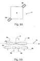
- Figures 2A and 2B illustrate a moveable modulating element, such as might be used in the SLM array of Figure 1.
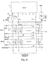
- Figure 3 illustrates the addressing circuit for the array of Figure 1.
- Figure 4 illustrates an isolation switch and pull-up transistor, such as are associated with each column, and a single memory cell for that column.
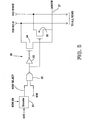
- Figure 5 illustrates a level shifter circuit for shifting the voltage into each memory cell.
- FIG. 1 illustrates a spatial light modulator (SLM) array and its peripheral memory loading circuitry.
- SLM spatial light modulator
- SLM's have an array 10 of individually addressable, micro-mechanical, elements.
- SLM will be described in terms of a deformable mirror device (DMD), whose modulating elements are mirrors that deform by some sort of deflection or tilting movement.
- DMD deformable mirror device
- each element is addressed with at least one pair of address electrodes, which bias the mirror and cause its movement.
- a memory cell associated with each pixel element stores data that determines its movement.
- the invention is useful for any type of SLM having micro-mechanical elements that are electrically addressable and have associated memory cells.
- array 10 is a 640 x 480 element array.
- the concepts described herein could be implemented with any size array, with appropriate changes being made to the data widths described herein.
- array 10 has an input unit 11, comprised of a shift register circuit 12, latch circuit 13, and column driver circuit 14.
- array 10 receives data into 40 16-bit shift registers of shift register circuit 12. For a 640-column image, after 16 clock cycles, an entire display row is stored in shift register circuit 12.
- Shift register circuit 12 is controlled by a clock signal (CLK).
- shift register circuit 12 After shift register circuit 12 is loaded, it transfers its row of data to latch circuit 13. While data is latched and is subsequently being stored in a selected row of array 10, a next row of data may be loaded into shift register circuit 12.
- Latch circuit 13 is controlled by load, set, and reset signals (LD, PSET, and PRESET).
- Column driver circuit 14 drives 1 bit of row data to each column of array 10 along 640 bit-lines.
- Additional logic may be added to input unit 11 for reading data out of the memory cells.
- the read back function is primarily used for electrical test.
- Array 10 is also in communication with a row selector unit 15.
- row selector 15 is comprised of decoders, one each associated with each row of array 10. Each decoder receives 8 bits of address data (ADD), which represent a row whose memory is to be loaded. Row selector 15 also receives a row enable signal (EN) and a read/write signal (R/W).
- ADD address data
- R/W read/write signal
- Figures 2A and 2B illustrate a movable pixel element 21, such as the modulating elements that comprise array 10.
- the pixel element 21 of Figures 2A and 2B is of a torsion-beam design, where a thick reflective beam, i.e., mirror 22, is suspended over an air gap and connected between two rigid supports by two thin torsion hinges 23a and 23b that are under tension.
- an address electrode 24a or 24b underlying one-half of mirror 22, is energized, an attractive force is applied to that portion of mirror 22, causing torsion hinges 23a and 23b to twist and mirror 22 to rotate about the axis of hinges 23a and 23b.
- mirror 22 moves about an axis from the position shown by the dotted line 25a to the position shown by the dotted line 25b relative to the plane surface 25c of mirror 22. In an "on" position, the edge of mirror 22 touches landing electrode 26a. Mirror 22 is moved to the "on” position by applying the proper voltages to address electrodes 24a and 24b. An added bias may be applied to mirror 22 through electrode 27. If an opposite voltage is applied to electrodes 24a and 24b, then mirror 22 will rotate to the position represented by the dotted line 25b and direct the light elsewhere.
- the torsion-beam pixel of Figures 2A and 2B is only one type of modulating element structure, and many other structures are possible. These are distinguished by characteristics such as their deformation mode, pixel shape, and the hinge support means. However, for purposes of the invention herein, any sort of structure is satisfactory so long as each modulating element is capable of independent movement as a result of energizing its address electrodes.
- Figure 3 illustrates the memory loading circuit of Figure 1 in relation to the memory cell array 30 associated with the modulating element array 10. Only the top two rows of memory cell array 30 are shown; it should be understood that a complete array 30 would include a memory call 32 for each modulating element 21.
- Figure 3 is a simplified embodiment in that each modulating element 21 has only one memory cell 32; other embodiments might have more than one memory cell 32 per modulating element 21.
- memory cell array 30 receives data input (DATA) from input unit 11, via an input line 31 for each column. As described above, for each DATA input along input line 31, latch circuit 13 holds the data during the time for driving it to the memory cells 32 of that column.
- DATA data input
- each input line 31 runs to write buffer 33, and then to isolation switch 34.
- Another input to isolation switch 34 is a R/W signal. Isolation switch 34 is explained below in connection with Figure 4.
- Pull-up transistor 35 is always “on” and pulls the voltage on bit-line 31a toward a desired voltage, VDD.
- VDD is 5 volts.
- the DATA signal on each bit-line 31a is input to a column of memory cell array 30.
- the ROW line into each cell 32 is analogous to a memory word line.
- Each memory cell 32 receives input from a two-level voltage supply line, VH/VW line 37.
- a first level, VW is used while the memory cells 32 of a row are being written.
- another level, VH typically a higher voltage of 5 - 8 volts, is used to vary the voltage at the address electrodes 24a and 24b of the modulating elements 21, to tilt them in a desired direction.
- a level shifter circuit for shifting between these voltages is explained below in connection with Figure 5.
- the VSS line 38 is to a common level, and in this example, is to circuit ground.
- An advantage of the invention especially when used with cantilever-beam or torsion-beam SLM's, is that the second voltage level, VH, which is used for operating the modulating elements 21, may be tailored to match their mechanical compliance.
- the threshold voltage for deflecting the mirror element 21 can be determined, and VH matched to that level. This reduces the need for additional biasing for the modulating elements 21 from a separate source.
- both voltage polarities of the mirror deflection voltage may be easily made available.
- VH voltage supply is delivered along an additional VH line 39 across each row of array 30.
- the purpose of VH line 39 is to provide a VH supply to N-wells in the silicon, which permits the VH voltage level to reach each memory cell 32 in the row without substantial loss of voltage.
- each VSS line 38 and VH line 39 across array 30 is shared by two rows of memory cells 32. This economizes on space and materials.
- output lines 11a could be connected to bit-line 31a below isolation switch 34.
- An output unit 11b having control and timing logic would control when data on these lines 11a are available for read back.
- FIG. 4 illustrates an isolation switch 34, pull-up transistor 35, such as are associated with each column of array 30, as well as a single memory cell 32 for that column.
- M* Various transistors in both circuits are referred to as "M*" where * designates a transistor number.
- each transistor is an insulated gate field effect transistor.
- Transistors M2, M3, M5, and M7 are p-channel transistors; transistors, M4, M6, M8, and M9 are n-channel transistors.
- the capacitances, C1 and C2 represent the capacitive loads presented to memory cell 32 by the modulating element 21.
- Isolation switch 34 is comprised of two transistors, M2 and M4, which cut off input unit 11 from memory array 30.
- the signals, phase isolate (ISO) and its complement (IBAR) activate switch 34, and are applied synchronized in time and of opposite polarity.
- the transistors M2 and M4 maximize the voltage swing that can be passed by switch 34.
- Memory cell 32 is comprised of an access transistor M9 and a latch 32a, which is the basis of the static random access memory (SRAM) design. All access transistors M9 in a row receive a DATA signal from a different bit-line 31a. The particular memory cell 32 to be written is accessed by turning on the appropriate row select transistor M9, using the ROW signal.
- SRAM static random access memory
- latch 32a is formed from two cross-coupled inverters, M5/M6 and M7/M8, which permit two stable states.
- nodes A and B represent electrodes 24a and 24b of a modulating element 21
- state 1 is Node A high and Node B low
- state 2 is Node A low and Node B high.
- These states are stable in the absence of a disturbing voltage at Node A. This disturbing voltage is present at node A when it is desired to change the contents of the latch 32a.
- the two stable states are desirable for delivering both signal polarities to modulating elements 21.
- FIG. 5 illustrates a level shifter 50 for shifting the voltage on a VH/VW line 37 between the voltage level used for writing to memory (VW) and the value used for operating the modulating elements 21 (VH).
- Each row of array 10 has a level shifter circuit 50.
- each row of array 10 has a decoder unit 51, which decodes address data and if enabled by a row enable signal, ROW EN, provides a ROW SELECT signal to its row.
- the ROW SELECT signal is also delivered to NAND gate 52, as well as a R/W signal.
- the R/W signal is a global signal, and if true, its input, combined with a true input on ROW SELECT causes NAND gate 52 to output a low signal.
- a low output from NAND gate 52 turns on pass transistor 55 and causes the lower VDD WRITE voltage level to be connected to VH/VW line 37.
- a high output from NAND gate 52 causes the higher VDD HOLD voltage level to be connected to VH/VW line 37 via inverter 53 and pass transistor 54. In this manner, each row receives the lower VW voltage only while it is being written, and during this time, all other rows receive the higher VH voltage.
- NAND gate 52 and inverter 53 are in electrical connection with the higher voltage source, VDD HOLD.
- Pass transistors 54 and 55 are p-channel transistors that operate in a complementary manner.
Applications Claiming Priority (2)
| Application Number | Priority Date | Filing Date | Title |
|---|---|---|---|
| US07/815,441 US5285407A (en) | 1991-12-31 | 1991-12-31 | Memory circuit for spatial light modulator |
| US815441 | 1991-12-31 |
Publications (2)
| Publication Number | Publication Date |
|---|---|
| EP0550887A1 EP0550887A1 (en) | 1993-07-14 |
| EP0550887B1 true EP0550887B1 (en) | 1996-07-31 |
Family
ID=25217793
Family Applications (1)
| Application Number | Title | Priority Date | Filing Date |
|---|---|---|---|
| EP92121927A Expired - Lifetime EP0550887B1 (en) | 1991-12-31 | 1992-12-23 | Memory circuit for spatial light modulator |
Country Status (7)
| Country | Link |
|---|---|
| US (1) | US5285407A (ko) |
| EP (1) | EP0550887B1 (ko) |
| JP (1) | JPH06124341A (ko) |
| KR (1) | KR100284017B1 (ko) |
| CA (1) | CA2086464A1 (ko) |
| DE (1) | DE69212586T2 (ko) |
| TW (1) | TW221536B (ko) |
Families Citing this family (85)
| Publication number | Priority date | Publication date | Assignee | Title |
|---|---|---|---|---|
| US6219015B1 (en) | 1992-04-28 | 2001-04-17 | The Board Of Directors Of The Leland Stanford, Junior University | Method and apparatus for using an array of grating light valves to produce multicolor optical images |
| US5461411A (en) * | 1993-03-29 | 1995-10-24 | Texas Instruments Incorporated | Process and architecture for digital micromirror printer |
| US5680156A (en) * | 1994-11-02 | 1997-10-21 | Texas Instruments Incorporated | Memory architecture for reformatting and storing display data in standard TV and HDTV systems |
| EP0709822A3 (en) * | 1994-10-31 | 1996-07-31 | Texas Instruments Inc | Improvements in or in connection with a data formatting device and frame memories |
| US5687130A (en) * | 1994-11-30 | 1997-11-11 | Texas Instruments Incorporated | Memory cell with single bit line read back |
| US5670977A (en) * | 1995-02-16 | 1997-09-23 | Texas Instruments Incorporated | Spatial light modulator having single bit-line dual-latch memory cells |
| JP3209877B2 (ja) * | 1995-03-31 | 2001-09-17 | アルプス電気株式会社 | 光学読み取り装置 |
| US5841579A (en) | 1995-06-07 | 1998-11-24 | Silicon Light Machines | Flat diffraction grating light valve |
| US6046840A (en) * | 1995-06-19 | 2000-04-04 | Reflectivity, Inc. | Double substrate reflective spatial light modulator with self-limiting micro-mechanical elements |
| US5602785A (en) * | 1995-12-13 | 1997-02-11 | Micron Technology, Inc. | P-channel sense amplifier pull-up circuit with a timed pulse for use in DRAM memories having non-bootstrapped word lines |
| US5793383A (en) * | 1996-05-31 | 1998-08-11 | Townsend And Townsend And Crew Llp | Shared bootstrap circuit |
| US6115083A (en) * | 1996-11-08 | 2000-09-05 | Texas Instruments Incorporated | Load/reset sequence controller for spatial light modulator |
| US5982553A (en) | 1997-03-20 | 1999-11-09 | Silicon Light Machines | Display device incorporating one-dimensional grating light-valve array |
| US6480177B2 (en) | 1997-06-04 | 2002-11-12 | Texas Instruments Incorporated | Blocked stepped address voltage for micromechanical devices |
| US6088102A (en) | 1997-10-31 | 2000-07-11 | Silicon Light Machines | Display apparatus including grating light-valve array and interferometric optical system |
| US6271808B1 (en) | 1998-06-05 | 2001-08-07 | Silicon Light Machines | Stereo head mounted display using a single display device |
| US6130770A (en) | 1998-06-23 | 2000-10-10 | Silicon Light Machines | Electron gun activated grating light valve |
| US6101036A (en) | 1998-06-23 | 2000-08-08 | Silicon Light Machines | Embossed diffraction grating alone and in combination with changeable image display |
| US6215579B1 (en) | 1998-06-24 | 2001-04-10 | Silicon Light Machines | Method and apparatus for modulating an incident light beam for forming a two-dimensional image |
| US6303986B1 (en) | 1998-07-29 | 2001-10-16 | Silicon Light Machines | Method of and apparatus for sealing an hermetic lid to a semiconductor die |
| US7099065B2 (en) * | 2000-08-03 | 2006-08-29 | Reflectivity, Inc. | Micromirrors with OFF-angle electrodes and stops |
| JP4132654B2 (ja) | 2000-12-18 | 2008-08-13 | 株式会社ルネサステクノロジ | 表示制御装置および携帯用電子機器 |
| US6906850B2 (en) * | 2000-12-28 | 2005-06-14 | Texas Instruments Incorporated | Capacitively coupled micromirror |
| US6788981B2 (en) * | 2001-02-07 | 2004-09-07 | Movaz Networks, Inc. | Multiplexed analog control system for electrostatic actuator array |
| US6782205B2 (en) | 2001-06-25 | 2004-08-24 | Silicon Light Machines | Method and apparatus for dynamic equalization in wavelength division multiplexing |
| US6747781B2 (en) | 2001-06-25 | 2004-06-08 | Silicon Light Machines, Inc. | Method, apparatus, and diffuser for reducing laser speckle |
| US6829092B2 (en) | 2001-08-15 | 2004-12-07 | Silicon Light Machines, Inc. | Blazed grating light valve |
| JP2003121732A (ja) * | 2001-10-18 | 2003-04-23 | Minolta Co Ltd | デジタルカメラ |
| US7158180B2 (en) * | 2001-12-31 | 2007-01-02 | Texas Instruments Incorporated | System and method for varying exposure time for different parts of a field of view while acquiring an image |
| US6800238B1 (en) | 2002-01-15 | 2004-10-05 | Silicon Light Machines, Inc. | Method for domain patterning in low coercive field ferroelectrics |
| US6767751B2 (en) | 2002-05-28 | 2004-07-27 | Silicon Light Machines, Inc. | Integrated driver process flow |
| US6822797B1 (en) | 2002-05-31 | 2004-11-23 | Silicon Light Machines, Inc. | Light modulator structure for producing high-contrast operation using zero-order light |
| US6829258B1 (en) | 2002-06-26 | 2004-12-07 | Silicon Light Machines, Inc. | Rapidly tunable external cavity laser |
| US6813059B2 (en) | 2002-06-28 | 2004-11-02 | Silicon Light Machines, Inc. | Reduced formation of asperities in contact micro-structures |
| US6714337B1 (en) | 2002-06-28 | 2004-03-30 | Silicon Light Machines | Method and device for modulating a light beam and having an improved gamma response |
| US7057795B2 (en) * | 2002-08-20 | 2006-06-06 | Silicon Light Machines Corporation | Micro-structures with individually addressable ribbon pairs |
| US6801354B1 (en) | 2002-08-20 | 2004-10-05 | Silicon Light Machines, Inc. | 2-D diffraction grating for substantially eliminating polarization dependent losses |
| US6712480B1 (en) | 2002-09-27 | 2004-03-30 | Silicon Light Machines | Controlled curvature of stressed micro-structures |
| US6806997B1 (en) | 2003-02-28 | 2004-10-19 | Silicon Light Machines, Inc. | Patterned diffractive light modulator ribbon for PDL reduction |
| US6829077B1 (en) | 2003-02-28 | 2004-12-07 | Silicon Light Machines, Inc. | Diffractive light modulator with dynamically rotatable diffraction plane |
| US7129925B2 (en) * | 2003-04-24 | 2006-10-31 | Hewlett-Packard Development Company, L.P. | Dynamic self-refresh display memory |
| US7957050B2 (en) | 2003-11-01 | 2011-06-07 | Silicon Quest Kabushiki-Kaisha | Mirror device comprising layered electrode |
| US20090207324A1 (en) * | 2003-11-01 | 2009-08-20 | Naoya Sugimoto | Circuit for SLM's pixel |
| US7916381B2 (en) | 2003-11-01 | 2011-03-29 | Silicon Quest Kabushiki-Kaisha | Spatial light modulator including drive lines |
| US20090207164A1 (en) * | 2003-11-01 | 2009-08-20 | Naoya Sugimoto | Mirror control within time slot for SLM |
| US8154474B2 (en) * | 2003-11-01 | 2012-04-10 | Silicon Quest Kabushiki Kaisha | Driving method of memory access |
| US7969395B2 (en) | 2003-11-01 | 2011-06-28 | Silicon Quest Kabushiki-Kaisha | Spatial light modulator and mirror device |
| US20090207325A1 (en) * | 2003-11-01 | 2009-08-20 | Naoya Sugimoto | Algorithm for SLM of single hinge type |
| US20080074562A1 (en) * | 2003-11-01 | 2008-03-27 | Taro Endo | Display system comprising a mirror device with oscillation state |
| US7948505B2 (en) | 2003-11-01 | 2011-05-24 | Silicon Quest Kabushiki-Kaisha | Method for reducing temporal artifacts in digital video systems |
| US20100079685A1 (en) * | 2003-11-01 | 2010-04-01 | Taro Endo | Spatial light modulator performing a gamma correction |
| US20090195858A1 (en) * | 2003-11-01 | 2009-08-06 | Naoya Sugimoto | Changing an electrode function |
| US20090180038A1 (en) * | 2003-11-01 | 2009-07-16 | Naoya Sugimoto | Mirror control within time slot for SLM |
| US7733558B2 (en) * | 2003-11-01 | 2010-06-08 | Silicon Quest Kabushiki-Kaisha | Display device with an addressable movable electrode |
| US8228595B2 (en) * | 2003-11-01 | 2012-07-24 | Silicon Quest Kabushiki-Kaisha | Sequence and timing control of writing and rewriting pixel memories with substantially lower data rate |
| US8061854B2 (en) * | 2003-11-01 | 2011-11-22 | Silicon Quest Kabushiki-Kaisha | Projection display system with varying light source |
| US8432341B2 (en) * | 2003-11-01 | 2013-04-30 | Silicon Quest Kabushiki-Kaisha | Color sequence control for video display apparatus |
| US7969640B2 (en) * | 2003-11-01 | 2011-06-28 | Silicon Quest Kabushiki-Kaisha | Color display system |
| US8081371B2 (en) * | 2003-11-01 | 2011-12-20 | Silicon Quest Kabushiki-Kaisha | Spatial light modulator and display apparatus |
| US7973994B2 (en) * | 2003-11-01 | 2011-07-05 | Silicon Quest Kabushiki-Kaisha | Spatial light modulator |
| US8179591B2 (en) * | 2003-11-01 | 2012-05-15 | Silicon Quest Kabushiki-Kaisha | Spatial light modulator and mirror array device |
| US20050128559A1 (en) * | 2003-12-15 | 2005-06-16 | Nishimura Ken A. | Spatial light modulator and method for performing dynamic photolithography |
| US7304782B2 (en) | 2004-03-24 | 2007-12-04 | Fujifilm Corporation | Driving method of spatial light modulator array, spatial light modulator array, and image forming apparatus |
| US7019879B2 (en) * | 2004-03-26 | 2006-03-28 | Schroeder Dale W | Angled strobe lines for high aspect ratio spatial light modulator |
| US7295363B2 (en) | 2005-04-08 | 2007-11-13 | Texas Instruments Incorporated | Optical coating on light transmissive substrates of micromirror devices |
| US7826128B2 (en) * | 2005-05-23 | 2010-11-02 | Silicon Quest Kabushiki-Kaisha | Projection display system with varying light source |
| JP2007199101A (ja) | 2006-01-23 | 2007-08-09 | Fujifilm Corp | 微小電気機械素子アレイ装置及び画像形成装置 |
| US7728712B2 (en) * | 2006-03-21 | 2010-06-01 | Onestop Media Group | Digital communication system with security features |
| US7907325B2 (en) * | 2007-02-26 | 2011-03-15 | Silicon Quest Kabushiki-Kaisha | Control methods for micromirror devices implemented with a single address electrode |
| US7961161B2 (en) * | 2007-03-02 | 2011-06-14 | Silicon Quest Kabushiki-Kaisha | Display system comprising a mirror device with micromirrors controlled to operate in intermediate oscillating state |
| US20080231936A1 (en) * | 2007-03-02 | 2008-09-25 | Taro Endo | Display system comprising a mirror device with micromirrors controlled to operate in intermediate oscillating state |
| US20090128462A1 (en) * | 2007-11-16 | 2009-05-21 | Naoya Sugimoto | Spatial light modulator and mirror device |
| US20090128464A1 (en) * | 2007-11-16 | 2009-05-21 | Naoya Sugimoto | Mirror array device |
| US20090128887A1 (en) * | 2007-11-16 | 2009-05-21 | Naoya Sugimoto | Spatial light modulator and mirror array device |
| US7848005B2 (en) * | 2007-11-16 | 2010-12-07 | Silicon Quest Kabushiki-Kaisha | Spatial light modulator implemented with a mirror array device |
| US7876492B2 (en) * | 2007-11-16 | 2011-01-25 | Silicon Quest Kabushiki-Kaisha | Spatial light modulator and mirror array device |
| US20090147154A1 (en) * | 2007-12-06 | 2009-06-11 | Kazuma Arai | Color display system |
| US20090147033A1 (en) * | 2007-12-06 | 2009-06-11 | Kazuma Arai | Color display system |
| TWI404024B (zh) * | 2008-06-30 | 2013-08-01 | Innolux Corp | 畫素組、平面顯示面板及平面顯示裝置的驅動方法 |
| US20120049041A1 (en) * | 2010-09-01 | 2012-03-01 | International Business Machines Corporation | Switched rail circuitry and modified cell structure and method of manufacture and use |
| KR20130033805A (ko) * | 2011-09-27 | 2013-04-04 | 삼성디스플레이 주식회사 | 표시장치 |
| JP6104768B2 (ja) * | 2013-09-12 | 2017-03-29 | 株式会社豊田中央研究所 | 静電容量型アクチュエータアレイの駆動回路 |
| US9401200B1 (en) | 2014-12-22 | 2016-07-26 | Altera Corporation | Memory cells with p-type diffusion read-only port |
| CN108198537B (zh) * | 2018-01-03 | 2020-11-27 | 京东方科技集团股份有限公司 | 一种像素内存储单元、像素阵列及显示装置 |
| US10778945B1 (en) * | 2019-02-28 | 2020-09-15 | Texas Instruments Incorporated | Spatial light modulator with embedded pattern generation |
Family Cites Families (12)
| Publication number | Priority date | Publication date | Assignee | Title |
|---|---|---|---|---|
| JPS5916195A (ja) * | 1982-07-19 | 1984-01-27 | Toshiba Corp | 半導体記憶装置 |
| US4680579A (en) * | 1983-09-08 | 1987-07-14 | Texas Instruments Incorporated | Optical system for projection display using spatial light modulator device |
| KR930008309B1 (ko) * | 1984-02-15 | 1993-08-27 | 가부시기가이샤 다이 신꾸우 | 정전식 표시장치의 표시제어장치 |
| KR850006095A (ko) * | 1984-02-17 | 1985-09-28 | 고죠오 이꾸오 | 정전식 표시장치의 표시정보 교환장치 |
| US4642798A (en) * | 1985-10-01 | 1987-02-10 | Intel Corporation | CMOS E2 PROM decoding circuit |
| US4896297A (en) * | 1987-10-23 | 1990-01-23 | Mitsubishi Denki Kabushiki Kaisha | Circuit for generating a boosted signal for a word line |
| US4956619A (en) * | 1988-02-19 | 1990-09-11 | Texas Instruments Incorporated | Spatial light modulator |
| JP2588936B2 (ja) * | 1988-07-04 | 1997-03-12 | 沖電気工業株式会社 | 半導体記憶装置 |
| JPH0271499A (ja) * | 1988-09-06 | 1990-03-12 | Hitachi Ltd | 半導体記憶装置 |
| JPH0713880B2 (ja) * | 1988-11-21 | 1995-02-15 | 株式会社東芝 | 不揮発性半導体メモリ |
| DE69033542T2 (de) * | 1989-02-27 | 2001-01-11 | Texas Instruments Inc | Apparat und Verfahren für ein digitalisiertes Videosystem |
| US5018256A (en) * | 1990-06-29 | 1991-05-28 | Texas Instruments Incorporated | Architecture and process for integrating DMD with control circuit substrates |
-
1991
- 1991-12-31 US US07/815,441 patent/US5285407A/en not_active Expired - Lifetime
-
1992
- 1992-12-23 DE DE69212586T patent/DE69212586T2/de not_active Expired - Fee Related
- 1992-12-23 EP EP92121927A patent/EP0550887B1/en not_active Expired - Lifetime
- 1992-12-30 KR KR1019920026430A patent/KR100284017B1/ko not_active IP Right Cessation
- 1992-12-30 CA CA002086464A patent/CA2086464A1/en not_active Abandoned
-
1993
- 1993-01-04 JP JP5029568A patent/JPH06124341A/ja active Pending
- 1993-05-18 TW TW082103873A patent/TW221536B/zh active
Also Published As
| Publication number | Publication date |
|---|---|
| KR930013839A (ko) | 1993-07-22 |
| CA2086464A1 (en) | 1993-07-01 |
| KR100284017B1 (ko) | 2001-03-02 |
| EP0550887A1 (en) | 1993-07-14 |
| DE69212586D1 (de) | 1996-09-05 |
| JPH06124341A (ja) | 1994-05-06 |
| US5285407A (en) | 1994-02-08 |
| TW221536B (ko) | 1994-03-01 |
| DE69212586T2 (de) | 1997-01-30 |
Similar Documents
| Publication | Publication Date | Title |
|---|---|---|
| EP0550887B1 (en) | Memory circuit for spatial light modulator | |
| US5581272A (en) | Signal generator for controlling a spatial light modulator | |
| EP0965976B1 (en) | Liquid crystal display with pixel circuits with memories | |
| US5682174A (en) | Memory cell array for digital spatial light modulator | |
| US5612713A (en) | Digital micro-mirror device with block data loading | |
| JPH08227044A (ja) | オン状態における欠陥の可能性を減少させた空間光変調器 | |
| US7764535B2 (en) | Low power, small size SRAM architecture | |
| US6091463A (en) | Diffractive spatial light modulator | |
| EP0528490A2 (en) | Electronic matrix array devices and systems incorporating such devices | |
| US6262703B1 (en) | Pixel cell with integrated DC balance circuit | |
| JP2004327025A (ja) | ダイナミック自己リフレッシュディスプレイメモリ | |
| US6115019A (en) | Register pixel for liquid crystal displays | |
| KR100726052B1 (ko) | 전기 광학 장치 및 그의 구동 방법, 디지털 구동 액정 표시 장치, 전자 기기 및 프로젝터 | |
| US5670977A (en) | Spatial light modulator having single bit-line dual-latch memory cells | |
| US7480090B2 (en) | Optical deflecting device, optical deflecting device array, method for driving the optical deflecting device and image projection display apparatus using the device | |
| US6191883B1 (en) | Five transistor SRAM cell for small micromirror elements | |
| US4825202A (en) | Control means for an integrated memory matrix display and its control process | |
| KR100426997B1 (ko) | 단일비트라인리드백구조를갖는메모리셀 | |
| US6195301B1 (en) | Feedback driver for memory array bitline | |
| US7443716B2 (en) | Spatial light modulator with four transistor electrode driver | |
| JP2008523436A (ja) | 回転可能な双安定ディスプレイ | |
| JPH11185465A (ja) | 強誘電体メモリ | |
| KR100524904B1 (ko) | 그래픽램및그래픽램을내장한액정표시장치드라이버 | |
| JPH10134561A (ja) | 半導体メモリ |
Legal Events
| Date | Code | Title | Description |
|---|---|---|---|
| PUAI | Public reference made under article 153(3) epc to a published international application that has entered the european phase |
Free format text: ORIGINAL CODE: 0009012 |
|
| AK | Designated contracting states |
Kind code of ref document: A1 Designated state(s): DE FR GB IT NL |
|
| 17P | Request for examination filed |
Effective date: 19931119 |
|
| 17Q | First examination report despatched |
Effective date: 19950126 |
|
| GRAH | Despatch of communication of intention to grant a patent |
Free format text: ORIGINAL CODE: EPIDOS IGRA |
|
| GRAH | Despatch of communication of intention to grant a patent |
Free format text: ORIGINAL CODE: EPIDOS IGRA |
|
| GRAA | (expected) grant |
Free format text: ORIGINAL CODE: 0009210 |
|
| AK | Designated contracting states |
Kind code of ref document: B1 Designated state(s): DE FR GB IT NL |
|
| PG25 | Lapsed in a contracting state [announced via postgrant information from national office to epo] |
Ref country code: NL Free format text: LAPSE BECAUSE OF FAILURE TO SUBMIT A TRANSLATION OF THE DESCRIPTION OR TO PAY THE FEE WITHIN THE PRESCRIBED TIME-LIMIT Effective date: 19960731 Ref country code: IT Free format text: LAPSE BECAUSE OF FAILURE TO SUBMIT A TRANSLATION OF THE DESCRIPTION OR TO PAY THE FEE WITHIN THE PRESCRIBED TIME-LIMIT;WARNING: LAPSES OF ITALIAN PATENTS WITH EFFECTIVE DATE BEFORE 2007 MAY HAVE OCCURRED AT ANY TIME BEFORE 2007. THE CORRECT EFFECTIVE DATE MAY BE DIFFERENT FROM THE ONE RECORDED. Effective date: 19960731 |
|
| REF | Corresponds to: |
Ref document number: 69212586 Country of ref document: DE Date of ref document: 19960905 |
|
| ET | Fr: translation filed | ||
| NLV1 | Nl: lapsed or annulled due to failure to fulfill the requirements of art. 29p and 29m of the patents act | ||
| PLBE | No opposition filed within time limit |
Free format text: ORIGINAL CODE: 0009261 |
|
| STAA | Information on the status of an ep patent application or granted ep patent |
Free format text: STATUS: NO OPPOSITION FILED WITHIN TIME LIMIT |
|
| 26N | No opposition filed | ||
| REG | Reference to a national code |
Ref country code: GB Ref legal event code: IF02 |
|
| PGFP | Annual fee paid to national office [announced via postgrant information from national office to epo] |
Ref country code: GB Payment date: 20071106 Year of fee payment: 16 |
|
| PGFP | Annual fee paid to national office [announced via postgrant information from national office to epo] |
Ref country code: DE Payment date: 20071228 Year of fee payment: 16 |
|
| PGFP | Annual fee paid to national office [announced via postgrant information from national office to epo] |
Ref country code: FR Payment date: 20071204 Year of fee payment: 16 |
|
| GBPC | Gb: european patent ceased through non-payment of renewal fee |
Effective date: 20081223 |
|
| REG | Reference to a national code |
Ref country code: FR Ref legal event code: ST Effective date: 20090831 |
|
| PG25 | Lapsed in a contracting state [announced via postgrant information from national office to epo] |
Ref country code: DE Free format text: LAPSE BECAUSE OF NON-PAYMENT OF DUE FEES Effective date: 20090701 |
|
| PG25 | Lapsed in a contracting state [announced via postgrant information from national office to epo] |
Ref country code: GB Free format text: LAPSE BECAUSE OF NON-PAYMENT OF DUE FEES Effective date: 20081223 |
|
| PG25 | Lapsed in a contracting state [announced via postgrant information from national office to epo] |
Ref country code: FR Free format text: LAPSE BECAUSE OF NON-PAYMENT OF DUE FEES Effective date: 20081231 |