EP0550510B1 - Buse d'aeration de liquides contenant des substances organiques - Google Patents
Buse d'aeration de liquides contenant des substances organiques Download PDFInfo
- Publication number
- EP0550510B1 EP0550510B1 EP91916556A EP91916556A EP0550510B1 EP 0550510 B1 EP0550510 B1 EP 0550510B1 EP 91916556 A EP91916556 A EP 91916556A EP 91916556 A EP91916556 A EP 91916556A EP 0550510 B1 EP0550510 B1 EP 0550510B1
- Authority
- EP
- European Patent Office
- Prior art keywords
- nozzle according
- aeration nozzle
- outer sleeve
- inner sleeve
- wall
- Prior art date
- Legal status (The legal status is an assumption and is not a legal conclusion. Google has not performed a legal analysis and makes no representation as to the accuracy of the status listed.)
- Expired - Lifetime
Links
Images
Classifications
-
- B—PERFORMING OPERATIONS; TRANSPORTING
- B01—PHYSICAL OR CHEMICAL PROCESSES OR APPARATUS IN GENERAL
- B01F—MIXING, e.g. DISSOLVING, EMULSIFYING OR DISPERSING
- B01F25/00—Flow mixers; Mixers for falling materials, e.g. solid particles
- B01F25/30—Injector mixers
- B01F25/31—Injector mixers in conduits or tubes through which the main component flows
- B01F25/314—Injector mixers in conduits or tubes through which the main component flows wherein additional components are introduced at the circumference of the conduit
- B01F25/3142—Injector mixers in conduits or tubes through which the main component flows wherein additional components are introduced at the circumference of the conduit the conduit having a plurality of openings in the axial direction or in the circumferential direction
- B01F25/31425—Injector mixers in conduits or tubes through which the main component flows wherein additional components are introduced at the circumference of the conduit the conduit having a plurality of openings in the axial direction or in the circumferential direction with a plurality of perforations in the axial and circumferential direction covering the whole surface
-
- B—PERFORMING OPERATIONS; TRANSPORTING
- B01—PHYSICAL OR CHEMICAL PROCESSES OR APPARATUS IN GENERAL
- B01F—MIXING, e.g. DISSOLVING, EMULSIFYING OR DISPERSING
- B01F25/00—Flow mixers; Mixers for falling materials, e.g. solid particles
- B01F25/30—Injector mixers
- B01F25/31—Injector mixers in conduits or tubes through which the main component flows
- B01F25/314—Injector mixers in conduits or tubes through which the main component flows wherein additional components are introduced at the circumference of the conduit
- B01F25/3142—Injector mixers in conduits or tubes through which the main component flows wherein additional components are introduced at the circumference of the conduit the conduit having a plurality of openings in the axial direction or in the circumferential direction
Definitions
- the invention relates to a ventilation nozzle for aerating liquids containing organic substances with a liquid channel with at least one gas inlet opening for admixing a gas into a liquid flowing through the liquid channel and with a mixing chamber which is passed through by the liquid gas mixture which, after passing through the mixing chamber, has a pressure drop in an expansion space is expanded and the use of this ventilation nozzle for aerating wort.
- Venturi nozzle Such a ventilation nozzle is known from WO-A-90/05583.
- a so-called Venturi nozzle is used here.
- Such Venturi nozzles are designed as a tube which narrows in the form of a nozzle and then widens in a diffuser shape. If a liquid passes through a Venturi tube, the speed of the liquid is increased at an existing pressure. A negative pressure then arises. If a gas flow is supplied to the Venturi nozzle through which the liquid flows, the gas is drawn into the Venturi tube due to the negative pressure and mixed with the liquid.
- Such a ventilation nozzle is used for. B. in brewing technology for wort aeration and yeast aeration, or z. B. in filter water treatment for oxygen degassing with CO2, in the carbonization of beer and mineral water and in wastewater neutralization.
- the aeration of wort is particularly discussed. If the wort flowing into the Venturi nozzle is mixed with air, a fine distribution of the air in the wort is achieved, which has a favorable influence on the flotation effect. The finer the air bubbles are distributed in the wort, the more evenly the foam blanket is formed during flotation.
- a disadvantage of using Venturi nozzles is that large pressures occur in the Venturi tube, which make it necessary to use an additional propellant pump when large quantities of liquid flow through.
- the achievable fine distribution leaves room for improvement, and yeast aeration can also result in a lowering of the fermentation power of the yeast due to the high pressures and the narrow annular gap.
- the invention has for its object to provide a ventilation nozzle for aerating liquids containing organic substances, which enables an effective targeted generation of gas bubbles with a finer distribution in liquids than is known from the prior art .
- the liquid channel is over part of its length is surrounded by a closed annular chamber which is provided with a gas supply opening.
- a large number of the gas inlet openings are formed in the wall of the liquid channel in the area of the annular chamber. This makes it possible to distribute the gas flowing through the gas supply opening evenly around the liquid flow and to feed the gas uniformly along its entire circumference.
- the gas supply opening has a cross-sectional area of at least 1 1/2 times the size of the total gas entry area formed by the gas entry openings, an overpressure can build up in the annular chamber, by means of which the gas can penetrate into the liquid channel containing the liquid flow.
- the liquid channel and the mixing chamber hollow cylindrical, the liquid channel having an inner diameter d1 that is larger than the inner diameter d2 of the mixing chamber, the liquid channel merges into the mixing chamber with a tapered wall and the mixing chamber has a length that is at least 1 1 / 2 times the inside diameter d2 of the mixing chamber, a particularly effective, targeted and fine distribution of the gas bubbles in the liquid is achieved when the liquid gas mixture is expanded via a pressure gradient into the expansion space.
- the flotation is considerably improved, which manifests itself in a much more uniform and, above all, more compact foam blanket formation than is known from the prior art.
- the gas inlet openings are bores which have a diameter of at most one millimeter. This leads to fine gas flows enveloping the liquid flow in a network. These reticulated gas streams remain essentially on the surface of the liquid stream and move together with it over the conically tapering wall into the mixing chamber.
- the gas is mixed with the liquid in a laminar manner without the formation of turbulence, which results in a particularly uniform formation of bubbles in the liquid. It is particularly favorable 25-30 of the gas inlet openings in the wall of the liquid channel in the area of the annular chamber to train. If the distance between 2 of the gas inlet openings is at least 10 mm, the gas admixture is particularly effective.
- the conical wall forms an angle ⁇ with the axis of the outer wall of the liquid channel, which is at most 22 °. This slow transition of the liquid gas mixture from the liquid channel into the mixing chamber with a smaller diameter is necessary, on the one hand, to allow a laminar admixture of the gas to the liquid and, on the other hand, to prevent the occurrence of excessive pressures in the ventilation nozzle.
- the liquid channel is part of an inner sleeve
- part of the expansion space and the gas supply opening are part of an outer sleeve
- the annular chamber is formed by inserting the inner sleeve into the outer sleeve, the inner sleeve being an inner wall and the outer sleeve being an outer wall of the annular chamber form.
- the inner sleeve can thus be separated from the outer sleeve at any time without difficulty, thereby the Ventilation nozzle can be cleaned easily.
- the tapered wall and the mixing chamber are formed in the outer sleeve. According to a second advantageous embodiment, the tapered wall and the mixing chamber are formed in the inner sleeve.
- the inner sleeve comprises at least one wall part, the outer diameter of which is designed to match the inner diameter of the outer sleeve, the inner sleeve lies firmly in the outer sleeve, so that it assumes a stable position there.
- annular chamber it is advantageous to seal the annular chamber on both sides, since the required excess pressure can be built up in the annular chamber without unnecessary pressure expenditure.
- radially pointing grooves running in the circumferential direction can advantageously be formed for receiving a respective sealing ring.
- O-rings can be used as a sealing ring.
- other sealing materials such as e.g. B. metal seals or Teflon seals conceivable.
- the outer sleeve has a stop surface for one end of the inner sleeve on which the Inner sleeve sits when inserted into the outer sleeve. This also defines the position of the inner sleeve in the longitudinal direction relative to the outer sleeve.
- a seal can advantageously be provided between the inner sleeve and the stop surface of the outer sleeve. The seal can then be used on one side to seal the annular chamber.
- the inner sleeve is completely received in the outer sleeve and pressed with a closure onto the stop surface.
- the inner sleeve is then secured against slipping with respect to the outer sleeve.
- the closure can preferably be screwed to the outer sleeve. It is also advantageous to seal the closure, since the inner sleeve is then positioned particularly effectively and stably in the outer sleeve and the annular chamber is additionally sealed. It is also advantageous if the closure is part of an extension piece, with which the ventilation nozzle can be fastened in a device.
- the extension piece is part of the inner sleeve
- the inner sleeve can protrude beyond the outer sleeve and together with the outer sleeve form a collar, over which a union nut is screwed, the inner sleeve being pressed onto the stop surface of the outer sleeve.
- the inner sleeve is also stably positioned in the outer sleeve in this way. If a seal is provided in the collar between the inner sleeve and the outer sleeve, this seal can be used to seal the annular chamber on one side.
- the ventilation nozzle can be connected to a gas supply line in a particularly simple manner.
- the standard connections can have nominal diameters between DN 20 and DN 200. This is because the device according to the invention works particularly well with liquid throughputs which are designed for these standard sizes.
- the wort is fed to the liquid channel with an overpressure of 3 - 5 bar and a volume flow of 0.2 - 200 m3 / h.
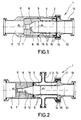
- the ventilation nozzle 1 has a liquid channel 2 which extends over part of it Length is surrounded by a closed annular chamber 3.
- the annular chamber is provided with a gas supply opening 4. 25-30 holes with a diameter of at most one millimeter are formed in the wall of the liquid channel 2 in the area of the annular chamber 3.
- the distance between two of the holes 5 is at least 10 mm and the holes are offset from one another in the circumferential direction.
- the gas supply opening 4 has a cross-sectional area of at least 1 1/2 times the size of the total gas inlet areas formed by the bores.
- the liquid channel 2 is connected to the mixing chamber 7 via a conically tapering wall 6.
- the mixing chamber has an inner diameter d2 which is smaller than the inner diameter d2 of the liquid channel.
- the tapered wall forms an angle ⁇ with the axis of the outer wall of the liquid channel 2, which is at most 22 °.
- the mixing chamber 7 has a length which corresponds to at least 1 1/2 times the inner diameter d2 of the mixing chamber 7.
- the liquid encased in the gas network is mixed in a laminar manner as it passes through the tapered wall 6 and the mixing chamber 7, the occurrence of turbulence being avoided.
- the mixing chamber 7 ends in an expansion space 9, in which the Liquid gas mixture is expanded over a pressure drop. The expansion of the incoming liquid gas mixture creates a particularly uniform and effective bubble formation in the liquid.
- the ventilation nozzle 1 is divided into an inner sleeve 10 and an outer sleeve 11.
- the inner sleeve 10 is inserted into the outer sleeve 11 such that the inner sleeve 10 is seated on a stop surface 12 of the outer sleeve 11.
- the annular chamber 3 is formed by the inner sleeve 10 and the outer sleeve 11.
- the liquid channel 2, the conically tapering wall 6 and the mixing chamber 7 are parts of the inner sleeve 10.
- Part of the expansion space 9 is part of the outer sleeve 11.
- the inner sleeve 10 is completely contained in the outer sleeve 11.
- a neck piece 13 is screwed to the outer sleeve 11 with a closure 14, whereby the inner sleeve 10 is pressed onto the stop surface 12 of the outer sleeve 11.
- the closure 14 is sealed with an O-ring.
- grooves 16 for receiving O-rings 15 are formed on both sides of the annular chamber 3 in the inner wall of the outer sleeve 11. As a result, the annular chamber 3 is sealed so that an excess pressure can be effectively maintained therein.
- the liquid duct 2 and the connecting piece 13 are parts of the inner sleeve 10.
- the tapered wall 6, the mixing chamber 7 and part of the expansion space 9 are parts of the outer sleeve 11.
- the inner sleeve 10 projects beyond the outer sleeve 11 and forms a collar 16 together with the outer sleeve.
- a union nut 18 is screwed over the collar 16, the inner sleeve 10 is pressed onto the stop surface 12 of the outer sleeve 11.
- the grooves 16 for receiving O-rings 15, with which the ring chamber 3 is sealed, are arranged between the stop surface 12 and the end of the inner sleeve 10 resting there and in the collar 17 between the inner sleeve 10 and the outer sleeve 11.
- the mode of operation of the aeration nozzle is to be described below using a method for aerating wort.
- the wort is fed to the liquid channel 2 via the connecting piece 13 with an overpressure between 3 and 5 bar and a volume flow of 0.5-200 m3 / h. Air with an overpressure of 3.5 - 8 bar and a volume flow of 2 - 100 standard liters / min. the annular chamber 3 supplied. Since the gas supply opening 4 has a cross-sectional area of at least 1 1/2 times the total area formed by the bores 5, the gas is distributed evenly in the annular chamber 3 with an overpressure. The gas flows evenly through all bores 5 into the liquid channel 2 where it envelops the liquid in a network. Liquid and gas flow together through the tapered wall 6 into the mixing chamber 7.
- the liquid gas flow is reduced from the diameter d1 of the liquid channel 2 to the diameter d2 of the mixing chamber 7.
- the reduction of the flow cross-section takes place sufficiently continuously, namely with the angle of inclination ⁇ of at most 22 °, which the axis 8 of the outer wall of the liquid channel 2 forms with the tapered wall 6.
- air and wort are mixed in a laminar manner so that turbulence is avoided will.
- the aerated wort runs through a length of the mixing chamber 7 which corresponds to at least 1 1/2 times the diameter d2 of the mixing chamber 7.
- the aerated wort is expanded into the expansion space 9 via a pressure gradient, an effective, extremely evenly distributed bubble formation being generated in the wort. This influences the flotation in such a way that extremely uniform foam blanket formation is achieved.
Claims (25)
- Buse pour l'aération de liquides contenant des substances organiques, comprenant un canal de liquide (2) en forme de cylindre creux, avec au moins une ouverture d'entrée de gaz (5) pour l'addition d'un gaz à un liquide parcourant le canal de liquide (2), et une chambre de mélange (7) parcourue par le mélange de liquide et de gaz qui est détendu après le passage par la chambre de mélange, par l'intermédiaire d'une différence de pression, dans une chambre de détente (9), caractérisée en ce que le canal de liquide (2) est entouré sur une partie de sa longueur par une chambre annulaire (3) fermée munie d'une ouverture d'amenée de gaz (4), que la paroi du canal de liquide (2) comporte dans la région de la chambre annulaire (3) une multiplicité d'ouvertures d'entrée de gaz (5), l'ouverture d'amenée de gaz (4) présentant une section transversale qui est au moins égale à 1,5 fois la surface d'entrée de gaz totale formée par les ouvertures d'entrée de gaz (5), que la chambre de mélange (7) présence la forme d'un cylindre creux et que le canal de liquide (2) a un diamètre intérieur d1 supérieur au diamètre intérieur d2 de la chambre de mélange (7), que le canal de liquide (2) se raccorde à la chambre de mélange (7) par une paroi conique (6), et que la chambre de mélange (7) présente une longueur qui correspond au moins à 1,5 fois le diamètre intérieur d2 de ladite chambre de mélange (7).
- Buse d'aération selon la revendication 1, caractérisée en ce que les ouvertures d'entrée de gaz (5) sont constituées par des alésages dont le diamètre est de 1 mm au maximum.
- Buse d'aération selon l'une des revendications 1 ou 2, caractérisée en ce que dans la paroi du canal de liquide (2), dans la région de la chambre annulaire, sont ménagées 25 à 30 ouvertures d'entrée de gaz (5).
- Buse d'aération selon l'une des revendications 1 à 3, caractérisée en ce que la distance entre respectivement deux ouvertures d'entrée de gaz (5) est d'au moins 10 mm.
- Buse d'aération selon l'une des revendications 1 à 4, caractérisée en ce que les ouvertures d'entrée de gaz (5) sont disposées le long de la paroi du canal de liquide (2) et décalées les unes par rapport aux autres dans le sens circonférentiel.
- Buse d'aération selon l'une des revendications 1 à 5, caractérisée en ce que la paroi conique (6) forme avec l'axe (8) de la paroi du canal de liquide (2) un angle d'au maximum 22°.
- Buse d'aération selon l'une des revendications 1 à 6, caractérisée en ce que le canal de liquide (2) fait partie d'une douille intérieure (10), qu'une partie de la chambre de détente (9) et l'ouverture d'amenée de gaz (4) font partie d'une douille extérieure (11) et que la chambre annulaire (3) est formée par l'engagement de la douille intérieure (10) dans la douille extérieure (11), la douille intérieure (10) formant une paroi intérieure, et la douille extérieure (11), une paroi extérieure de la chambre annulaire (3).
- Buse d'aération selon la revendication 7, caractérisée en ce que la paroi conique (6) et la chambre de mélange (7) sont conformées dans la douille extérieure (11).
- Buse d'aération selon la revendication 7, caractérisée en ce que la paroi conique (6) et la chambre de mélange (7) sont conformées dans la douille intérieure (10).
- Buse d'aération selon l'une des revendications 7 à 9, caractérisée en ce que la douille intérieure (10) comprend au moins une section de paroi dont le diamètre extérieur est adapté au diamètre intérieur de la douille extérieure (11).
- Buse d'aération selon la revendication 10, caractérisée en ce que la chambre annulaire (3) est étanche des deux côtés.
- Buse d'aération selon la revendication 11, caractérisée en ce que pour assurer l'étanchéité de la chambre annulaire (3), des rainures (16) orientées radialement dans le sens circonférentiel et destinées à recevoir à chaque fois un joint d'étanchéité (15) sont ménagées dans la paroi intérieure de la douille extérieure (11) ou dans la paroi extérieure de la douille intérieure (10).
- Buse d'aération selon l'une des revendications 7 à 12, caractérisée en ce que la douille extérieure (11) comprend une surface d'arrêt (12) pour une extrémité de la douille intérieure (10) lors de l'engagement de ladite douille intérieure (10) dans ladite douille extérieure (11).
- Buse d'aération selon la revendication 13, caractérisée en ce qu'un système d'étanchéité (15, 16) est prévu entre la douille intérieure (10) et la surface d'arrêt (12) de la douille extérieure (11).
- Buse d'aération selon l'une des revendications 13 ou 14, caractérisée en ce que la douille intérieure (10) se loge entièrement dans la douille extérieure (11) et qu'elle est pressée par un obturateur (14) contre la surface d'arrêt (12).
- Buse d'aération selon la revendication 15, caractérisée en ce que l'obturateur (14) peut être vissé sur la douille extérieure (11).
- Buse d'aération selon l'une des revendications 15 ou 16, caractérisée en ce que l'obturateur (14) est étanche.
- Buse d'aération selon la revendication 17, caractérisée en ce que l'obturateur (14) fait partie d'une tubulure de raccordement (13).
- Buse d'aération selon la revendication 18, caractèrisée en ce que la tubulure de raccordement (13) fait partie de la douille intérieure (10) , que la douille intérieure (10) dépasse de la douille extérieure (11) et forme conjointement avec ladite douille extérieure (11) un collet (17) sur lequel est vissé un écrou-raccord (18), avec application de la douille intérieure (10) contre la surface d'arrêt (12) de la douille extérieure (11).
- Buse d'aération selon la revendication 19, caractérisée en ce qu'un système d'étanchéité (15, 16) est prévu dans le collet (17), entre la douille intérieure (10) et la douille extérieure (11).
- Buse d'aération selon l'une des revendications 1 à 20, caractérisée en ce qu'une tubulure d'amenée de gaz est conformée sur l'ouverture d'amenée de gaz (4) de la chambre annulaire (3).
- Buse d'aération selon l'une des revendications 11 à 13, caractérisée en ce que les deux extrémités de la buse d'aération (1) et la tubulure d'amenée de gaz sont munies de raccords standardisés.
- Buse d'aération selon la revendication 22, caractérisée en ce que les raccords standardisés présentent des diamètres intérieurs nominaux compris entre DN 20 et DN 200.
- Utilisation de la buse d'aération selon l'une des revendications 1 à 23 pour l'aération de moût.
- Utilisation selon la revendication 24, caractérisée en ce que le moût est amené par le canal de liquide (2) avec une surpression de 3 à 5 bars et un flux volumique de 0,5 à 200 m³/h, et que l'air est ajouté au moût avec une surpression de 3,5 à 8 bars et un flux volumique de 2 à 100 litres à l'état normal/min.
Applications Claiming Priority (3)
| Application Number | Priority Date | Filing Date | Title |
|---|---|---|---|
| DE4029982 | 1990-09-21 | ||
| DE4029982A DE4029982C2 (de) | 1990-09-21 | 1990-09-21 | Vorrichtung zum Begasen einer Flüssigkeit |
| PCT/EP1991/001794 WO1992004972A1 (fr) | 1990-09-21 | 1991-09-20 | Buse d'aeration de liquides contenant des substances organiques |
Publications (2)
| Publication Number | Publication Date |
|---|---|
| EP0550510A1 EP0550510A1 (fr) | 1993-07-14 |
| EP0550510B1 true EP0550510B1 (fr) | 1994-12-21 |
Family
ID=6414725
Family Applications (1)
| Application Number | Title | Priority Date | Filing Date |
|---|---|---|---|
| EP91916556A Expired - Lifetime EP0550510B1 (fr) | 1990-09-21 | 1991-09-20 | Buse d'aeration de liquides contenant des substances organiques |
Country Status (6)
| Country | Link |
|---|---|
| EP (1) | EP0550510B1 (fr) |
| JP (1) | JPH0811174B2 (fr) |
| AT (1) | ATE115889T1 (fr) |
| DE (2) | DE4029982C2 (fr) |
| ES (1) | ES2066472T3 (fr) |
| WO (1) | WO1992004972A1 (fr) |
Cited By (1)
| Publication number | Priority date | Publication date | Assignee | Title |
|---|---|---|---|---|
| WO2021001448A1 (fr) | 2019-07-04 | 2021-01-07 | Fraunhofer-Gesellschaft zur Förderung der angewandten Forschung eingetragener Verein | Silicone à surface modifiée, son utilisation dans des revêtements anti-adhésifs et matériau composite contenant ladite silicone |
Families Citing this family (19)
| Publication number | Priority date | Publication date | Assignee | Title |
|---|---|---|---|---|
| DE9111657U1 (fr) * | 1991-09-18 | 1991-11-14 | Anton Steinecker Entwicklungs-Gmbh & Co., 8050 Freising, De | |
| DE4206715C2 (de) * | 1992-03-04 | 1997-06-26 | Gaston M Wopfner | Verfahren und Vorrichtung zum Einbringen eines Gases in eine Flüssigkeit |
| DE9302862U1 (fr) * | 1993-02-26 | 1993-05-27 | Anton Steinecker Entwicklungs Gmbh & Co, 8050 Freising, De | |
| DE9303761U1 (fr) * | 1993-03-15 | 1993-06-24 | Hoechst Ag, 6230 Frankfurt, De | |
| NL9301658A (nl) * | 1993-09-24 | 1995-04-18 | Heineken Tech Services | Werkwijze en inrichting voor het toevoegen van een gas aan een vloeistof. |
| DE4446000C2 (de) * | 1994-12-22 | 1997-11-20 | Hrch Huppmann Maschf Gmbh | Vorrichtung zum Mischen zweier strömender Fluide, insbesondere zum Belüften von Würze für die Bierherstellung |
| AUPN683795A0 (en) * | 1995-11-27 | 1995-12-21 | Burns Philp Food Holdings Pty Limited | A device for entraining a gas into a liquid |
| US6076810A (en) * | 1997-10-21 | 2000-06-20 | Exxon Research And Engineering Co. | Throat and cone gas injector and gas distribution grid for slurry reactor |
| DE19835434C2 (de) * | 1998-08-05 | 2000-08-17 | Wolfgang Reuschl | Vorrichtung und Verfahren zur sterilen Abtrennung von Feststoffpartikeln aus Suspensionen mittels pneumatischer Flotation in kontinuierlicher Betriebsweise |
| DE20105711U1 (de) | 2000-04-05 | 2002-01-17 | Rummel Manfred | Düse zum Aufschäumen, Versprühen oder Vernebeln |
| EP1254700A1 (fr) * | 2001-05-03 | 2002-11-06 | Sulzer Chemtech AG | Anneau à brides intermédiaire pour une jonction de tuyaux pour l'introduction d'additives dans un écoulement de fluide |
| AT410406B (de) * | 2001-09-17 | 2003-04-25 | Andritz Ag Maschf | Verfahren und vorrichtung zur belüftung einer flüssigkeit mit gas |
| WO2008077287A1 (fr) * | 2006-12-27 | 2008-07-03 | Ningbo Wanhua Polyurethanes Co. Ltd. | Réacteur à injection du type à gicleur à orifice |
| EP2308601A1 (fr) * | 2009-09-29 | 2011-04-13 | Siemens Aktiengesellschaft | Buse de dispersion, machine de flottation en étant équipée et son procédé de fonctionnement |
| EP2476530A1 (fr) * | 2011-01-12 | 2012-07-18 | Sika Technology AG | Pièce auxiliaire et élément de boîtier pour un dispositif de mélange |
| DE102012002345A1 (de) * | 2012-02-08 | 2013-08-08 | Krones Ag | Naßschrotmühle für die Maischeherstellung bei der Biererzeugung |
| DE102013220363A1 (de) * | 2013-10-09 | 2015-04-09 | Siemens Aktiengesellschaft | Flotationsvorrichtung sowie Verfahren zum Betreiben einer Flotationsvorrichtung |
| DE112018006074T5 (de) * | 2017-11-29 | 2020-09-03 | Toshiba Lifestyle Products & Services Corporation | Mikroblasengenerator, Waschmaschine und Haushaltsgerät |
| DE102018108881A1 (de) | 2018-04-13 | 2019-10-17 | Fraunhofer-Gesellschaft zur Förderung der angewandten Forschung eingetragener Verein | Oberflächenmodifiziertes Silikon, dessen Verwendung in Antihaftbeschichtungen sowie dieses enthaltendes Verbundmaterial |
Family Cites Families (14)
| Publication number | Priority date | Publication date | Assignee | Title |
|---|---|---|---|---|
| DE649817C (de) * | 1929-10-11 | 1937-09-04 | Thomas Walter Barber | Vorrichtung zum Mischen von stroemenden Fluessigkeiten oder Gasen oder von Gasen mit Fluessigkeiten |
| DE583849C (de) * | 1930-11-08 | 1933-09-11 | Gustav Schlick | Vorrichtung zum Einfuehren von Gasen in stroemende Fluessigkeiten |
| GB694918A (en) * | 1951-02-23 | 1953-07-29 | F S Gibbs Inc | Diffusion of gases in liquids |
| DE1459453B2 (de) * | 1963-11-20 | 1972-04-20 | Asendorf, Knut Erich, 6380 Bad Horn bürg | Abwasserklaeranlage |
| DE1996056U (de) * | 1968-04-13 | 1968-11-07 | Moll Maschinenfabrik G M B H | Strahlapparat zum mischen zweier fluessigkeiten |
| ZA733022B (en) * | 1972-07-20 | 1974-03-27 | Strenger Associates | Instantaneous carbonator |
| CH581493A5 (en) * | 1974-06-24 | 1976-11-15 | Escher Wyss Ag | Static mixer for in line mixing - having sudden expansion with secondary fluid injection just prior to it |
| DE2601431A1 (de) * | 1976-01-16 | 1977-07-21 | Wiegand Karlsruhe Gmbh | Direkt-dampf-injektionsgeraet |
| DE2627880C2 (de) * | 1976-06-22 | 1982-11-11 | Jogindar Mohan Dr.-Ing. 7505 Ettlingen Chawla | Verfahren für die Zerstäubung von Flüssigkeiten oder für die Zerteilung von Gasen in kleine Blasen |
| DE2907694C2 (de) * | 1979-02-27 | 1984-11-22 | Mannesmann AG, 4000 Düsseldorf | Mischvorrichtung für strömende flüssige, gas- oder dampfförmige Medien |
| BR8403815A (pt) * | 1983-08-23 | 1985-07-09 | Technica Entwicklung | Processo e aparelho para impregnacao de um liquido com um gas e,mais especificamente,para impregnacao de agua de irrigacao com co2 para plantacoes comerciais horticolas,jardinagem de lazer ou similares,e conjunto para obtencao do processo |
| BR8503919A (pt) * | 1985-08-16 | 1987-03-24 | Liquid Carbonic Ind Sa | Ejetor para o processo co2 na neutralizacao de aguas alcalinas |
| DE3804699A1 (de) * | 1988-02-15 | 1989-08-17 | Technica Entwicklung | Verfahren und vorrichtung zur geschmacksverbesserung von stillen getraenken |
| EP0445169A1 (fr) | 1988-11-22 | 1991-09-11 | Dunne Miller Weston Limited | Dispositif permettant de melanger un gaz et un liquide |
-
1990
- 1990-09-21 DE DE4029982A patent/DE4029982C2/de not_active Expired - Fee Related
-
1991
- 1991-09-20 EP EP91916556A patent/EP0550510B1/fr not_active Expired - Lifetime
- 1991-09-20 JP JP3515232A patent/JPH0811174B2/ja not_active Expired - Lifetime
- 1991-09-20 AT AT91916556T patent/ATE115889T1/de not_active IP Right Cessation
- 1991-09-20 WO PCT/EP1991/001794 patent/WO1992004972A1/fr active IP Right Grant
- 1991-09-20 ES ES91916556T patent/ES2066472T3/es not_active Expired - Lifetime
- 1991-09-20 DE DE59104001T patent/DE59104001D1/de not_active Expired - Lifetime
Cited By (1)
| Publication number | Priority date | Publication date | Assignee | Title |
|---|---|---|---|---|
| WO2021001448A1 (fr) | 2019-07-04 | 2021-01-07 | Fraunhofer-Gesellschaft zur Förderung der angewandten Forschung eingetragener Verein | Silicone à surface modifiée, son utilisation dans des revêtements anti-adhésifs et matériau composite contenant ladite silicone |
Also Published As
| Publication number | Publication date |
|---|---|
| DE59104001D1 (de) | 1995-02-02 |
| EP0550510A1 (fr) | 1993-07-14 |
| WO1992004972A1 (fr) | 1992-04-02 |
| DE4029982C2 (de) | 2000-08-10 |
| JPH06502342A (ja) | 1994-03-17 |
| DE4029982A1 (de) | 1992-03-26 |
| ES2066472T3 (es) | 1995-03-01 |
| ATE115889T1 (de) | 1995-01-15 |
| JPH0811174B2 (ja) | 1996-02-07 |
Similar Documents
| Publication | Publication Date | Title |
|---|---|---|
| EP0550510B1 (fr) | Buse d'aeration de liquides contenant des substances organiques | |
| DE2634496C2 (de) | Injektor zur Begasung einer Flüssigkeit | |
| EP2178624B1 (fr) | Dispositif pour enrichir un courant de liquide avec un gaz | |
| EP1243343A1 (fr) | Buse de vaporisation à deux fluides | |
| DE4016727C2 (fr) | ||
| EP0614693B1 (fr) | Gicleur d'aération pour aérer des liquides contenant des substances organiques | |
| EP0533104B1 (fr) | Gicleur d'aération pour liquide | |
| DE3640315C2 (fr) | ||
| EP1356868A1 (fr) | Buse binaire avec un insert changeables | |
| EP1293255B1 (fr) | Procédé et dispositif de séparation de saletés de suspensions par flottation | |
| WO2009086822A2 (fr) | Procédé et dispositif correspondant d'introduction sans pression ou essentiellement sans pression de mousse dans un flux de matériau sous pression | |
| DE4005691A1 (de) | Vorrichtung zum schneiden und reinigen von gegenstaenden mittels eines wasser-abrasivmittel-gemisches bei hohem umgebungsdruck | |
| EP2247373B1 (fr) | Procédé et utilisation d'un dispositif d'introduction d'air dans de l'eau | |
| DE2459710B2 (de) | Selbstansaugendes Belüften und Begasen von Flüssigkeiten | |
| EP0264689B1 (fr) | Appareil producteur de mousse | |
| DE2657791A1 (de) | Duese, insbesondere mischduese | |
| DE3220880C2 (de) | Verfahren zum Mischen von Beton-Trockengemisch und Wasser beim Beton-Trockenspritzen und Mischrohr zum Beton-Trockenspritzen | |
| DE3611589A1 (de) | Statische mischvorrichtung | |
| DE2441335A1 (de) | Verfahren und vorrichtung zum einfuehren von luft oder gas in eine in bewegung befindliche fluessigkeit | |
| DE2410574A1 (de) | Druckstrahler zum begasen von fluessigkeiten, insbesondere von fermentationsfluessigkeiten und abwasser | |
| DE4446000C2 (de) | Vorrichtung zum Mischen zweier strömender Fluide, insbesondere zum Belüften von Würze für die Bierherstellung | |
| CH431465A (de) | Mischdüse zum Einbringen und Feinverteilen eines Gases oder einer Flüssigkeit in einen Flüssigkeitsstrom | |
| EP0262585B1 (fr) | Dispositif à mélanger avec gicleur rotatif | |
| DE1551647C3 (fr) | ||
| WO1992017270A1 (fr) | Melangeur de fluides |
Legal Events
| Date | Code | Title | Description |
|---|---|---|---|
| PUAI | Public reference made under article 153(3) epc to a published international application that has entered the european phase |
Free format text: ORIGINAL CODE: 0009012 |
|
| 17P | Request for examination filed |
Effective date: 19930315 |
|
| AK | Designated contracting states |
Kind code of ref document: A1 Designated state(s): AT BE CH DE ES FR GB IT LI LU NL |
|
| 17Q | First examination report despatched |
Effective date: 19940215 |
|
| GRAA | (expected) grant |
Free format text: ORIGINAL CODE: 0009210 |
|
| AK | Designated contracting states |
Kind code of ref document: B1 Designated state(s): AT BE CH DE ES FR GB IT LI LU NL |
|
| REF | Corresponds to: |
Ref document number: 115889 Country of ref document: AT Date of ref document: 19950115 Kind code of ref document: T |
|
| ET | Fr: translation filed | ||
| REF | Corresponds to: |
Ref document number: 59104001 Country of ref document: DE Date of ref document: 19950202 |
|
| GBT | Gb: translation of ep patent filed (gb section 77(6)(a)/1977) |
Effective date: 19950112 |
|
| ITF | It: translation for a ep patent filed |
Owner name: JACOBACCI & PERANI S.P.A. |
|
| REG | Reference to a national code |
Ref country code: ES Ref legal event code: FG2A Ref document number: 2066472 Country of ref document: ES Kind code of ref document: T3 |
|
| PLBE | No opposition filed within time limit |
Free format text: ORIGINAL CODE: 0009261 |
|
| STAA | Information on the status of an ep patent application or granted ep patent |
Free format text: STATUS: NO OPPOSITION FILED WITHIN TIME LIMIT |
|
| 26N | No opposition filed | ||
| REG | Reference to a national code |
Ref country code: GB Ref legal event code: IF02 |
|
| PGFP | Annual fee paid to national office [announced via postgrant information from national office to epo] |
Ref country code: GB Payment date: 20020829 Year of fee payment: 12 |
|
| PGFP | Annual fee paid to national office [announced via postgrant information from national office to epo] |
Ref country code: ES Payment date: 20020913 Year of fee payment: 12 |
|
| PGFP | Annual fee paid to national office [announced via postgrant information from national office to epo] |
Ref country code: FR Payment date: 20020920 Year of fee payment: 12 |
|
| PGFP | Annual fee paid to national office [announced via postgrant information from national office to epo] |
Ref country code: LU Payment date: 20020925 Year of fee payment: 12 |
|
| PG25 | Lapsed in a contracting state [announced via postgrant information from national office to epo] |
Ref country code: LU Free format text: LAPSE BECAUSE OF NON-PAYMENT OF DUE FEES Effective date: 20030920 Ref country code: GB Free format text: LAPSE BECAUSE OF NON-PAYMENT OF DUE FEES Effective date: 20030920 |
|
| PG25 | Lapsed in a contracting state [announced via postgrant information from national office to epo] |
Ref country code: ES Free format text: LAPSE BECAUSE OF NON-PAYMENT OF DUE FEES Effective date: 20030922 |
|
| PGFP | Annual fee paid to national office [announced via postgrant information from national office to epo] |
Ref country code: CH Payment date: 20030925 Year of fee payment: 13 |
|
| GBPC | Gb: european patent ceased through non-payment of renewal fee |
Effective date: 20030920 |
|
| PG25 | Lapsed in a contracting state [announced via postgrant information from national office to epo] |
Ref country code: FR Free format text: LAPSE BECAUSE OF NON-PAYMENT OF DUE FEES Effective date: 20040528 |
|
| REG | Reference to a national code |
Ref country code: FR Ref legal event code: ST |
|
| PG25 | Lapsed in a contracting state [announced via postgrant information from national office to epo] |
Ref country code: CH Free format text: LAPSE BECAUSE OF NON-PAYMENT OF DUE FEES Effective date: 20040930 Ref country code: LI Free format text: LAPSE BECAUSE OF NON-PAYMENT OF DUE FEES Effective date: 20040930 |
|
| REG | Reference to a national code |
Ref country code: ES Ref legal event code: FD2A Effective date: 20030922 |
|
| REG | Reference to a national code |
Ref country code: CH Ref legal event code: PL |
|
| PG25 | Lapsed in a contracting state [announced via postgrant information from national office to epo] |
Ref country code: IT Free format text: LAPSE BECAUSE OF NON-PAYMENT OF DUE FEES;WARNING: LAPSES OF ITALIAN PATENTS WITH EFFECTIVE DATE BEFORE 2007 MAY HAVE OCCURRED AT ANY TIME BEFORE 2007. THE CORRECT EFFECTIVE DATE MAY BE DIFFERENT FROM THE ONE RECORDED. Effective date: 20050920 |
|
| PGFP | Annual fee paid to national office [announced via postgrant information from national office to epo] |
Ref country code: AT Payment date: 20050926 Year of fee payment: 15 |
|
| PG25 | Lapsed in a contracting state [announced via postgrant information from national office to epo] |
Ref country code: AT Free format text: LAPSE BECAUSE OF NON-PAYMENT OF DUE FEES Effective date: 20060920 |
|
| PGFP | Annual fee paid to national office [announced via postgrant information from national office to epo] |
Ref country code: NL Payment date: 20060925 Year of fee payment: 16 |
|
| PG25 | Lapsed in a contracting state [announced via postgrant information from national office to epo] |
Ref country code: NL Free format text: LAPSE BECAUSE OF NON-PAYMENT OF DUE FEES Effective date: 20080401 |
|
| NLV4 | Nl: lapsed or anulled due to non-payment of the annual fee |
Effective date: 20080401 |
|
| PGFP | Annual fee paid to national office [announced via postgrant information from national office to epo] |
Ref country code: DE Payment date: 20090917 Year of fee payment: 19 |
|
| PGFP | Annual fee paid to national office [announced via postgrant information from national office to epo] |
Ref country code: BE Payment date: 20090917 Year of fee payment: 19 |
|
| BERE | Be: lapsed |
Owner name: ANTON *STEINECKER ENTWICKLUNGS G.M.B.H. & CO. Effective date: 20100930 |
|
| REG | Reference to a national code |
Ref country code: DE Ref legal event code: R119 Ref document number: 59104001 Country of ref document: DE Effective date: 20110401 |
|
| PG25 | Lapsed in a contracting state [announced via postgrant information from national office to epo] |
Ref country code: DE Free format text: LAPSE BECAUSE OF NON-PAYMENT OF DUE FEES Effective date: 20110401 Ref country code: BE Free format text: LAPSE BECAUSE OF NON-PAYMENT OF DUE FEES Effective date: 20100930 |