EP0550323B1 - Dispositif de connexion pour composants d'un réseau de distribution de fluides, réseau et composants faisant application - Google Patents
Dispositif de connexion pour composants d'un réseau de distribution de fluides, réseau et composants faisant application Download PDFInfo
- Publication number
- EP0550323B1 EP0550323B1 EP92403499A EP92403499A EP0550323B1 EP 0550323 B1 EP0550323 B1 EP 0550323B1 EP 92403499 A EP92403499 A EP 92403499A EP 92403499 A EP92403499 A EP 92403499A EP 0550323 B1 EP0550323 B1 EP 0550323B1
- Authority
- EP
- European Patent Office
- Prior art keywords
- distribution line
- line according
- sleeve
- teeth
- connection
- Prior art date
- Legal status (The legal status is an assumption and is not a legal conclusion. Google has not performed a legal analysis and makes no representation as to the accuracy of the status listed.)
- Expired - Lifetime
Links
Images


Classifications
-
- F—MECHANICAL ENGINEERING; LIGHTING; HEATING; WEAPONS; BLASTING
- F16—ENGINEERING ELEMENTS AND UNITS; GENERAL MEASURES FOR PRODUCING AND MAINTAINING EFFECTIVE FUNCTIONING OF MACHINES OR INSTALLATIONS; THERMAL INSULATION IN GENERAL
- F16L—PIPES; JOINTS OR FITTINGS FOR PIPES; SUPPORTS FOR PIPES, CABLES OR PROTECTIVE TUBING; MEANS FOR THERMAL INSULATION IN GENERAL
- F16L37/00—Couplings of the quick-acting type
- F16L37/08—Couplings of the quick-acting type in which the connection between abutting or axially overlapping ends is maintained by locking members
- F16L37/084—Couplings of the quick-acting type in which the connection between abutting or axially overlapping ends is maintained by locking members combined with automatic locking
- F16L37/091—Couplings of the quick-acting type in which the connection between abutting or axially overlapping ends is maintained by locking members combined with automatic locking by means of a ring provided with teeth or fingers
-
- F—MECHANICAL ENGINEERING; LIGHTING; HEATING; WEAPONS; BLASTING
- F16—ENGINEERING ELEMENTS AND UNITS; GENERAL MEASURES FOR PRODUCING AND MAINTAINING EFFECTIVE FUNCTIONING OF MACHINES OR INSTALLATIONS; THERMAL INSULATION IN GENERAL
- F16L—PIPES; JOINTS OR FITTINGS FOR PIPES; SUPPORTS FOR PIPES, CABLES OR PROTECTIVE TUBING; MEANS FOR THERMAL INSULATION IN GENERAL
- F16L19/00—Joints in which sealing surfaces are pressed together by means of a member, e.g. a swivel nut, screwed on or into one of the joint parts
- F16L19/08—Joints in which sealing surfaces are pressed together by means of a member, e.g. a swivel nut, screwed on or into one of the joint parts with metal rings which bite into the wall of the pipe
- F16L19/10—Joints in which sealing surfaces are pressed together by means of a member, e.g. a swivel nut, screwed on or into one of the joint parts with metal rings which bite into the wall of the pipe the profile of the ring being altered
- F16L19/12—Joints in which sealing surfaces are pressed together by means of a member, e.g. a swivel nut, screwed on or into one of the joint parts with metal rings which bite into the wall of the pipe the profile of the ring being altered with additional sealing means
Definitions
- the present invention relates to a device for connecting between a pipe section and a functional or connection component of a pressurized fluid installation, allowing the creation of a fluid distribution network in a simple, rapid, rational and scalable or configurable according to the changing needs of the user.
- the present invention intends to remedy the drawbacks of current installations and their installation technique by mainly proposing connection means which allow extremely rapid assembly of a new installation with the possibility of easily modifying its configuration, the nature or the location of the functional elements that constitute it.
- connection means specific to the invention makes it possible to divide the pipe or pipes which make up the installation or the network into modular elements or sections which it is easy to replace or modify, these sections being provided in a series of predetermined lengths and having no specific end means for their connection to the installation.
- the connection means are concentrated in a specific element interposed between the end of a section and a functional member, this functional member being able to be reduced to a union or a plug.
- the subject of the invention is a pressure-free fluid distribution line comprising at least one section of pipe and at least one functional element or of connection with a nozzle, the connection of the nozzle to the segment being ensured by a device which comprises a tubular sleeve divided into two axially successive parts, the first part being fitted internally with the components of an instant connection connector for the end of the pipe section, the second part comprising means for sealing and removable covering connection end piece, the end face of which constitutes, when the end piece is capped with the sleeve, an axial stop of the end of the section engaged in the first part of the sleeve.
- This sleeve grouping the connection means has many advantages. The first is that it can be pre-mounted on the connection ends of an organ.
- Each member thus equipped is therefore instantaneous connection for the pipe sections which surround it.
- the second advantage is such that by "disheveling" each end piece, it is possible to separate an organ from the sections which surround it and remove this organ without moving the sections which each carry a tubular sleeve awaiting another organ to "recoiff" insofar as it is interchangeable with the deposited member.
- the means for covering the end piece include a tapping of the second part of the sleeve to cooperate with an external thread of the end piece.
- the so-called instant connection fittings have been known for many years. They consist essentially, in their simplest embodiment, of a tubular element which is attached by screwing into the threaded orifice of a member such as a distributor, a jack, a valve, etc. and which comprises, inside, means for sealingly accommodating the tube and for, once engaged, retaining it there against an effort tending to extract it.
- a member such as a distributor, a jack, a valve, etc.
- These means which grip the end of the tube inside this tubular element can be of two types. Mention will be made of the slightly conical washer, provided with teeth on its internal periphery which delimits an internal diameter of passage smaller than the external diameter of the tube so that the teeth come to bite on this tube.
- the second known device consists of a kind of tubular bushing, one end of which is divided into longitudinal tongues fitted at their end with a tooth turned radially inwards, these tongues cooperating with a kind of circumferential stop located inside the 'tubular tip which, during a force tending to extract the tube out of this tubular element, radially forces the teeth to bite into the tube.
- the free passage between the teeth, the sleeve being at rest is also less than the outside diameter of the tube.
- connection devices are generally non-removable. It appeared however the need to make them removable, and this as quickly as possible, and for that we created more complex devices comprising tubular pushers interposed between the teeth and the tube, allowing, by moving them relative to the teeth, along the tube, spread these teeth and release the tube which can then be extracted.
- the action on these pushers is generally in the opposite direction to the direction of extraction of the tube, so that manipulation of this type of fittings is not always very easy, especially when these are small.
- an instantaneous connection the components of which include teeth retaining the end of the section engaged in the first part. which are integral with a deformable support between a first "rest” state in which the retaining teeth are disposed completely outside of a circumference equal to that outside of the tube to be retained and a second state, "in use” wherein the retaining teeth extend at least partially inside this circumference, while means for deforming the support are provided to make it pass from its first to its second state and to maintain it in this second state.
- the device for retaining a tube which can be armed and disarmed, either before or after the introduction of the tube into the connection piece.
- the device can be armed before the introduction of the tube, the latter then playing the role of a conventional connection device, or introduce the tube then arm the device so that the teeth penetrate the external surface of the tube after it has been inserted, the disconnection being effected in both cases by disarming, that is to say by de-stressing the support member of the retaining teeth so that these, under the effect of elastic deformation towards its resting state of the tooth support, is placed outside the tube, thereby releasing the latter.
- the support is constituted by a washer fitted with internal teeth contained in a substantially frustoconical surface whose large base is attached to a continuous external crown, which is contained in a surface different from a radial plane, the deformation means of the support comprising two radial gripping surfaces of at least the outer ring of the washer, movable relative to each other in the axial direction inside the end piece, which are respectively carried by a radial shoulder of the first part of the tubular sleeve and via the radial face of a spacer ring, the other face of which bears on the end face of the connection end piece.
- the support is in the form of a clamp whose arms are oriented substantially axially, the free ends of these arms forming the retaining teeth of the tube, the means of deformation of the clamp then comprising cooperating cam surfaces with the outer part of the teeth to make them pass from the first to the second state and release them so that they pass because of their own elasticity, from the second state where the teeth are active to the first state where they are inactive.
- the cam surfaces can be controlled manually, either by rotation of a ring which allows the teeth to be inserted into the tube, or by an axial thrust of a ring with a conical surface which also leads to a depression of these teeth.
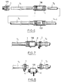
- connection device intended to ensure the connection between a section of pipe T and a connection piece E belonging to an apparatus or to a functional member installed in line on the pipe .
- This connection device is essentially constituted by a tubular sleeve 1 divided into two axially successive parts 2 and 3, the part 2 being fitted internally with components to produce an instant connection, the part 3 being intended to cover, in a removable manner, the end piece E of the device or of the member to be connected to the pipe section T.
- these instant connection means consist of a metal washer 4, of frustoconical shape and having teeth 5 on the side of its inner circumference to bite the outer surface of the tube section T and prevent its removal when that -this is introduced into zone 2 of the sleeve 1.
- the washer 4 is elastically deformable between a position shown in which the inside diameter of the washer 4 defined by the ends of the teeth 5, is greater than the outside diameter of the section T and a position in which the washer 4 is compressed between two radial surfaces 6, 7, the effect of which is to modify the angle of the truncated cone and thus to place the ends of the teeth 5 on a circumference smaller than the circumference of the section T.
- the surface 6 belongs to a ring 8 which rests on a shoulder 9 inside the part 2 of the sleeve 1 while the surface 7 belongs to a ring 10 which is axially movable inside this sleeve, the compression of the washer 4 being ensured by the action of the end piece E on the ring 10 when this end piece E is capped by the part 3 of the tubular sleeve 1.
- the end piece E is here externally threaded and to cap this end piece E in a removable manner, the sleeve 1 has in its zone 3 an internal thread 11. It is therefore by screwing the sleeve 1 on the end piece E that is caused the crushing of the washer 4 between the two rings 8 and 10, thus arming the instant connection elements.
- the axial zone 2 of the sleeve 1 has, beyond the shoulder 9, a lip seal 12 which seals between the sleeve 1 and the section T.
- the ring 10 has a front seal 13 which seals between the sleeve 1 and the end piece E. The connection between the end piece E and the pipe T is therefore sealed.
- the front face 14 of the end piece E constitutes a stop for the insertion into the sleeve 1 of the end of the section T when the end piece E is screwed into the zone 3 of the sleeve 1.
- each member or device to be connected to a section of pipe T can be pre-equipped with a sleeve 1 which is screwed onto the end piece E so that the instant connection elements that this sleeve comprises are reinforced as illustrated in FIG. 2
- the connection of an apparatus thus provided to a section T of pipe is carried out simply by fitting the section T into the sleeve 1, this fitting being stopped by the contact between the end face 15 of the section T and the front face 14. of the end piece E.
- the washer 4 (see FIG. 3) at instead of being tapered , can be formed in a toric surface portion. In the free state, its inside diameter d is greater than that outside of the tube section T.
- FIG 4 shows two alternative embodiments of a connection device according to the invention, one concerning the means associated with the second axial part of the sleeve 1 for sealingly and demountably fitting the connection end piece E, l other concerning the instant connection means housed in the first axial part of the sleeve 1.
- the screw coupling between the end piece E and the sleeve 1 is replaced by a coupling collar 16, for example in two articulated half-parts, the closure of which straddles the sleeve 1 and the end piece E allows, thanks to the cooperation of conical surfaces 17, 18 provided respectively on the collar and on the outside of the end piece, to firmly hold the end piece E inside a cylindrical surface 19 of the second zone axial 3 of the sleeve 1, provided with a seal 20, against a shoulder 21 axially limiting this bearing 19.
- the instant connection means use a clamp 22 whose axial arms 23 are elastic and terminated by teeth 24.
- the tip of the teeth 24 is, at rest, situated on a circumference of diameter larger than the outside diameter of the tube T.
- These teeth can be forced to penetrate into the tube T by means of a ring 25 which has cam surfaces 26 which form, when the the ring 25 is turned in the positive direction S in FIG.
- the control of the ring 25 can be effected by means of an external annular control ring 27 which cooperates with at least one extension 28 of the ring 25 passing through the tubular wall sleeve 1.
- FIG. 6 in a partial view, illustrates the constitution of a compressed fluid distribution network according to the invention.
- a functional element 125 is constituted by a straight tap, externally threaded.
- the end piece E for connecting this functional element is covered by a sleeve 1 according to the invention which comprises on the one hand a thread for screwing onto this end piece and on the other hand the instant connection means for receiving one end of the section T1 of pipeline.
- the connection of the section T1 with the successive section T2 is ensured by means of a double union 126 which comprises at each of its ends connection ends on which the sleeves are pre-mounted 1.
- the network comprises, between a section Tn and a section Tn + 1, a functional element 127, for example a tap or a manual valve, connected to these sections by means of the connection device of the invention.
- FIGS. 7 and 8 illustrate how, for example, it is easy to deposit a double union such as that 126 of FIG. 6. It suffices in fact to unscrew each of the sleeve 1 of the ends E of this double union and to slide these sleeves along the sections T1 and T2 to completely release, as shown in FIG. 8, the functional element 126. It is then possible to replace this double union by any functional element which will include, like the double union, in the same place , two end caps E on which the sleeves can be screwed on again. This screwing will at the same time cause, if these sleeves are of the type of embodiment illustrated in FIG. 1, the arming of the instant connection means of the sections T1 and T2.
- Figure 9 is a longitudinal sectional view of a particular double union which has between the two ends E externally threaded, a drain port 128 located at the low point of a lower surface 129 of the double union forming double slope.
- This orifice can be closed by a plug 130 or by any closing device with manual or automatic control, allowing the draining of the pipe, that is to say the draining of the condensation water which it may contain.
- the internal diameter of this component is of course equal to the internal diameter of the pipe sections which it connects to form a stop for mounting and so as not to create a pressure drop in the pipe.
- Figure 10 illustrates in a longitudinal sectional view another functional member capable of being used in a network constructed in accordance with the invention. It is a connection T comprising between two end piece E a third end piece 131 which can have an external thread for its connection either to the device having a corresponding tapping and in this case it will be advantageous. that the external thread is standardized, that is to say determined by the nominal passage diameter of the orifice 132 which it surrounds, either to receive the threaded zone 3 of a sleeve 1 belonging to the connection device conforming to the invention. It will be noted that to avoid a descent of condensation water present in the horizontal sections of a distribution network in the vertical bypass which can be installed on these horizontal sections thanks to the functional T-shaped element of FIG.
- the orifice 132 can, in a variant, be delimited in a threaded insert with a standardized diameter allowing any straight stitching to be implanted.
- one of the advantageous characteristics of the invention resides in the fact that the end faces 114 of the opposite end pieces E of each functional member placed in a network, are spaced from each other by a distance Unique D for all the functional components whether these are union fittings, Tees, valves and taps, or any other device.
- FIG. 11 illustrates the connection of a sleeve 1 according to the invention with a functional element which is reduced to a plug 135, that is to say a radial wall equipped with a cylindrical rim forming a threaded end piece E.
- the radial wall may include means not shown for its actuation by screwing or unscrewing inside the sleeve 1.
- the functional elements according to the invention are not limited to those illustrated above. They also include, for example, elements which have a connecting end piece E and at the other end a thread or a standard thread to allow the connection of a conventional component.
- the sleeve 1 in its embodiment according to Figure 1, has a grooved outer surface which allows its manual operation.
- connection device of the invention by the very fact that it is movable along the length of tube having been dissociated from the end piece of the device or from the member arranged in line between two sections, allows you to quickly modify the configuration of an existing network. It is in particular possible to design a network from a section of pipeline of determined lengths which constitutes the minimum pitch of the network, the location of each connection constituting the potential starting location for a diversion of the main line of the network. Likewise, each branch line can be made by butting sections of determined lengths also forming a step which determines the modularity of the branch line.
- connection according to the invention makes it possible to place on the market a minimum of elements, in the form of a kit, for the production of distribution networks for pressurized fluid inside a specific room .
- modules that would include a specific section of pipe provided at its two ends with the connection sleeve 1, the components of the instant connection being in their disarmed state.
- the marketing of the constituents of a distribution network according to the invention with two types of products: the bare sections constituting the first type while the functional members are pre-equipped with connection sleeves. tightened or coupled to their end pieces, the components of the instantaneous connection then being in their armed state.
Landscapes
- Engineering & Computer Science (AREA)
- General Engineering & Computer Science (AREA)
- Mechanical Engineering (AREA)
- Quick-Acting Or Multi-Walled Pipe Joints (AREA)
Applications Claiming Priority (4)
| Application Number | Priority Date | Filing Date | Title |
|---|---|---|---|
| FR9116174A FR2685755A1 (fr) | 1991-12-26 | 1991-12-26 | Dispositif de connexion pour le raccordement rapide de l'extremite d'un tube a un organe. |
| FR9116173A FR2685754A1 (fr) | 1991-12-26 | 1991-12-26 | Dispositif de connexion pour composants d'un reseau de distribution de fluides, reseau et composants faisant application. |
| FR9116174 | 1991-12-26 | ||
| FR9116173 | 1991-12-26 |
Publications (2)
| Publication Number | Publication Date |
|---|---|
| EP0550323A1 EP0550323A1 (fr) | 1993-07-07 |
| EP0550323B1 true EP0550323B1 (fr) | 1996-08-14 |
Family
ID=26229147
Family Applications (1)
| Application Number | Title | Priority Date | Filing Date |
|---|---|---|---|
| EP92403499A Expired - Lifetime EP0550323B1 (fr) | 1991-12-26 | 1992-12-21 | Dispositif de connexion pour composants d'un réseau de distribution de fluides, réseau et composants faisant application |
Country Status (6)
| Country | Link |
|---|---|
| US (1) | US5553901A (ja) |
| EP (1) | EP0550323B1 (ja) |
| JP (1) | JP2795786B2 (ja) |
| AT (1) | ATE141395T1 (ja) |
| DE (1) | DE69212793T2 (ja) |
| ES (1) | ES2092076T3 (ja) |
Families Citing this family (57)
| Publication number | Priority date | Publication date | Assignee | Title |
|---|---|---|---|---|
| GB9512513D0 (en) * | 1995-06-20 | 1995-08-23 | Guest John D | Improvements in or relating to T-connectors |
| US5695224A (en) * | 1995-08-14 | 1997-12-09 | The Rovac Corporation | Pipe joint assembly |
| GB9516697D0 (en) * | 1995-08-15 | 1995-10-18 | Opella Ltd | Tube coupling |
| FR2740531B1 (fr) * | 1995-10-27 | 1997-11-21 | Legris Sa | Perfectionnement a un dispositif de liaison d'un tube a un embout |
| FR2758379B1 (fr) * | 1997-01-14 | 1999-02-19 | Parker Hannifin Rak Sa | Cartouche d'implantation pour un raccord d'un tuyau destine a prendre place dans un logement |
| US5890830A (en) * | 1997-09-04 | 1999-04-06 | Pentech International Inc. | Universal marking instrument apparatus |
| JP3076981B2 (ja) * | 1997-11-10 | 2000-08-14 | 株式会社ソーラー技研 | 管継手 |
| KR100635244B1 (ko) * | 1998-12-18 | 2006-10-19 | 아코르 테크놀로지 인코포레이티드 | 튜브 커플링 |
| FR2788832B1 (fr) * | 1999-01-26 | 2001-02-23 | Legris Sa | Dispositif de raccordement rapide d'un tube a un element rigide |
| FR2792702B1 (fr) * | 1999-04-21 | 2001-05-18 | Legris Sa | Dispositif de raccordement rapide |
| EP1218658A4 (en) * | 1999-09-09 | 2004-11-10 | Conrader R Co | PIPE COUPLING |
| US6663145B1 (en) * | 2000-11-06 | 2003-12-16 | Group Timberline, Inc. | Conduit coupling with interior grip rings |
| ES2310614T3 (es) * | 2001-11-23 | 2009-01-16 | Georg Fischer Haustechnik Ag | Acoplamiento rapido para tubos. |
| US6857670B2 (en) | 2001-12-05 | 2005-02-22 | Cuno Incorporated | Plastic tube joint |
| US7156423B2 (en) * | 2003-04-11 | 2007-01-02 | 3M Innovative Properties Company | Plastic tube joint |
| JP2005172218A (ja) * | 2003-11-21 | 2005-06-30 | Hama International:Kk | 管継手 |
| FR2866095B1 (fr) * | 2004-02-05 | 2007-09-28 | Legris Sa | Rondelle pour dispositif de raccordement de tube, procede de fabrication de rondelle et dispositif de raccordement |
| DE102005055382A1 (de) * | 2005-11-17 | 2007-05-24 | Peter Ilesic | Spannring einer spannbaren Rohrkupplung |
| JP2007170501A (ja) * | 2005-12-20 | 2007-07-05 | Inax Corp | 配管継手 |
| FR2896572B1 (fr) * | 2006-01-23 | 2009-07-03 | Saint Gobain Pam Sa | Jonction tubulaire |
| US7832773B2 (en) * | 2006-09-18 | 2010-11-16 | Krohn Kenneth P | Adjustable connector and method for its use |
| US8109539B2 (en) * | 2007-07-17 | 2012-02-07 | Krohn Kenneth P | Variable joining device and method for its use |
| US7530606B1 (en) * | 2008-01-04 | 2009-05-12 | Richard Yang | Quick pipe connector |
| US20090208271A1 (en) * | 2008-02-19 | 2009-08-20 | Krohn Kenneth P | Modular coupling system |
| US20090218808A1 (en) * | 2008-03-01 | 2009-09-03 | Krohn Kenneth P | Improved duct coupling system |
| US20090230678A1 (en) * | 2008-03-14 | 2009-09-17 | Krohn Kenneth P | Compression fitting adjustment system |
| US20100019484A1 (en) * | 2008-07-23 | 2010-01-28 | Krohn Kenneth P | Compression fitting adjustment system |
| US20100133810A1 (en) * | 2008-11-29 | 2010-06-03 | Krohn Kenneth P | Device for connecting to ducts of various sizes and shapes |
| US8303001B2 (en) * | 2009-01-13 | 2012-11-06 | Kofulso Co., Ltd. | Pipe connector |
| US20100283237A1 (en) * | 2009-01-24 | 2010-11-11 | Krohn Kenneth P | Device for connecting to ducts of various sizes and shapes |
| AU2010206066A1 (en) * | 2009-08-03 | 2011-02-17 | Gsa Industries (Aust.) Pty. Ltd. | Pipe coupling |
| US8833733B2 (en) | 2010-01-21 | 2014-09-16 | Automatic Switch Company | Valve connections |
| US8454058B2 (en) * | 2010-08-09 | 2013-06-04 | GM Global Technology Operations LLC | High pressure fitting for hydrogen applications |
| CN102182889A (zh) * | 2011-05-13 | 2011-09-14 | 房县启扬工贸有限责任公司 | 便捷式管接头 |
| KR101110400B1 (ko) * | 2011-09-30 | 2012-02-24 | 주식회사 우정메카트로닉스 | 배관연결구 어셈블리 및 이를 이용한 배관연결방법 |
| US8910980B2 (en) | 2011-11-08 | 2014-12-16 | Thomas & Betts International, Inc. | Liquid-tight fitting |
| US8657343B2 (en) * | 2012-02-06 | 2014-02-25 | Watts Water Technologies, Inc. | Quick connector assembly |
| US9739404B2 (en) * | 2013-04-24 | 2017-08-22 | Philadelphia Scientific Llc | Battery water replenishment system and method of installation |
| US20140318064A1 (en) * | 2013-04-25 | 2014-10-30 | Russell William Reinhardt | Press-on retainer for fire-stopping sleeve |
| US10006575B2 (en) | 2013-12-11 | 2018-06-26 | Nibco Inc. | Modular push-to-connect assembly |
| US9541228B2 (en) * | 2013-12-11 | 2017-01-10 | Nibco Inc. | Push-to-connect fitting |
| US9447906B2 (en) | 2013-12-11 | 2016-09-20 | Nibco Inc. | Self-locking push-to-connect insert |
| US9777875B2 (en) | 2014-02-26 | 2017-10-03 | Nibco Inc. | Clam shell push-to-connect assembly |
| US9810359B2 (en) | 2014-10-06 | 2017-11-07 | Spears Manufacturing Co. | Pipe coupling |
| JP2016089899A (ja) * | 2014-10-31 | 2016-05-23 | 株式会社日本ピスコ | 管継手および管継手の製造方法 |
| US9611970B2 (en) * | 2014-11-06 | 2017-04-04 | Spears Manufacturing Co. | Pipe cap |
| US9765912B2 (en) | 2014-11-06 | 2017-09-19 | Spears Manufacturing Co. | Telescoping pipe coupling |
| DE102015122766A1 (de) * | 2015-12-23 | 2017-08-03 | Voss Automotive Gmbh | "Zahnscheibe mit mehrstegigen Haltezähnen" |
| US11187362B2 (en) * | 2016-06-14 | 2021-11-30 | Acorn Engineering Company | Conduit connector assembly |
| CN106889743A (zh) * | 2017-04-11 | 2017-06-27 | 洽兴包装工业(中国)有限公司 | 涂抹装置的头部结构 |
| US10920892B2 (en) | 2018-09-18 | 2021-02-16 | Accor Technology, Inc. | Adapter for connecting tubing with push-fit fittings |
| WO2020073188A1 (zh) * | 2018-10-09 | 2020-04-16 | 诸暨市浩海空调器制造有限公司 | 一种用于卡压式管件的防脱出钢圈及固定密封装置 |
| JP7288659B2 (ja) * | 2018-10-26 | 2023-06-08 | 光陽産業株式会社 | フレキシブル管用継手及びその継手用の係止具 |
| US10865923B2 (en) | 2018-11-19 | 2020-12-15 | Accor Technology, Inc. | Push-fit fitting and end bushing for use therewith |
| JP7209252B2 (ja) * | 2018-11-30 | 2023-01-20 | パナソニックIpマネジメント株式会社 | 継手 |
| US11510713B2 (en) | 2019-09-11 | 2022-11-29 | Medline Industries, Lp | Compression device, kit, and method |
| US11974789B2 (en) | 2021-06-21 | 2024-05-07 | Medline Industries, Lp | Compression device, bone plate, bone plate assembly, kit, and method |
Family Cites Families (29)
| Publication number | Priority date | Publication date | Assignee | Title |
|---|---|---|---|---|
| US425369A (en) * | 1890-04-08 | Hiram cowell | ||
| US1834102A (en) * | 1926-06-29 | 1931-12-01 | Roderick M Mccalley | Leakproof cover for bell and spigot pipe-joints |
| US2448888A (en) * | 1946-04-05 | 1948-09-07 | Chicago Forging & Mfg Co | Fitting |
| GB894671A (en) * | 1958-06-13 | 1962-04-26 | Chicago Forging & Mfg Co | Improvements in or relating to tube seals and the like |
| US3058762A (en) * | 1958-11-17 | 1962-10-16 | Earl E Howe | Screw thimble fitting having toggle rings with a sealing feature |
| FR1424837A (fr) * | 1965-02-17 | 1966-01-14 | Seidl Karl | Joint à écrasement |
| US3600010A (en) * | 1969-04-01 | 1971-08-17 | Williamson Inc T | Pipe coupling |
| US4000919A (en) * | 1969-04-09 | 1977-01-04 | Edwards Francis P | Pipe coupler |
| CH506743A (de) * | 1969-06-11 | 1971-04-30 | Schmid Kranz & Co Gmbh Zweigni | Rohrverbindungsmuffe für die mechanisch gesicherte Klemmbefestigung glatter Rohrenden - insbesondere kleinkalibriger Stahlrohre |
| GB1299236A (en) * | 1969-11-24 | 1972-12-13 | Nippon Kokan Kk | A coupling for circular waveguide tubes |
| US3669475A (en) * | 1970-05-22 | 1972-06-13 | Mueller Co | Compression couplings |
| US3633944A (en) * | 1970-11-23 | 1972-01-11 | Jacob J Hamburg | Tube coupling |
| JPS5151866Y2 (ja) * | 1973-06-23 | 1976-12-11 | ||
| GB1520742A (en) * | 1975-07-30 | 1978-08-09 | Guest J D | Couplings for tubes |
| US4146254A (en) * | 1976-03-31 | 1979-03-27 | Bristol Products, Inc. | Coupler for tubing |
| US4072328A (en) * | 1976-05-25 | 1978-02-07 | Hepworth Plastics Limited | Pipe couplings |
| JPS55118077U (ja) * | 1979-02-09 | 1980-08-20 | ||
| FR2468823A1 (fr) * | 1979-10-30 | 1981-05-08 | Vallourec | Joint pour tubes destine a l'industrie petroliere |
| SE421238B (sv) * | 1980-06-27 | 1981-12-07 | Gunnar Kemppainen | Kopplingsanordning |
| GB2117072A (en) * | 1982-03-12 | 1983-10-05 | Kelstan Plastic Prod | Tube coupling |
| US4635975A (en) * | 1985-09-25 | 1987-01-13 | Jaco Manufacturing Company | Quick-connect tube coupling |
| DD246030A1 (de) * | 1986-02-19 | 1987-05-27 | Medizin Labortechnik Veb K | Loesbare sicherung fuer kegelverbindungen |
| AT387081B (de) * | 1986-05-15 | 1988-11-25 | Pickhard Ewald | Verbindungsvorrichtung zwischen rohrfoermigen leitungen und mit diesem verbundenen uebergangsstuecken |
| US4865359A (en) * | 1987-06-18 | 1989-09-12 | Brown & Root, Inc. | Press fit pipe joint and method |
| US4807911A (en) * | 1988-01-25 | 1989-02-28 | Short Charles D | Push in fitting converter for plastic tubing |
| DE3806404C2 (de) * | 1988-02-29 | 1994-06-09 | Raymond A Gmbh & Co Kg | Lösbare Steckverbindung für halbstarre Rohre |
| JPH01234686A (ja) * | 1988-03-14 | 1989-09-19 | Junkosha Co Ltd | 管継手 |
| DE4038539C1 (ja) * | 1990-12-03 | 1992-04-30 | Parker-Ermeto Gmbh, 4800 Bielefeld, De | |
| US5160178A (en) * | 1991-12-17 | 1992-11-03 | Kabushiki Kaisha Com | Direct sealing coupling |
-
1992
- 1992-12-21 DE DE69212793T patent/DE69212793T2/de not_active Expired - Fee Related
- 1992-12-21 EP EP92403499A patent/EP0550323B1/fr not_active Expired - Lifetime
- 1992-12-21 ES ES92403499T patent/ES2092076T3/es not_active Expired - Lifetime
- 1992-12-21 AT AT92403499T patent/ATE141395T1/de not_active IP Right Cessation
- 1992-12-28 JP JP4349552A patent/JP2795786B2/ja not_active Expired - Lifetime
-
1994
- 1994-10-19 US US08/325,634 patent/US5553901A/en not_active Expired - Lifetime
Also Published As
| Publication number | Publication date |
|---|---|
| ATE141395T1 (de) | 1996-08-15 |
| DE69212793D1 (de) | 1996-09-19 |
| EP0550323A1 (fr) | 1993-07-07 |
| US5553901A (en) | 1996-09-10 |
| JPH0681989A (ja) | 1994-03-22 |
| ES2092076T3 (es) | 1996-11-16 |
| DE69212793T2 (de) | 1997-02-13 |
| JP2795786B2 (ja) | 1998-09-10 |
Similar Documents
| Publication | Publication Date | Title |
|---|---|---|
| EP0550323B1 (fr) | Dispositif de connexion pour composants d'un réseau de distribution de fluides, réseau et composants faisant application | |
| EP0857274B1 (fr) | Dispositif de liaison d'un tube a un embout | |
| FR2780483A1 (fr) | Coupe-circuit pour installation de manutention de fluide sous pression | |
| EP1085245B1 (fr) | Moyens de connexion d'une canalisation à un corps tubulaire | |
| CA2767635C (fr) | Dispositif d'obturation d'un circuit vide-vite d'aeronef | |
| EP0497647B1 (fr) | Vis de purge pour circuit hydraulique | |
| FR2545908A1 (fr) | Raccord rapide de securite pour la jonction amovible des canalisations | |
| FR2685754A1 (fr) | Dispositif de connexion pour composants d'un reseau de distribution de fluides, reseau et composants faisant application. | |
| EP2548206B1 (fr) | Obturateur pour conduit de fluide, utilisable par exemple dans une centrale nucleaire, notamment pour obturer un drain de fond d'un generateur de vapeur | |
| EP0034101B1 (fr) | Raccord démontable servant notamment à réunir deux tubes ou tuyaux | |
| FR2510228A1 (fr) | Systeme de connexion de raccords automatiques pour tuyaux a des dispositifs de distribution de fluides liquides ou gazeux | |
| FR2473671A1 (fr) | Vanne a bille demontable | |
| BE880570A (fr) | Robinet de decharge pour chaudieres et installations analogues, comprenant un obturateur spherique | |
| EP0509899A1 (fr) | Dispositif pour raccorder une extrémité d'un tube en caoutchouc sur un embout | |
| FR2650051A1 (fr) | Embout de raccordement pour tuyau de matiere synthetique et procede de montage | |
| FR2685755A1 (fr) | Dispositif de connexion pour le raccordement rapide de l'extremite d'un tube a un organe. | |
| FR1462277A (fr) | Ensemble pour le raccordement des machines à laver en vue de leur alimentation et de leur vidange | |
| FR2881203A1 (fr) | Dispositif de prise en charge hydraulique et methode de prise en charge correspondante | |
| WO2020079237A1 (fr) | Dispositif de raccordement pour realiser le piquage d'un tube sur une paroi de canalisation | |
| FR2625790A1 (fr) | Element de raccordement | |
| EP3059483B1 (fr) | Connecteur pour tuyaux de raccordement de système de climatisation et appareil de climatisation associé | |
| FR3108157A1 (fr) | Collier de prise en charge pour conduites d’eau plastiques ou rigides à vis de blocage tangentielle | |
| FR2744194A1 (fr) | Dispositif, du type couramment denomme "robinet de prise en charge" | |
| FR3103247A1 (fr) | Procédé de remplacement d’une vanne dans un réseau de fluide sous pression | |
| FR2571121A1 (fr) | Manchon de piquage pour intervention sur une canalisation en matiere synthetique en charge |
Legal Events
| Date | Code | Title | Description |
|---|---|---|---|
| PUAI | Public reference made under article 153(3) epc to a published international application that has entered the european phase |
Free format text: ORIGINAL CODE: 0009012 |
|
| 17P | Request for examination filed |
Effective date: 19921222 |
|
| AK | Designated contracting states |
Kind code of ref document: A1 Designated state(s): AT BE CH DE ES FR GB IT LI LU NL SE |
|
| 17Q | First examination report despatched |
Effective date: 19950309 |
|
| GRAG | Despatch of communication of intention to grant |
Free format text: ORIGINAL CODE: EPIDOS AGRA |
|
| GRAH | Despatch of communication of intention to grant a patent |
Free format text: ORIGINAL CODE: EPIDOS IGRA |
|
| GRAH | Despatch of communication of intention to grant a patent |
Free format text: ORIGINAL CODE: EPIDOS IGRA |
|
| GRAA | (expected) grant |
Free format text: ORIGINAL CODE: 0009210 |
|
| AK | Designated contracting states |
Kind code of ref document: B1 Designated state(s): AT BE CH DE ES FR GB IT LI LU NL SE |
|
| REF | Corresponds to: |
Ref document number: 141395 Country of ref document: AT Date of ref document: 19960815 Kind code of ref document: T |
|
| REF | Corresponds to: |
Ref document number: 69212793 Country of ref document: DE Date of ref document: 19960919 |
|
| REG | Reference to a national code |
Ref country code: CH Ref legal event code: NV Representative=s name: BOVARD AG PATENTANWAELTE |
|
| GBT | Gb: translation of ep patent filed (gb section 77(6)(a)/1977) |
Effective date: 19960924 |
|
| ITF | It: translation for a ep patent filed |
Owner name: BARZANO'E ZANARDO S.P.A. |
|
| REG | Reference to a national code |
Ref country code: ES Ref legal event code: FG2A Ref document number: 2092076 Country of ref document: ES Kind code of ref document: T3 |
|
| PLBE | No opposition filed within time limit |
Free format text: ORIGINAL CODE: 0009261 |
|
| STAA | Information on the status of an ep patent application or granted ep patent |
Free format text: STATUS: NO OPPOSITION FILED WITHIN TIME LIMIT |
|
| 26N | No opposition filed | ||
| REG | Reference to a national code |
Ref country code: GB Ref legal event code: IF02 |
|
| PGFP | Annual fee paid to national office [announced via postgrant information from national office to epo] |
Ref country code: SE Payment date: 20021119 Year of fee payment: 11 |
|
| PGFP | Annual fee paid to national office [announced via postgrant information from national office to epo] |
Ref country code: NL Payment date: 20021121 Year of fee payment: 11 Ref country code: AT Payment date: 20021121 Year of fee payment: 11 |
|
| PGFP | Annual fee paid to national office [announced via postgrant information from national office to epo] |
Ref country code: ES Payment date: 20021209 Year of fee payment: 11 |
|
| PGFP | Annual fee paid to national office [announced via postgrant information from national office to epo] |
Ref country code: DE Payment date: 20021211 Year of fee payment: 11 |
|
| PGFP | Annual fee paid to national office [announced via postgrant information from national office to epo] |
Ref country code: GB Payment date: 20021213 Year of fee payment: 11 |
|
| PGFP | Annual fee paid to national office [announced via postgrant information from national office to epo] |
Ref country code: LU Payment date: 20021216 Year of fee payment: 11 |
|
| PGFP | Annual fee paid to national office [announced via postgrant information from national office to epo] |
Ref country code: CH Payment date: 20021220 Year of fee payment: 11 |
|
| PGFP | Annual fee paid to national office [announced via postgrant information from national office to epo] |
Ref country code: BE Payment date: 20030102 Year of fee payment: 11 |
|
| PG25 | Lapsed in a contracting state [announced via postgrant information from national office to epo] |
Ref country code: LU Free format text: LAPSE BECAUSE OF NON-PAYMENT OF DUE FEES Effective date: 20031221 Ref country code: GB Free format text: LAPSE BECAUSE OF NON-PAYMENT OF DUE FEES Effective date: 20031221 Ref country code: AT Free format text: LAPSE BECAUSE OF NON-PAYMENT OF DUE FEES Effective date: 20031221 |
|
| PG25 | Lapsed in a contracting state [announced via postgrant information from national office to epo] |
Ref country code: SE Free format text: LAPSE BECAUSE OF NON-PAYMENT OF DUE FEES Effective date: 20031222 Ref country code: ES Free format text: LAPSE BECAUSE OF NON-PAYMENT OF DUE FEES Effective date: 20031222 |
|
| PG25 | Lapsed in a contracting state [announced via postgrant information from national office to epo] |
Ref country code: LI Free format text: LAPSE BECAUSE OF NON-PAYMENT OF DUE FEES Effective date: 20031231 Ref country code: CH Free format text: LAPSE BECAUSE OF NON-PAYMENT OF DUE FEES Effective date: 20031231 Ref country code: BE Free format text: LAPSE BECAUSE OF NON-PAYMENT OF DUE FEES Effective date: 20031231 |
|
| BERE | Be: lapsed |
Owner name: S.A. *LEGRIS Effective date: 20031231 |
|
| PG25 | Lapsed in a contracting state [announced via postgrant information from national office to epo] |
Ref country code: NL Free format text: LAPSE BECAUSE OF NON-PAYMENT OF DUE FEES Effective date: 20040701 Ref country code: DE Free format text: LAPSE BECAUSE OF NON-PAYMENT OF DUE FEES Effective date: 20040701 |
|
| EUG | Se: european patent has lapsed | ||
| GBPC | Gb: european patent ceased through non-payment of renewal fee |
Effective date: 20031221 |
|
| REG | Reference to a national code |
Ref country code: CH Ref legal event code: PL |
|
| NLV4 | Nl: lapsed or anulled due to non-payment of the annual fee |
Effective date: 20040701 |
|
| REG | Reference to a national code |
Ref country code: ES Ref legal event code: FD2A Effective date: 20031222 |
|
| PG25 | Lapsed in a contracting state [announced via postgrant information from national office to epo] |
Ref country code: IT Free format text: LAPSE BECAUSE OF NON-PAYMENT OF DUE FEES;WARNING: LAPSES OF ITALIAN PATENTS WITH EFFECTIVE DATE BEFORE 2007 MAY HAVE OCCURRED AT ANY TIME BEFORE 2007. THE CORRECT EFFECTIVE DATE MAY BE DIFFERENT FROM THE ONE RECORDED. Effective date: 20051221 |
|
| PGFP | Annual fee paid to national office [announced via postgrant information from national office to epo] |
Ref country code: FR Payment date: 20120118 Year of fee payment: 20 |