EP0548981A2 - Appareil d'enregistrement et de reproduction d'information optiques - Google Patents
Appareil d'enregistrement et de reproduction d'information optiques Download PDFInfo
- Publication number
- EP0548981A2 EP0548981A2 EP92121962A EP92121962A EP0548981A2 EP 0548981 A2 EP0548981 A2 EP 0548981A2 EP 92121962 A EP92121962 A EP 92121962A EP 92121962 A EP92121962 A EP 92121962A EP 0548981 A2 EP0548981 A2 EP 0548981A2
- Authority
- EP
- European Patent Office
- Prior art keywords
- recording
- medium
- recording operation
- double
- period
- Prior art date
- Legal status (The legal status is an assumption and is not a legal conclusion. Google has not performed a legal analysis and makes no representation as to the accuracy of the status listed.)
- Granted
Links
Images
Classifications
-
- G—PHYSICS
- G11—INFORMATION STORAGE
- G11B—INFORMATION STORAGE BASED ON RELATIVE MOVEMENT BETWEEN RECORD CARRIER AND TRANSDUCER
- G11B19/00—Driving, starting, stopping record carriers not specifically of filamentary or web form, or of supports therefor; Control thereof; Control of operating function ; Driving both disc and head
- G11B19/02—Control of operating function, e.g. switching from recording to reproducing
- G11B19/04—Arrangements for preventing, inhibiting, or warning against double recording on the same blank or against other recording or reproducing malfunctions
-
- G—PHYSICS
- G11—INFORMATION STORAGE
- G11B—INFORMATION STORAGE BASED ON RELATIVE MOVEMENT BETWEEN RECORD CARRIER AND TRANSDUCER
- G11B27/00—Editing; Indexing; Addressing; Timing or synchronising; Monitoring; Measuring tape travel
- G11B27/36—Monitoring, i.e. supervising the progress of recording or reproducing
-
- G—PHYSICS
- G11—INFORMATION STORAGE
- G11B—INFORMATION STORAGE BASED ON RELATIVE MOVEMENT BETWEEN RECORD CARRIER AND TRANSDUCER
- G11B7/00—Recording or reproducing by optical means, e.g. recording using a thermal beam of optical radiation by modifying optical properties or the physical structure, reproducing using an optical beam at lower power by sensing optical properties; Record carriers therefor
- G11B7/004—Recording, reproducing or erasing methods; Read, write or erase circuits therefor
- G11B7/0045—Recording
-
- G—PHYSICS
- G11—INFORMATION STORAGE
- G11B—INFORMATION STORAGE BASED ON RELATIVE MOVEMENT BETWEEN RECORD CARRIER AND TRANSDUCER
- G11B7/00—Recording or reproducing by optical means, e.g. recording using a thermal beam of optical radiation by modifying optical properties or the physical structure, reproducing using an optical beam at lower power by sensing optical properties; Record carriers therefor
- G11B7/08—Disposition or mounting of heads or light sources relatively to record carriers
- G11B7/09—Disposition or mounting of heads or light sources relatively to record carriers with provision for moving the light beam or focus plane for the purpose of maintaining alignment of the light beam relative to the record carrier during transducing operation, e.g. to compensate for surface irregularities of the latter or for track following
- G11B7/0948—Disposition or mounting of heads or light sources relatively to record carriers with provision for moving the light beam or focus plane for the purpose of maintaining alignment of the light beam relative to the record carrier during transducing operation, e.g. to compensate for surface irregularities of the latter or for track following specially adapted for detection and avoidance or compensation of imperfections on the carrier, e.g. dust, scratches, dropouts
Definitions
- the present invention relates to an optical information recording and reproducing apparatus, and more specifically to an optical information recording and reproducing apparatus which can prevent other information data from being over-recorded in an information recording area on an information recording medium, which is referred to as double recording prevention apparatus.
- information data are recorded or reproduced to or from an optical information recording medium (referred to as medium, simply hereinafter) by irradiating a laser beam generated from an optical head upon the medium.
- medium an optical information recording medium
- new information data must be recorded only in the information recording portion of the medium where any information data are not yet recorded, without doubly recording information data in the information recording portion of the medium where some information data have been already recorded. This is because when doubly recorded, the already recorded and newly recorded information data are both damaged, with the result that both the data cannot be reproduced.
- the presence or absence of information data that is, the presence or absence of information pits (referred to as pits, simply hereinafter) formed on the medium is detected by use of the optical head.
- the recording operation is interrupted for prevention of the double recording.
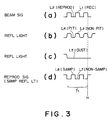
- Figs. 3(a) to (d) show wave forms related to the interruption of information recording operation of the apparatus.
- Fig. 3(a) represents the wave form of a laser beam signal for recording or reproducing information data to or from the medium, in which the level L1 denotes a high signal level required to record an information data and the level L2 denotes a low signal level required to reproduce an information data.
- Fig. 3(b) represents the wave form of a signal of laser light reflected from the medium and indicative of a recorded information pattern, in which the level L3 denotes a high signal level obtained when the laser beam is reflected from the portion other than pits and the level L4 is a low signal level obtained when the laser beam is reflected from a pit, respectively.
- Fig. 3(c) represents the wave form of a signal of laser light reflected from the medium and indicative of the presence of a dust, scratch, stain, etc.
- the level L5 denotes a low level obtained when the laser beam is reflected from a stained or damaged surface of the medium.
- Fig. 3(d) represents the wave form of a signal reproduced from the medium, in which the level L6 denotes a sampled received-light level indicative of that the laser light reflected from the medium is sampled and the level L7 denotes a non-sampled (input-off) level indicative of that the laser light reflected from the medium is not sampled; that is, the reproducing signal is cut off.
- the high level L6 of the sampled received-light level is synchronized with the low level L2 for the data reproduction shown in Fig. 3(a), and the low level L7 of the non-sampled (input-off) level is synchronized with the high level L1 for the data recording shown in Fig. 3(a).
- the high level signal L6 is outputted only when the intensity of the laser light reflected from the medium is lower than a predetermined slice level due to the presence of a pit, dust, scratch, stain, etc., and not outputted when higher than the predetermined slice level due to the absence of a pit, dust, scratch, stain, etc. Therefore, if a pit, dust, scratch, stain, etc. is not present on the surface of the medium, both the levels L6 and L7 become equal to each other.
- the double recording can be prevented as follows: in response to the recording signal as shown in Fig. 3(a), information data are doubly recorded on the medium for a short double recording time period T1 irrespective of the presence or absence of pits. Of course, although the information data are damaged due to the double recording during this short time period T1, the error can be sufficiently relieved by an error correcting circuit.
- the double recording is discriminated on the basis of the reproducing signal (double recording signal) as shown in Fig. 3(d)
- the recording operation is interrupted at an interruption point t1.
- this reproducing signal is generated in the same way even when a dust, scratch, stain, etc. is present on the medium, the recording operation is interrupted. Once interrupted, since the recording operation is kept interrupted, there exists a problem in that it is impossible to resume the recording operation, as long as the recording operation is not restarted manually.
- the object of the present invention is to solve the above-mentioned problem such that the recording operation is kept interrupted when the medium is stained by a dust or damaged with a scratch.
- the optical information recording and reproducing apparatus comprises: detection means for detecting a pseudo double recording signal generated by a dust, scratch, stain, etc. on an information recording medium at a period of an information recording operation; interrupt means for interrupting the information recording operation when said detecting means detects the pseudo double recording signal, to switch the recording operation period to a monitor period; maintain means for maintaining the interruption of the information recording operation when a real double recording signal generated by an information pit is detected at the monitor period; resume means for resuming the information recording operation when the real double recording signal generated by an information pit is not detected at the monitor period; and after the recording operation has been resumed and when the pseudo double recording signal generated by a dust, scratch, stain, etc. still remaining on the medium is detected, the monitor and recording periods being repeated alternately; and after the medium has become free from a dust, scratch, stain, etc. and therefore the real and pseudo double recording signals are not both generated, the recording operation being kept continued normally.
- the recording operation when the real or pseudo double recording operation signal is detected at the recording period, the recording operation is interrupted, and the recording period is switched to the monitor period.
- the recording operation is kept interrupted; and when the pit signal is not detected, the monitor period is returned to the recording period.
- the recording period is switched to the monitor period again.
- the monitor and recording periods are repeated, and after the real and pseudo double recording signals are both not detected during recording period, the normal recording operation is resumed and further kept continued.
- the recording period is switched to the monitor period to discriminate whether the double recording is the real double recording due to the presence of a pit or the pseudo double recording due to the presence of a dust, scratch, stain, etc.
- the recording operation is interrupted; and in the case of the pseudo double recording, the recording operation is kept continued. Therefore, there exists such an effect that it is possible to discriminate the real double recording due to the presence of a pit from the pseudo double recording due to the presence of a dust, scratch, stain, etc. or vice versa, thus eliminating the originally unnecessary interruption of the recording operation.
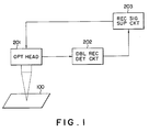
- Fig. 1 is a block diagram showing an embodiment of the present invention.
- information data are recorded on an optical card (medium) 100 by an optical beam emitted from an optical head 201 when the optical card 100 is being reciprocated.
- the optical head 201 transmits a light (e.g. laser) beam with two optical powers of a recording level and a reproducing level alternately to irradiate the medium with a light beam two different power levels.
- the optical head 201 detects the intensity of the light reflected from the medium, and transmits the detected signal to a double recording detection circuit 202.
- the double recording detection circuit 202 When a double recording signal is detected by the double recording detection circuit 202, the double recording detection circuit 202 outputs an interrupt signal to a recording signal supply circuit 203 to interrupt the recording operation of the recording signal supply circuit 203, so that the optical head 201 is switched to a monitor period at which a light beam with a constant optical power of the reproducing level is irradiated upon the medium.
- the double recording detection circuit 202 detects a pit signal, the operation of the recording signal supply circuit 203 is kept interrupted.
- the detection circuit 202 When the double recording detection circuit 202 does not detect a pit signal at the monitor period, the detection circuit 202 outputs a signal to the recording signal supply circuit 203 to return the monitor period to the recording period. That is, the recording signal supply circuit 203 is activated again, so that the optical head 201 starts to irradiate the light beam with two optical powers of the recording level and the reproducing level alternately upon the medium, to continue the information recording operation.
- the double recording detection circuit 202 detects a pseudo double recording signal, so that the optical head 201 is switched to the monitor period again.
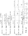
- Figs. 2(a) to (f) show various wave forms of the signals for assistance in explaining the operation of the optical information recording and reproducing apparatus of according to the present invention.
- Fig. 2(a) represents the wave form of a light beam signal for recording or reproducing information data on or from the medium, in which the level L1 denotes a high signal level required to record information data and the level L2 denotes a low signal level required to reproduce an information data.
- Fig. 2(b) represents the wave form of a signal of light reflected from the medium and indicative of a recorded information pattern, in which the level L3 denotes a high signal level obtained when the light beam is reflected form the portion other than pits and the level L4 is a low signal level obtained when the light beam is reflected from a pit, respectively.
- 2(c) is represents the wave form of a signal reproduced from the medium, in which the level L6 denotes a sampled received-light level indicative of that the light reflected from the medium is sampled and the level L7 denotes a non-sampled (input-off) level indicative of that the light reflected from the medium is not sampled; that is, the reproducing signal is cut off.
- the high level L6 of the sampled received-light level is synchronized with the low level L2 for data reproduction shown in Fig. 2(a), and the low level L7 of the non-sampled (input-off) level is synchronized with the high level L1 for data recording shown in Fig. 2(a).
- the high level signal L6 is outputted only when the intensity of the light reflected from the medium is lower than a predetermined slice level due to the presence of a pit, dust, scratch, stain, etc., and not outputted when higher than the predetermined slice level due to the absence of a pit, dust, scratch, stain, etc. Therefore, if a pit, dust, scratch, stain, etc. is not present on the surface of the medium, both the levels L6 and L7 become equal to each other.
- Fig. 2(d) represents the wave form of a signal of a light beam irradiated upon the medium in the same way as in Fig. 2(a)
- Fig. 2(e) represents the wave form of a signal of light reflected from the medium and indicative of the presence of a dust, scratch, stain, etc., in which the level L5 denotes a low level obtained when the light is reflected from a stained or damaged surface of the medium at a low reflection factor.
- Fig. 2(f) represents the wave form of a signal reproduced from the medium, in which the level L61 denotes a sampled received-light level indicative of that the light reflected from the medium is sampled and the level L71 denotes a non-sampled (input-off) level indicative of that the light reflected from the medium is not sampled; that is, the input of the reproducing signal is cut off.
- the recording operation is effected for a short recording period T1.
- the reproducing signal double recording signal
- the double recording is discriminated, and the recording operation is interrupted at the interrupt point t1, and the recording operation is switched to the monitor operation at the period T2.
- the discrimination of whether the double recording is the real double recording or the pseudo double recording can be made on the basis of the reproducing signal obtained after the interrupt point t1 shown in Fig. 2.
- the reproducing signal changes between the two levels L62 and L72 at the monitor period T2 after the interrupt point t1 as shown in Fig. 2(c).
- the pseudo double recording it is possible to obtain the reproducing signal of the constant level L63 at the monitor period T2 as shown in Fig. 2(f).
- the recording operation is interrupted.
- the reproducing signal whose level is constant as shown by the level L63 since the double recording operation is discriminated to be the pseudo operation, the recording operation is resumed at the resume point t2 after the time period T2 has elapsed, thus the monitor period being switched to the recording period again.
- the double recording detection circuit 202 discriminates that the double recording is still kept and therefore interrupts the recording operation, thus the recording period being switched to the monitor period again at another interrupt point t3.
- the apparatus can switch the monitor operation to the normal recording operation after the light beam has passed through the portion damaged by a dust, scratch, stain, etc.
Applications Claiming Priority (2)
| Application Number | Priority Date | Filing Date | Title |
|---|---|---|---|
| JP3345466A JP2948005B2 (ja) | 1991-12-26 | 1991-12-26 | 光学的情報記録再生装置および光学的情報記録方法 |
| JP345466/91 | 1991-12-26 |
Publications (3)
| Publication Number | Publication Date |
|---|---|
| EP0548981A2 true EP0548981A2 (fr) | 1993-06-30 |
| EP0548981A3 EP0548981A3 (en) | 1995-01-25 |
| EP0548981B1 EP0548981B1 (fr) | 1998-03-18 |
Family
ID=18376791
Family Applications (1)
| Application Number | Title | Priority Date | Filing Date |
|---|---|---|---|
| EP92121962A Expired - Lifetime EP0548981B1 (fr) | 1991-12-26 | 1992-12-23 | Appareil d'enregistrement et de reproduction d'information optiques |
Country Status (5)
| Country | Link |
|---|---|
| US (1) | US5301041A (fr) |
| EP (1) | EP0548981B1 (fr) |
| JP (1) | JP2948005B2 (fr) |
| CA (1) | CA2086289C (fr) |
| DE (1) | DE69224804T2 (fr) |
Cited By (2)
| Publication number | Priority date | Publication date | Assignee | Title |
|---|---|---|---|---|
| EP0718831A2 (fr) * | 1994-12-20 | 1996-06-26 | Matsushita Electric Industrial Co., Ltd | Procédé d'enregistrement et lecture d'un milieu d'enregistrement optique d'information |
| EP0847046A2 (fr) * | 1994-12-20 | 1998-06-10 | Matsushita Electric Industrial Co., Ltd | Relation variable entre le signal et l'espacement sur un support d'enregistrement optique |
Families Citing this family (3)
| Publication number | Priority date | Publication date | Assignee | Title |
|---|---|---|---|---|
| US6256146B1 (en) | 1998-07-31 | 2001-07-03 | 3M Innovative Properties | Post-forming continuous/disperse phase optical bodies |
| JP2001344756A (ja) * | 2000-05-30 | 2001-12-14 | Ricoh Co Ltd | 情報記録装置 |
| US7583440B2 (en) * | 2006-06-05 | 2009-09-01 | Skc Haas Display Films Co., Ltd. | Diffusely-reflecting polarizer having nearly isotropic continuous phase |
Citations (4)
| Publication number | Priority date | Publication date | Assignee | Title |
|---|---|---|---|---|
| EP0182127A2 (fr) * | 1984-11-19 | 1986-05-28 | International Business Machines Corporation | Système pour la prévention d'écrasement des données écrites par voie optique antérieurement et pour l'écriture pendant l'enregistrement des données écrite par voie optique |
| EP0420215A2 (fr) * | 1989-09-29 | 1991-04-03 | Kabushiki Kaisha Toshiba | Appareil pour l'enregistrement optique d'information sur un support d'enregistrement |
| EP0420252A2 (fr) * | 1989-09-29 | 1991-04-03 | Kabushiki Kaisha Toshiba | Système d'enregistrement d'information |
| US5060218A (en) * | 1987-11-16 | 1991-10-22 | Olympus Optical Co., Ltd. | Write-once type optical recording/reproducing device |
Family Cites Families (5)
| Publication number | Priority date | Publication date | Assignee | Title |
|---|---|---|---|---|
| JPS59145726U (ja) * | 1983-03-16 | 1984-09-28 | パイオニア株式会社 | 情報読取装置におけるサ−ボ装置 |
| JPS6314329A (ja) * | 1986-07-07 | 1988-01-21 | Dainippon Printing Co Ltd | 可撓性レ−ザ−デイスクの再生方法 |
| JPS6316422A (ja) * | 1986-07-08 | 1988-01-23 | Nec Corp | 光デイスク装置 |
| US5184343A (en) * | 1991-05-06 | 1993-02-02 | Johann Donald F | Compensation for dust on an optical disk by increasing laser writing power |
| KR940002573B1 (ko) * | 1991-05-11 | 1994-03-25 | 삼성전자 주식회사 | 광디스크기록재생장치에 있어서 연속재생장치 및 그 방법 |
-
1991
- 1991-12-26 JP JP3345466A patent/JP2948005B2/ja not_active Expired - Fee Related
-
1992
- 1992-12-22 US US07/994,945 patent/US5301041A/en not_active Expired - Lifetime
- 1992-12-23 DE DE69224804T patent/DE69224804T2/de not_active Expired - Fee Related
- 1992-12-23 EP EP92121962A patent/EP0548981B1/fr not_active Expired - Lifetime
- 1992-12-24 CA CA002086289A patent/CA2086289C/fr not_active Expired - Fee Related
Patent Citations (4)
| Publication number | Priority date | Publication date | Assignee | Title |
|---|---|---|---|---|
| EP0182127A2 (fr) * | 1984-11-19 | 1986-05-28 | International Business Machines Corporation | Système pour la prévention d'écrasement des données écrites par voie optique antérieurement et pour l'écriture pendant l'enregistrement des données écrite par voie optique |
| US5060218A (en) * | 1987-11-16 | 1991-10-22 | Olympus Optical Co., Ltd. | Write-once type optical recording/reproducing device |
| EP0420215A2 (fr) * | 1989-09-29 | 1991-04-03 | Kabushiki Kaisha Toshiba | Appareil pour l'enregistrement optique d'information sur un support d'enregistrement |
| EP0420252A2 (fr) * | 1989-09-29 | 1991-04-03 | Kabushiki Kaisha Toshiba | Système d'enregistrement d'information |
Cited By (11)
| Publication number | Priority date | Publication date | Assignee | Title |
|---|---|---|---|---|
| EP0718831A2 (fr) * | 1994-12-20 | 1996-06-26 | Matsushita Electric Industrial Co., Ltd | Procédé d'enregistrement et lecture d'un milieu d'enregistrement optique d'information |
| EP0718831A3 (fr) * | 1994-12-20 | 1997-05-21 | Matsushita Electric Ind Co Ltd | Procédé d'enregistrement et lecture d'un milieu d'enregistrement optique d'information |
| EP0843305A2 (fr) * | 1994-12-20 | 1998-05-20 | Matsushita Electric Industrial Co., Ltd | Procédé d'enregistrement optique à variation d'intensité lumineuse |
| EP0847046A2 (fr) * | 1994-12-20 | 1998-06-10 | Matsushita Electric Industrial Co., Ltd | Relation variable entre le signal et l'espacement sur un support d'enregistrement optique |
| EP0843305A3 (fr) * | 1994-12-20 | 1998-07-01 | Matsushita Electric Industrial Co., Ltd | Procédé d'enregistrement optique à variation d'intensité lumineuse |
| EP0847046A3 (fr) * | 1994-12-20 | 1998-07-01 | Matsushita Electric Industrial Co., Ltd | Relation variable entre le signal et l'espacement sur un support d'enregistrement optique |
| US6031814A (en) * | 1994-12-20 | 2000-02-29 | Matsushita Electric Industrial Co., Ltd. | Optical disk with stop-pulse generating means in a guide groove |
| US6487151B1 (en) | 1994-12-20 | 2002-11-26 | Matsushita Electric Industrial Co. Ltd. | Optical information recording and reproducing system with overwrite capability and recording medium for use therewith |
| US6683739B2 (en) | 1994-12-20 | 2004-01-27 | Matsushita Electric Industrial Co., Ltd. | Optical information recording and reproducing system with overwrite capability and recording medium for use therewith |
| US6697313B2 (en) | 1994-12-20 | 2004-02-24 | Matsushita Electric Industrial Co., Ltd. | Optical information recording and reproducing system with overwrite capability and recording medium for use therewith |
| US6707776B2 (en) | 1994-12-20 | 2004-03-16 | Matsushita Electric Industrial Co., Ltd. | Recording and reproducing method of optical information recording medium |
Also Published As
| Publication number | Publication date |
|---|---|
| JP2948005B2 (ja) | 1999-09-13 |
| CA2086289C (fr) | 1997-05-20 |
| CA2086289A1 (fr) | 1993-06-27 |
| EP0548981B1 (fr) | 1998-03-18 |
| EP0548981A3 (en) | 1995-01-25 |
| DE69224804T2 (de) | 1998-08-27 |
| JPH05182197A (ja) | 1993-07-23 |
| DE69224804D1 (de) | 1998-04-23 |
| US5301041A (en) | 1994-04-05 |
Similar Documents
| Publication | Publication Date | Title |
|---|---|---|
| AU4554489A (en) | Method and apparatus for controlling and detecting recording laser beam | |
| MY130581A (en) | Write once optical disc recording apparatus | |
| JP3109708B2 (ja) | 光学的情報記録再生装置 | |
| EP0548981A2 (fr) | Appareil d'enregistrement et de reproduction d'information optiques | |
| US5682366A (en) | Optical disc recording apparatus with efficient data checking | |
| JPH01201831A (ja) | 光学的情報記録再生装置 | |
| JPH05258379A (ja) | 信号再生方式 | |
| JPH03181024A (ja) | 光学式ディスク装置 | |
| JPS57167142A (en) | Optical recording and reproducing device | |
| US5181196A (en) | Erase mark detecting circuit for detecting an erase mark superimposed on data recorded on a sector of an optical recording medium | |
| KR100331339B1 (ko) | 광디스크의 헤더영역 보호방법 및 장치 | |
| JPH04209323A (ja) | 光学的情報記録/再生装置の読取り信号処理回路 | |
| JPH0883465A (ja) | 光ディスク再生装置 | |
| EP0599387B1 (fr) | Dispositif de lecture/écriture magnétooptique | |
| JP2951126B2 (ja) | 光学的情報記録再生装置 | |
| JPS637522A (ja) | トラツク飛び検出装置 | |
| JPS61158079A (ja) | 光学式情報記録再生装置 | |
| JPH0444328B2 (fr) | ||
| JPH07169201A (ja) | 光ディスク記録装置 | |
| JPS63213130A (ja) | トラツクはずれ検出回路 | |
| JP2002032958A (ja) | 再生信号処理回路 | |
| KR980004736A (ko) | 광디스크 재생시스템의 에러검출장치 | |
| JPH0729195A (ja) | 光ディスクプレーヤーのサーボ異常誤検出防止回路 | |
| JPH02301019A (ja) | 光学式記録装置 | |
| JPS63249938A (ja) | 光デイスク装置における記録可能領域判別装置 |
Legal Events
| Date | Code | Title | Description |
|---|---|---|---|
| PUAI | Public reference made under article 153(3) epc to a published international application that has entered the european phase |
Free format text: ORIGINAL CODE: 0009012 |
|
| 17P | Request for examination filed |
Effective date: 19930113 |
|
| AK | Designated contracting states |
Kind code of ref document: A2 Designated state(s): DE FR GB IT |
|
| PUAL | Search report despatched |
Free format text: ORIGINAL CODE: 0009013 |
|
| AK | Designated contracting states |
Kind code of ref document: A3 Designated state(s): DE FR GB IT |
|
| 17Q | First examination report despatched |
Effective date: 19950219 |
|
| GRAG | Despatch of communication of intention to grant |
Free format text: ORIGINAL CODE: EPIDOS AGRA |
|
| GRAG | Despatch of communication of intention to grant |
Free format text: ORIGINAL CODE: EPIDOS AGRA |
|
| GRAH | Despatch of communication of intention to grant a patent |
Free format text: ORIGINAL CODE: EPIDOS IGRA |
|
| GRAH | Despatch of communication of intention to grant a patent |
Free format text: ORIGINAL CODE: EPIDOS IGRA |
|
| GRAA | (expected) grant |
Free format text: ORIGINAL CODE: 0009210 |
|
| AK | Designated contracting states |
Kind code of ref document: B1 Designated state(s): DE FR GB IT |
|
| PG25 | Lapsed in a contracting state [announced via postgrant information from national office to epo] |
Ref country code: IT Free format text: LAPSE BECAUSE OF FAILURE TO SUBMIT A TRANSLATION OF THE DESCRIPTION OR TO PAY THE FEE WITHIN THE PRE;WARNING: LAPSES OF ITALIAN PATENTS WITH EFFECTIVE DATE BEFORE 2007 MAY HAVE OCCURRED AT ANY TIME BEFORE 2007. THE CORRECT EFFECTIVE DATE MAY BE DIFFERENT FROM THE ONE RECORDED.SCRIBED TIME-LIMIT Effective date: 19980318 |
|
| REF | Corresponds to: |
Ref document number: 69224804 Country of ref document: DE Date of ref document: 19980423 |
|
| ET | Fr: translation filed | ||
| PLBE | No opposition filed within time limit |
Free format text: ORIGINAL CODE: 0009261 |
|
| STAA | Information on the status of an ep patent application or granted ep patent |
Free format text: STATUS: NO OPPOSITION FILED WITHIN TIME LIMIT |
|
| 26N | No opposition filed | ||
| REG | Reference to a national code |
Ref country code: GB Ref legal event code: IF02 |
|
| PGFP | Annual fee paid to national office [announced via postgrant information from national office to epo] |
Ref country code: GB Payment date: 20051221 Year of fee payment: 14 |
|
| PGFP | Annual fee paid to national office [announced via postgrant information from national office to epo] |
Ref country code: FR Payment date: 20051228 Year of fee payment: 14 |
|
| PGFP | Annual fee paid to national office [announced via postgrant information from national office to epo] |
Ref country code: DE Payment date: 20060213 Year of fee payment: 14 |
|
| PG25 | Lapsed in a contracting state [announced via postgrant information from national office to epo] |
Ref country code: DE Free format text: LAPSE BECAUSE OF NON-PAYMENT OF DUE FEES Effective date: 20070703 |
|
| GBPC | Gb: european patent ceased through non-payment of renewal fee |
Effective date: 20061223 |
|
| REG | Reference to a national code |
Ref country code: FR Ref legal event code: ST Effective date: 20070831 |
|
| PG25 | Lapsed in a contracting state [announced via postgrant information from national office to epo] |
Ref country code: GB Free format text: LAPSE BECAUSE OF NON-PAYMENT OF DUE FEES Effective date: 20061223 |
|
| PG25 | Lapsed in a contracting state [announced via postgrant information from national office to epo] |
Ref country code: FR Free format text: LAPSE BECAUSE OF NON-PAYMENT OF DUE FEES Effective date: 20070102 |