EP0548718A2 - Dispositif d'embrayage pour véhicules - Google Patents
Dispositif d'embrayage pour véhicules Download PDFInfo
- Publication number
- EP0548718A2 EP0548718A2 EP92121211A EP92121211A EP0548718A2 EP 0548718 A2 EP0548718 A2 EP 0548718A2 EP 92121211 A EP92121211 A EP 92121211A EP 92121211 A EP92121211 A EP 92121211A EP 0548718 A2 EP0548718 A2 EP 0548718A2
- Authority
- EP
- European Patent Office
- Prior art keywords
- pressure
- master cylinder
- slave cylinder
- clutch
- clutch pedal
- Prior art date
- Legal status (The legal status is an assumption and is not a legal conclusion. Google has not performed a legal analysis and makes no representation as to the accuracy of the status listed.)
- Granted
Links
Images



Classifications
-
- F—MECHANICAL ENGINEERING; LIGHTING; HEATING; WEAPONS; BLASTING
- F16—ENGINEERING ELEMENTS AND UNITS; GENERAL MEASURES FOR PRODUCING AND MAINTAINING EFFECTIVE FUNCTIONING OF MACHINES OR INSTALLATIONS; THERMAL INSULATION IN GENERAL
- F16D—COUPLINGS FOR TRANSMITTING ROTATION; CLUTCHES; BRAKES
- F16D48/00—External control of clutches
- F16D48/02—Control by fluid pressure
-
- F—MECHANICAL ENGINEERING; LIGHTING; HEATING; WEAPONS; BLASTING
- F16—ENGINEERING ELEMENTS AND UNITS; GENERAL MEASURES FOR PRODUCING AND MAINTAINING EFFECTIVE FUNCTIONING OF MACHINES OR INSTALLATIONS; THERMAL INSULATION IN GENERAL
- F16D—COUPLINGS FOR TRANSMITTING ROTATION; CLUTCHES; BRAKES
- F16D48/00—External control of clutches
- F16D48/06—Control by electric or electronic means, e.g. of fluid pressure
- F16D48/066—Control of fluid pressure, e.g. using an accumulator
-
- F—MECHANICAL ENGINEERING; LIGHTING; HEATING; WEAPONS; BLASTING
- F16—ENGINEERING ELEMENTS AND UNITS; GENERAL MEASURES FOR PRODUCING AND MAINTAINING EFFECTIVE FUNCTIONING OF MACHINES OR INSTALLATIONS; THERMAL INSULATION IN GENERAL
- F16D—COUPLINGS FOR TRANSMITTING ROTATION; CLUTCHES; BRAKES
- F16D48/00—External control of clutches
- F16D48/02—Control by fluid pressure
- F16D2048/0209—Control by fluid pressure characterised by fluid valves having control pistons, e.g. spools
-
- F—MECHANICAL ENGINEERING; LIGHTING; HEATING; WEAPONS; BLASTING
- F16—ENGINEERING ELEMENTS AND UNITS; GENERAL MEASURES FOR PRODUCING AND MAINTAINING EFFECTIVE FUNCTIONING OF MACHINES OR INSTALLATIONS; THERMAL INSULATION IN GENERAL
- F16D—COUPLINGS FOR TRANSMITTING ROTATION; CLUTCHES; BRAKES
- F16D48/00—External control of clutches
- F16D48/02—Control by fluid pressure
- F16D2048/0215—Control by fluid pressure for damping of pulsations within the fluid system
-
- F—MECHANICAL ENGINEERING; LIGHTING; HEATING; WEAPONS; BLASTING
- F16—ENGINEERING ELEMENTS AND UNITS; GENERAL MEASURES FOR PRODUCING AND MAINTAINING EFFECTIVE FUNCTIONING OF MACHINES OR INSTALLATIONS; THERMAL INSULATION IN GENERAL
- F16D—COUPLINGS FOR TRANSMITTING ROTATION; CLUTCHES; BRAKES
- F16D2300/00—Special features for couplings or clutches
- F16D2300/22—Vibration damping
-
- Y—GENERAL TAGGING OF NEW TECHNOLOGICAL DEVELOPMENTS; GENERAL TAGGING OF CROSS-SECTIONAL TECHNOLOGIES SPANNING OVER SEVERAL SECTIONS OF THE IPC; TECHNICAL SUBJECTS COVERED BY FORMER USPC CROSS-REFERENCE ART COLLECTIONS [XRACs] AND DIGESTS
- Y10—TECHNICAL SUBJECTS COVERED BY FORMER USPC
- Y10T—TECHNICAL SUBJECTS COVERED BY FORMER US CLASSIFICATION
- Y10T137/00—Fluid handling
- Y10T137/7722—Line condition change responsive valves
- Y10T137/7758—Pilot or servo controlled
- Y10T137/7761—Electrically actuated valve
Definitions
- the invention relates to a coupling device for vehicles according to the preamble of claims 1 and 5 respectively.
- the clutch is hydraulically separated by depressing the clutch pedal via the master cylinder and the slave cylinder connected to it.
- the clutch device When starting, the clutch device must transmit the required engine torque if there is a speed difference between the crankshaft and the transmission shaft. This takes place during the closing process of the clutch device and requires the driver to have a balanced feeling for the operating speed of the clutch device as a function of the gear engaged and of the accelerator pedal position from which the engine torque results.
- the coupling device (DE-OS 37 36 584) is a safety device in the form of a in the line connection from the master cylinder to the slave cylinder Closure body arranged. It has axial grooves on the circumference through which the fluid can flow when the clutch pedal is actuated. In addition, the closure body is axially penetrated by a bore which forms a throttle point. At undesirably high coupling speeds, the fluid builds up on the end face of the closure body and presses it against the force of a spring into a closed position in which its end face rests on the housing wall. As a result, the axial grooves are closed, so that the fluid can only pass through the throttle point when flowing back from the slave cylinder to the master cylinder.
- Another coupling device is known (DE-GM 17 85 882), in which the fluid can always flow throttled from the master cylinder to the slave cylinder and back during the coupling and uncoupling phase of the coupling. If the hydraulic medium flows back from the slave cylinder, a throttle disc is first brought into contact with the cylinder base. The consequence of this is that the hydraulic medium can only flow through the throttle point of the throttle disc into the feed line to the master cylinder. This throttling effect always occurs when the clutch pedal is released.
- the invention has for its object the generic To design the coupling device so that when the clutch pedal is suddenly released, the main flow path via the fluid from the slave cylinder to the master cylinder is suddenly closed.
- the two pressure switches grab the pressure before and after the orifice.
- the differential pressure is characteristic of the flow rate of the fluid. If the clutch pedal is released suddenly, the limit speed of the fluid characteristic is exceeded. As a result, the piston of the master cylinder is returned very quickly. A negative pressure is created in the master cylinder, which is immediately noticeable on the measuring orifice.
- the solenoid valve is actuated, which instantly moves the closure body into its closed position. As a result, the main flow path for the fluid from the slave cylinder to the master cylinder is interrupted, so that the fluid can only flow through the throttle point. As a result, the fluid flows through the clutch pedal into the master cylinder only with a delay, despite the lack of counterforce, so that the clutch is properly closed even when the clutch pedal is released.
- the closure body is held by the disc spring in its position holding the measuring aperture open.
- the fluid can flow quickly from the slave cylinder to the master cylinder. If the clutch pedal is released suddenly, then the pressure drop across the cross section of the throttle point is so great that the force on the opposite side of the closure body predominates due to a corresponding pressure drop on the side of the plate spring.
- the closure body can be moved at high switching speed against the force of the plate spring, so that it suddenly blocks the main flow path for the fluid. As a result, it can only flow from the slave cylinder to the master cylinder via the throttling point.
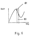
- the rapid closing process is achieved in that the plate spring is set so that its working area lies in the falling part of its force-displacement characteristic. Due to the special design of the plate spring, the coupling device can thus be adjusted so that the closure body is suddenly moved into its closed position.
- Fig. 1 shows a conventional fluid-operated coupling device.
- a clutch housing 1 which is flanged to an engine block 2
- a drive plate 3 which has an annular friction lining 4 and 5 on the outer edge on both sides.
- the drive plate 3 is seated on a bushing 6 and lies between a mass flywheel 7 and a pressure plate 8.
- a disc spring 9 presses the pressure plate 8, the mass flywheel 7 and the drive plate 3 together, as a result of which the power transmission via the clutch from the transmission shaft 10 to the crankshaft 11 is closed is.
- a hydraulically-mechanically actuated release bearing 12 which is axially displaceably seated on a guide 13 of the clutch housing 1, the pressure plate 8 can be relieved of the plate spring 9, e.g.
- the release bearing 12 has a radially outwardly directed flange 14, on which a one-armed lever 15 can engage for the axial displacement of the release bearing 12. It is pivotally mounted in the clutch housing 1 about an axis 16. At the end opposite the pivot axis 16, a piston rod 17 of a slave cylinder 18 acts on the lever 15, the pressure chamber 19 of which is connected via a line 20 to a pressure chamber 21 of a master cylinder 22. Its piston rod 22 protrudes from the cylinder housing and rests on a clutch pedal 24 of the vehicle.
- Fig. 1 shows the position when the clutch pedal 24 is not depressed, ie the clutch is closed.
- the clutch pedal 24 pressed.
- the piston rod 23 is displaced into the master cylinder 22, as a result of which the hydraulic medium in the pressure chamber flows via the line 20 into the pressure chamber 19 of the slave cylinder 18 provided on the clutch housing 1, the piston 25 of which is seated on the piston rod 17 is thereby pushed into the clutch housing 1.
- the lever 15 thereby pivots counterclockwise and displaces the bush-shaped release bearing 12. This relieves the pressure plate 8 in a known manner from the plate spring 9, so that the clutch is opened and thus the drive connection between the crankshaft 11 and the transmission shaft 10 is interrupted.
- the clutch grinds and bridges the speed difference between the crankshaft 11 and the transmission shaft 10.
- the clutch must therefore transfer the required engine torque at this speed difference with slip. This takes place during the clutch closing process and requires the driver to have a balanced feeling for the clutch actuation speed depending on the gear engaged and the accelerator pedal position from which the engine torque results.
- the pressure in the hydraulic system continues to decrease. If the clutch pedal 24 is now gradually released, the pressure initially rises again. At point 28 the clutch begins to close again, i.e. the lever 15 pivots under the pressure of the again tensioning plate spring 9 clockwise around the axis 16 and thereby presses the piston rod 17 of the slave cylinder 18 back.
- the pressure-displacement characteristic of the fluid-operated clutch is predetermined by the design of the plate spring 9.
- the coupling point moves according to the state of wear 28 or the separating point 27 on the characteristic curve to the right. However, since the characteristic curve is almost horizontal in this area, the actuating force remains almost constant over the distance.
- the safety device 37 shown in FIG. 4 is provided. With it, the clutch speed is detected and the fluid flow between the slave cylinder 18 and the master cylinder 22 throttled so that the pressure drop is within the range 35 (Fig. 3) of the pressure-time characteristic. This ensures that drive train parts are not damaged, even if the foot should accidentally slip off the clutch pedal 24.
- the safety device is designed so that the normal operating procedures when coupling, such as fast, sporty coupling and switching, are not affected. The safety device only operates when the described strong pressure drop occurs.
- the safety device 37 is installed in the area 20 between the slave cylinder 18 and the master cylinder 22. It has a magnetic coil 38 which is surrounded by a cover cap 39.
- the magnet coil 38 surrounds a pole core tube 40 in which a magnet armature 41 is axially displaceable is arranged. It is displaceable against the force of a compression spring 42 when the solenoid 38 is subjected to a storm.
- the compression spring 42 surrounds a plunger 43 which is fixedly connected to the magnet armature 41, the free end of which is conical and which cooperates with a passage bore 44 which is provided in a base body 45 of the safety device.
- the passage bore 44 connects two fluid spaces 46 and 47 to one another.
- the plunger 43 protrudes into the fluid space 46, while a pressure spring 48 is accommodated in the fluid space 47, with which a check valve plate 49 is pressed into its closed position.
- the bottom 50 of the fluid space 47 facing away from the fluid space 46 has a central elevation 51, on which the check valve plate 49 rests.
- the elevation 51 is penetrated by a bore 52 which is kept closed by the valve plate 49.
- the passage bore 44 has a smaller cross section than the two fluid spaces 46 and 47.
- the bore 52 which, like the fluid spaces 46, 47, is arranged centrally in the base body 45, is connected via a transverse bore 53 to a parallel bore 54. It connects the fluid space 46 to a low-pressure switch 55, which is accommodated in the base body 45 of the safety device 37.
- the bore 54 is connected to a connection 56 for the master cylinder 22.
- the fluid space 47 is connected via a transverse bore 57 in the base body 45 to a connection 58 for the slave cylinder 18.
- the transverse bore 57 is connected via a longitudinal bore 59 to a high-pressure switch 60 arranged in the base body 45.
- the cap 39 On the base body 45, the cap 39 is attached at one end and a cover 61 is fastened at the opposite end, through which an electrical connection cable 62 for the pressure switches 55 and 60 and for the magnet coil 38 is guided centrally.
- the hydraulic medium flows from the master cylinder 22 and the connection 56 of the safety device 37 into the bore 54. From there it flows through the transverse bore 53 and the bore 52 into the fluid space 47.
- the check valve plate 49 is under the pressure of the Hydraulic medium lifted from its seat 51 against the force of the compression spring 48. Thus, the hydraulic medium can freely interfere with the cross bore 57 to the connection 58 of the slave cylinder 18.
- the check valve plate 49 and the elevation 51 form a check valve which allows the hydraulic medium to flow freely from the connection 56 to the connection 58 for quick disconnection of the coupling.
- the hydraulic medium can also flow from the connection 56 through the bore 54 into the fluid space 46 and from there through the passage bore 44 into the fluid space 47.
- the magnet armature 41 is under the force of the return spring 42 in its stop-limited end position shown in FIG. 4, in which the plunger 43 is at a distance from the inlet opening of the through bore 44.
- This part of the safety device 37 forms a measuring orifice which is dimensioned so that the coupling speed is not reduced in the normal operating characteristic field 35 (FIG. 3).
- the safety device 37 is designed such that signals are derived from the speed of the hydraulic flow.
- the pressure switches 55 and 60 are used for this purpose, the design of which is known per se. They are arranged upstream and downstream of the orifice 44 in the direction of flow of the hydraulic medium and tap the differential pressure of the hydraulic medium, which is characteristic of the flow velocity, via this orifice plate. As already explained, this orifice 44 is dimensioned so that the coupling speed is not reduced when the clutch pedal 24 is properly operated.
- the pressures in front of and behind the orifice plate 43, 44 are tapped via the pressure switches 55, 60.
- the pressure switch 60 acts as a make contact and the pressure switch 55 as a break contact.
- the electrically connected pressure switches 55, 60 control the solenoid valve 38, 41, 43, with which the line 20 between the master cylinder 22 and the slave cylinder 18 can be separated behind the measuring orifice 44.
- the solenoid valve 38, 41, 43 remains in the flow position shown in FIG. 4, in which the plunger 43 does not close the passage bore 44.
- the two switches 55 and 60 are arranged and designed such that the high pressure switch 60 is closed at a system pressure of, for example, more than 18 bar, while the low pressure switch 55 is open at this pressure. Since these two switches 55 and 60 lie one behind the other in the circuit to the solenoid valve 38, 41, 43 (FIG. 9), the current path to the solenoid valve is opened as a result of the open switch 55.
- the solenoid valve therefore assumes its open position, i.e. the orifice 44 is open. As a result, the hydraulic medium can flow freely through the open measuring orifice 44.
- the check valve 49, 51 forms a throttle orifice through which the hydraulic medium must now flow.
- the end face of the elevation 51 and / or the support side of the check valve plate 49 is provided with a depression or elevation 49 ', as a result of which a passage for the hydraulic medium is formed even when the check valve plate 49 rests on the elevation 51.
- the check valve plate 49 can also be provided with a bore passing through it.
- the hydraulic medium ejected by the slave cylinder 18 now flows via the transverse bore 57 into the fluid space 47 and from there through the described throttle point between the check valve plate 49 and the elevation 51 into the bore 52. From there the hydraulic medium flows through the transverse bore 53 and the bore 54 to Connection 56 of the master cylinder 22.
- the throttle point 49, 51 has such a dimensioning that the predetermined limit speed (line 36 'of the pressure-time diagram according to FIG. 3) is not exceeded during a clutch closing operation in which the clutch pedal 24 is released and therefore no restoring force acts.
- the closing speed moves in the area 35 of the pressure-time diagram according to FIG. 3, so that torque peaks do not occur and therefore there is no fear of damage to parts of the drive train.
- the hydraulic medium can only flow with a delay into the master cylinder 22 despite the lack of counterforce by the clutch pedal 24, so that the clutch is properly closed even when the clutch pedal 24 is released.
- the pressure in the slave cylinder 18 is reduced continuously and slowly until the threshold value of the high-pressure switch 60, in the exemplary embodiment 18 bar, is reached. As soon as this value is undershot, this high-pressure switch 60 opens and thus interrupts the current connection to the solenoid valve 38, 41, 43. The magnet armature 41 is then returned to its starting position by the force of the return spring 42, as a result of which the measuring orifice 44 is opened again. The hydraulic medium can therefore now flow freely again from the slave cylinder 18 via the measuring orifice 44 to the master cylinder 22.
- the threshold value of the high-pressure switch 60 in the exemplary embodiment 18 bar
- the safety device 37 described reliably prevents the clutch from suddenly closing when the clutch pedal 24 is suddenly released becomes. If this occurs, the through bore 44 is immediately closed via the pressure switches 55, 60, so that the hydraulic medium can only flow from the connection 58 to the connection 56 via the throttle point 49, 51. This closes the clutch at the desired low speed. As long as the driver operates the clutch pedal 24 properly, the safety device 37 does not come into force because the pressure difference in front of and behind the passage bore 44 (measuring orifice) is approximately the same and so the pressure drop is not greater than the pressure difference of the setting values of the two pressure switches 55, 60 .
- the safety device operates in the manner described at three speeds when coupling with the clutch pedal 24 released.
- the first speed is determined via the measuring orifice 44 at a full pressure drop as a result of the fully tensioned disk spring 9 when the clutch is fully open.
- the second speed is determined by the throttle point 49, 51.
- the third speed is determined by the steadily decreasing pressure drop across the orifice plate 44 as a result of the relaxing plate spring 9 after the pressure drop across the orifice plate 44 falls below a predetermined threshold value and the clutch-technical feeling when the clutch pedal 24 is actuated is maintained.
- FIG. 5 shows a second embodiment of a safety device 37a, which only works at two speeds when coupling in the region of impermissible speeds.
- This embodiment is designed so that it influences the hydraulic flow without the use and installation of electrical components.
- the pressure switches are missing 55, 60.
- the safety device 37a has the base body 45a, which has the connection 56a for the master cylinder 22 and the connection 58a for the slave cylinder 18.
- a switching piston 63 is axially displaceable in the base body 45a. It is under the force of a plate spring 64, which presses it into the starting position shown in FIG. 5, in which the switching piston 63 rests on an adjusting screw 65 which is screwed into the base body 45a.
- the base body 45a is provided with a second adjusting screw 66 at the opposite end. With the two adjusting screws 65, 66, the axial position of the switching piston 63 can be precisely determined.
- connection 56a opens into a fluid chamber 67, in which the plate spring 64 is also arranged, which is supported on the bottom 68 of the fluid chamber.
- the switching piston 63 is provided with a central bore 69 which opens into the end face of the switching piston facing the adjusting screw 65.
- the bore 69 extends into a fluid space 70, which is connected by a longitudinal bore 71, which is small in cross section, to a diametrical bore 72, which connects two diametrically opposed longitudinal grooves 73 and 74 of the switching piston.
- These longitudinal grooves 73, 74 are delimited on the outside by the inner wall 75a.
- the longitudinal grooves 73, 74 are connected via a throttle cross section 76 to a fluid space 77, into which the connection 58a of the slave cylinder 18 opens.
- the longitudinal grooves 73, 74 are connected to the through a flow opening 78 Fluid chamber 67 connected.
- the longitudinal bore 69 of the switching piston 63 is penetrated by a transverse bore 79 which connects this longitudinal bore to the fluid space 77.
- the longitudinal bore 69 has a smaller cross section than the fluid space 70 in the switching piston 63, but a larger cross section than the longitudinal bore 71 of the switching piston.
- the longitudinal bore 71 is closed by a check valve plate 49a, which in turn is under the force of the compression spring 48a.
- the check valve plate 49a in turn rests on an elevation 51a through which the longitudinal bore 71 passes.
- the end face of the elevation 51 and / or the support side of the check valve plate 49a are provided in accordance with the previous exemplary embodiment with at least one depression and / or elevation through which the hydraulic medium can flow in a manner to be described if the clutch pedal 24 is released unintentionally.
- the switching piston 63 is in the switching position shown in FIG. 5, into which it is pressed by the plate spring 64. If the clutch pedal 24 is actuated, the hydraulic medium flows from the master cylinder 22 via the connection 56a into the fluid chamber 67. From there it flows into the fluid chamber 70 via the flow opening 78, the transverse bore 72 and the longitudinal bore 71 via the open check valve 59a, 51a here it can flow freely into the longitudinal bore 69 and the transverse bore 79 to the connection 58a of the slave cylinder 18.
- the hydraulic medium flows from the flow opening 78 via the longitudinal grooves 73, 74 and the throttle cross-section 76 into the fluid space 77, from which the hydraulic medium also leads to the connection 58a of the Slave cylinder 18 can flow. In this way, a quick disconnection of the coupling is guaranteed, since the hydraulic medium can flow freely.
- the check valve 49a, 51a allows the hydraulic medium to flow unhindered from the connection 56a in the manner described to the slave connection 58a.
- Fig. 6 shows the force-displacement characteristic of a plate spring.
- the plate spring 64 is set so that the working area 80 results in the force-displacement diagram. If the switching piston 63 is in the switching position according to FIG. 5, then the point 81 results on the force-displacement characteristic. If the switching piston 63 is moved from its switching position in the manner described, the force of the plate spring 64 decreases in accordance with the force-displacement characteristic. As a result, the switching piston 63 remains in its adjusted position under the acting hydraulic pressure.
- the hydraulic medium coming from the slave cylinder 18 can no longer flow through the throttle cross sections 76, since they are closed as a result of the shifting switching piston 63.
- the hydraulic medium can only flow into the fluid chamber 70 of the switching piston 63 via the transverse bore 79 or the longitudinal bore 69. From there it can via the throttle point, which are formed as a result of the depressions and / or increases in the check valve plate 49a and / or the elevation 51, into the longitudinal bore 71, the transverse bore 72 and the flow openings 78 into the fluid space 67 and from there to the transmitter connection Stream 56a.
- the driver notices through the lack of feeling in the coupling foot that an operating error has occurred during coupling.
- the safety device works 37a with only two speeds. Via the orifice 76 (throttle cross section), the first speed is determined at a full pressure drop due to the fully tensioned disc spring 64 when the clutch is fully open. The second speed results from the fact that the switching piston 63 is shifted out of its switching position when the clutch pedal 24 is suddenly released, and the clutch speed is thereby determined by the throttle point on the check valve 49a, 51a during the coupling process.
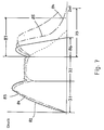
- Fig. 7 shows the pressure-time diagram of the coupling process.
- the solid line 82 indicates the pressure curve without a built-in safety device 37a. This course of the characteristic curve corresponds to the diagram according to FIG. 3.
- the three areas 31 to 33 are again recognizable, those for opening the clutch (area 31), for keeping the clutch separate (area 32) and for closing the clutch (area 33 ) are decisive.
- Fig. 7 the case is drawn in that the clutch pedal 24 is suddenly released. As a result, the pressure in the system decreases at the fastest possible speed.
- the dotted line 83 denotes the pressure in the master cylinder 22 when the safety device 37a is installed
- the dash-dotted curve 84 denotes the pressure in the slave cylinder 18 when the safety device is installed.
- the two characteristic curves 83 and 84 show the case in which the clutch pedal 24 is suddenly released. As a result of the safety device 37a, the pressure in the system does not drop suddenly, but rather drops gradually.
- the dash-dotted characteristic curve 85 shows the pressure in the slave cylinder 18 when the clutch is operated properly.
- the speed of the clutch pedal 24 is noticeably influenced by the throttle point 76. It is no longer determined by the foot.
- the diagram according to FIG. 7 shows that if the clutch pedal 24 is not operated properly and without the safety device 37a, only the area 86 is available in the characteristic field 33, which is significantly smaller than the area 87 when the safety device 37a is installed. A comparison of the two areas 86 and 87 shows that the safety device 37a nevertheless slows down the closing speed of the clutch sufficiently when the clutch pedal 24 is suddenly released, so that damage to drive train parts is excluded.
Landscapes
- Engineering & Computer Science (AREA)
- General Engineering & Computer Science (AREA)
- Physics & Mathematics (AREA)
- Fluid Mechanics (AREA)
- Mechanical Engineering (AREA)
- Hydraulic Clutches, Magnetic Clutches, Fluid Clutches, And Fluid Joints (AREA)
Applications Claiming Priority (2)
| Application Number | Priority Date | Filing Date | Title |
|---|---|---|---|
| DE4142744 | 1991-12-22 | ||
| DE4142744A DE4142744C2 (de) | 1991-12-22 | 1991-12-22 | Kupplungsvorrichtung von Fahrzeugen |
Publications (3)
| Publication Number | Publication Date |
|---|---|
| EP0548718A2 true EP0548718A2 (fr) | 1993-06-30 |
| EP0548718A3 EP0548718A3 (en) | 1993-10-20 |
| EP0548718B1 EP0548718B1 (fr) | 1995-11-15 |
Family
ID=6448001
Family Applications (1)
| Application Number | Title | Priority Date | Filing Date |
|---|---|---|---|
| EP92121211A Expired - Lifetime EP0548718B1 (fr) | 1991-12-22 | 1992-12-12 | Dispositif d'embrayage pour véhicules |
Country Status (3)
| Country | Link |
|---|---|
| US (1) | US5301781A (fr) |
| EP (1) | EP0548718B1 (fr) |
| DE (2) | DE4142744C2 (fr) |
Cited By (2)
| Publication number | Priority date | Publication date | Assignee | Title |
|---|---|---|---|---|
| DE19812274A1 (de) * | 1998-03-20 | 1999-09-23 | Zahnradfabrik Friedrichshafen | Vorrichtung zur Entlüftung einer Kupplung in einem Fahrzeuggetriebe |
| CN112555298A (zh) * | 2020-12-09 | 2021-03-26 | 江苏新能源汽车研究院有限公司 | 一种混合动力新能源车辆用离合器的优化型充油控制方法 |
Families Citing this family (18)
| Publication number | Priority date | Publication date | Assignee | Title |
|---|---|---|---|---|
| DE4334551C2 (de) * | 1993-10-11 | 2002-09-26 | Luk Lamellen & Kupplungsbau | Hydraulische Betätigungseinrichtung |
| DE9316306U1 (de) * | 1993-10-27 | 1993-12-16 | INA Wälzlager Schaeffler KG, 91074 Herzogenaurach | Drosselventil |
| DE4338096A1 (de) * | 1993-11-08 | 1994-11-24 | Daimler Benz Ag | Vorrichtung zur Vermeidung von Überbelastungen eines Antriebstranges |
| US6116269A (en) * | 1998-07-07 | 2000-09-12 | Fasco Controls Corporation | Solenoid pressure transducer |
| GB9824362D0 (en) * | 1998-11-07 | 1998-12-30 | Rover Group | A motor vehicle and a clutch actuation system therfor |
| FR2812919B1 (fr) * | 2000-08-11 | 2006-10-20 | Valeo | Procede de commande d'un embrayage dans un vehicule automobile |
| DE10138203A1 (de) * | 2001-08-03 | 2003-04-03 | Audi Ag | Kupplungssteuervorrichtung |
| AU2003247257A1 (en) | 2002-07-18 | 2004-02-09 | Luk Lamellen Und Kupplungsbau Beteiligungs Kg | Hydraulic actuation system |
| DE10250729A1 (de) * | 2002-10-31 | 2004-05-13 | Daimlerchrysler Ag | Betätigungseinrichtung für eine Kupplung, Antriebsstrang eines Kraftfahrzeugs und Verfahren zum Betrieb des Antriebsstrangs |
| DE10311481B4 (de) * | 2003-03-15 | 2006-06-14 | Dr.Ing.H.C. F. Porsche Ag | Hydraulische Kupplungsbetätigung für ein Kraftfahrzeug |
| DE10311482A1 (de) * | 2003-03-15 | 2004-09-30 | Dr.Ing.H.C. F. Porsche Ag | Hydraulische Kupplungsbetätigung für ein Kraftfahrzeug |
| FR2862114B1 (fr) * | 2003-11-12 | 2006-12-15 | Valeo Embrayages | Systeme de commande hydraulique d'un embrayage comportant des moyens d'assistance interposes entre l'emetteur et le recepteur du systeme. |
| DE502005002638D1 (de) * | 2004-11-13 | 2008-03-13 | Luk Lamellen & Kupplungsbau | Hydraulische Strecke |
| DE102004057509A1 (de) * | 2004-11-29 | 2006-06-01 | Volkswagen Ag | Kupplungssystem und Betriebsverfahren dafür |
| US7228783B2 (en) * | 2005-08-05 | 2007-06-12 | Gm Global Technology Operations, Inc. | Pressure control system for a torque-transmitting mechanism |
| JP4894640B2 (ja) * | 2007-06-11 | 2012-03-14 | トヨタ自動車株式会社 | クラッチ機構の制御装置 |
| US9296295B2 (en) * | 2008-12-22 | 2016-03-29 | Caterpillar Inc. | Machine control system utilizing inertial yaw sensor |
| US20120186933A1 (en) * | 2011-01-25 | 2012-07-26 | Lehman Trikes U.S.A., Inc. | Clutch and a method of modifying a clutch |
Family Cites Families (11)
| Publication number | Priority date | Publication date | Assignee | Title |
|---|---|---|---|---|
| US2723736A (en) * | 1950-10-19 | 1955-11-15 | Alexander M Alexandrescu | Automatic fluid transmission with safety driving clutches |
| FR73048E (fr) * | 1957-12-23 | 1960-09-22 | Fichtel & Sachs Ag | Dispositif de réglage pour la commande automatique d'accouplement |
| DE1785882U (de) * | 1959-01-20 | 1959-03-26 | Kugelfischer G Schaefer & Co | Betaetigungs-vorrichtung fuer kraftfahrzeug-kupplungen. |
| US4133511A (en) * | 1977-01-26 | 1979-01-09 | Frieseke & Hoepfner Gmbh | Electro-hydraulic regulating valve system |
| DE3136174A1 (de) * | 1981-09-12 | 1983-03-31 | Mannesmann Rexroth GmbH, 8770 Lohr | "druckregelventil" |
| US4478237A (en) * | 1982-08-23 | 1984-10-23 | Caterpillar Tractor Co. | Pressure modulating and reducing valve |
| US4674613A (en) * | 1985-12-16 | 1987-06-23 | Controlled Hydraulics, Inc. | Electrically controlled transmission soft shifter |
| JPS62265033A (ja) * | 1986-05-12 | 1987-11-17 | Mazda Motor Corp | 自動車のクラツチ装置 |
| US5035312A (en) * | 1987-03-25 | 1991-07-30 | Kabushiki Kaisha Komatsu Seisakusho | Apparatus for controlling hydraulic pressure for clutch |
| DE3736584A1 (de) * | 1987-10-29 | 1989-05-18 | Bayerische Motoren Werke Ag | Hydraulische betaetigungseinrichtung |
| IT1233591B (it) * | 1989-05-26 | 1992-04-06 | Iveco Fiat | Dispositivo attuatore in particolare per l'azionamento dell'innesto a frizione di un autoveicolo |
-
1991
- 1991-12-22 DE DE4142744A patent/DE4142744C2/de not_active Expired - Fee Related
-
1992
- 1992-12-12 EP EP92121211A patent/EP0548718B1/fr not_active Expired - Lifetime
- 1992-12-12 DE DE59204350T patent/DE59204350D1/de not_active Expired - Fee Related
- 1992-12-22 US US07/994,918 patent/US5301781A/en not_active Expired - Fee Related
Cited By (3)
| Publication number | Priority date | Publication date | Assignee | Title |
|---|---|---|---|---|
| DE19812274A1 (de) * | 1998-03-20 | 1999-09-23 | Zahnradfabrik Friedrichshafen | Vorrichtung zur Entlüftung einer Kupplung in einem Fahrzeuggetriebe |
| DE19812274B4 (de) * | 1998-03-20 | 2013-12-12 | Zf Friedrichshafen Ag | Vorrichtung zur Entlüftung einer Kupplung in einem Fahrzeuggetriebe |
| CN112555298A (zh) * | 2020-12-09 | 2021-03-26 | 江苏新能源汽车研究院有限公司 | 一种混合动力新能源车辆用离合器的优化型充油控制方法 |
Also Published As
| Publication number | Publication date |
|---|---|
| EP0548718B1 (fr) | 1995-11-15 |
| DE4142744A1 (de) | 1993-07-01 |
| DE59204350D1 (de) | 1995-12-21 |
| EP0548718A3 (en) | 1993-10-20 |
| US5301781A (en) | 1994-04-12 |
| DE4142744C2 (de) | 1996-05-09 |
Similar Documents
| Publication | Publication Date | Title |
|---|---|---|
| EP0548718B1 (fr) | Dispositif d'embrayage pour véhicules | |
| EP2382520B1 (fr) | Soupape de régulation de pression proportionnelle et son utilisation pour connection hydraulique | |
| EP1596085B1 (fr) | Actionneur hydraulique pour embrayage | |
| DE2738914A1 (de) | Vorrichtung zum schalten von stufengetrieben in kraftfahrzeugen | |
| DE102008030511B4 (de) | Bremsanlage für ein Fahrzeug | |
| DE2157117C2 (de) | Einrichtung zum Steuern des Antriebes eines zwischen zwei Grenzstellungen bewegbaren Verschlußstückes eines Ventils | |
| EP1148251B1 (fr) | Soupape de commande de pression | |
| DE4334551C2 (de) | Hydraulische Betätigungseinrichtung | |
| DE3801845C2 (fr) | ||
| DE3810013C2 (fr) | ||
| DE102005021743A1 (de) | Druckbegrenzungseinrichtung in hydraulischer Strecke zur Kupplungsbetätigung | |
| DE2458515A1 (de) | Bremskraftregler fuer eine zweikreisbremsanlage | |
| DE10255414A1 (de) | Proportional-Druckregelventil zur Regelung des Druckniveaus in einem Hydraulikkreis | |
| WO2000046647A1 (fr) | Soupape proportionnelle de regulation de la pression | |
| DE3412351C2 (fr) | ||
| EP0680572B1 (fr) | Commande electro-hydraulique d'une transmission a vitesse variable avec dispositif de securite | |
| DE102015207793B4 (de) | Drosseleinheit zum Drosseln von Fluid in einer hydraulischen Strecke einer hydraulisch betätigbaren Kupplung | |
| EP1004786B1 (fr) | Commande de démarrage pour la commande d'une unité de piston-cylindre | |
| DE69005823T2 (de) | Elektrohydraulische vorrichtung zur betätigung des einkuppelns eines motorfahrzeuges od.dgl. | |
| EP3844374A1 (fr) | Soupape | |
| DE69221377T2 (de) | Durchflussregelvorrichtung | |
| WO2014005758A1 (fr) | Dispositif à vanne pour un circuit hydraulique et système de régulation de pompe à huile | |
| DE19525582A1 (de) | Inchbremseinrichtung | |
| DE102008058674A1 (de) | Hydraulisches Ventil | |
| EP1137564B1 (fr) | Soupape de frein de remorque |
Legal Events
| Date | Code | Title | Description |
|---|---|---|---|
| PUAI | Public reference made under article 153(3) epc to a published international application that has entered the european phase |
Free format text: ORIGINAL CODE: 0009012 |
|
| AK | Designated contracting states |
Kind code of ref document: A2 Designated state(s): DE FR GB IT |
|
| PUAL | Search report despatched |
Free format text: ORIGINAL CODE: 0009013 |
|
| AK | Designated contracting states |
Kind code of ref document: A3 Designated state(s): DE FR GB IT |
|
| 17P | Request for examination filed |
Effective date: 19940413 |
|
| 17Q | First examination report despatched |
Effective date: 19950113 |
|
| GRAA | (expected) grant |
Free format text: ORIGINAL CODE: 0009210 |
|
| AK | Designated contracting states |
Kind code of ref document: B1 Designated state(s): DE FR GB IT |
|
| REF | Corresponds to: |
Ref document number: 59204350 Country of ref document: DE Date of ref document: 19951221 |
|
| GBT | Gb: translation of ep patent filed (gb section 77(6)(a)/1977) |
Effective date: 19951222 |
|
| ITF | It: translation for a ep patent filed | ||
| ET | Fr: translation filed | ||
| PLBE | No opposition filed within time limit |
Free format text: ORIGINAL CODE: 0009261 |
|
| STAA | Information on the status of an ep patent application or granted ep patent |
Free format text: STATUS: NO OPPOSITION FILED WITHIN TIME LIMIT |
|
| 26N | No opposition filed | ||
| PGFP | Annual fee paid to national office [announced via postgrant information from national office to epo] |
Ref country code: FR Payment date: 19991119 Year of fee payment: 8 |
|
| PGFP | Annual fee paid to national office [announced via postgrant information from national office to epo] |
Ref country code: GB Payment date: 20000126 Year of fee payment: 8 |
|
| PGFP | Annual fee paid to national office [announced via postgrant information from national office to epo] |
Ref country code: DE Payment date: 20000222 Year of fee payment: 8 |
|
| PG25 | Lapsed in a contracting state [announced via postgrant information from national office to epo] |
Ref country code: GB Free format text: LAPSE BECAUSE OF NON-PAYMENT OF DUE FEES Effective date: 20001212 |
|
| GBPC | Gb: european patent ceased through non-payment of renewal fee |
Effective date: 20001212 |
|
| PG25 | Lapsed in a contracting state [announced via postgrant information from national office to epo] |
Ref country code: FR Free format text: LAPSE BECAUSE OF NON-PAYMENT OF DUE FEES Effective date: 20010831 |
|
| REG | Reference to a national code |
Ref country code: FR Ref legal event code: ST |
|
| PG25 | Lapsed in a contracting state [announced via postgrant information from national office to epo] |
Ref country code: DE Free format text: LAPSE BECAUSE OF NON-PAYMENT OF DUE FEES Effective date: 20011002 |
|
| PG25 | Lapsed in a contracting state [announced via postgrant information from national office to epo] |
Ref country code: IT Free format text: LAPSE BECAUSE OF NON-PAYMENT OF DUE FEES Effective date: 20051212 |