EP0547962A1 - Machine for pile-pointing - Google Patents
Machine for pile-pointing Download PDFInfo
- Publication number
- EP0547962A1 EP0547962A1 EP92403419A EP92403419A EP0547962A1 EP 0547962 A1 EP0547962 A1 EP 0547962A1 EP 92403419 A EP92403419 A EP 92403419A EP 92403419 A EP92403419 A EP 92403419A EP 0547962 A1 EP0547962 A1 EP 0547962A1
- Authority
- EP
- European Patent Office
- Prior art keywords
- knives
- slides
- slide
- machine
- frame
- Prior art date
- Legal status (The legal status is an assumption and is not a legal conclusion. Google has not performed a legal analysis and makes no representation as to the accuracy of the status listed.)
- Withdrawn
Links
Images

Classifications
-
- B—PERFORMING OPERATIONS; TRANSPORTING
- B27—WORKING OR PRESERVING WOOD OR SIMILAR MATERIAL; NAILING OR STAPLING MACHINES IN GENERAL
- B27M—WORKING OF WOOD NOT PROVIDED FOR IN SUBCLASSES B27B - B27L; MANUFACTURE OF SPECIFIC WOODEN ARTICLES
- B27M3/00—Manufacture or reconditioning of specific semi-finished or finished articles
- B27M3/32—Manufacture or reconditioning of specific semi-finished or finished articles of tapered poles, e.g. mine props
-
- B—PERFORMING OPERATIONS; TRANSPORTING
- B27—WORKING OR PRESERVING WOOD OR SIMILAR MATERIAL; NAILING OR STAPLING MACHINES IN GENERAL
- B27M—WORKING OF WOOD NOT PROVIDED FOR IN SUBCLASSES B27B - B27L; MANUFACTURE OF SPECIFIC WOODEN ARTICLES
- B27M1/00—Working of wood not provided for in subclasses B27B - B27L, e.g. by stretching
Definitions
- the present invention relates to a machine for pointing piles.
- conical point a pyramidal point, that is to say a point comprising four flat faces which offer a better holding of the stake in the ground.
- Machines for tacking the piles are described in particular in documents EP-A-66368 and FR-A-2 440 257. These machines simply cut a pair of opposite faces; the other two faces are cut in a second step, after the pile has been turned a quarter of a turn.
- This pivoting operation lengthens the make-up time of a pile; it especially has the disadvantage of favoring a defect in squaring between the two pairs of cut faces.
- the present invention provides a machine which has the advantage of cutting a pile very quickly and which above all allows this cutting to be carried out with great precision in terms of the squareness of the pairs of cut faces.
- the first plane that is to say the plane in which the first set of knives evolves, is either horizontal or vertical.
- the other plane that is to say the plane in which the second game evolves, is, conversely, either vertical or horizontal.
- the machine comprises two motor sliders arranged in the same plane, horizontal for example, maneuvered by means of jacks integral with the frame and two sliders arranged in the vertical plane, maneuvered by means of connecting rods which are anchored on the motor slides.
- the slides are integral with the frame, at their rear end, that is to say opposite the knives, by means of a multi-position anchoring, so as to adjust the cutting angle and thickness of the pile tip; this anchoring comprises an axis parallel to the edge of the corresponding knife; these slides are also guided in translation, at the other end, in a plane perpendicular to said edge, passing through the axis of the pile; an elastic return member is interposed between each slide and said frame, to maintain the corresponding knife on its line of action.
- the machine comprises means for retracting the first set of knives when the latter reach the table; these means consist of a ramp-shaped recess, arranged on the slides carrying said knives, which recess cooperates with a roller-shaped guide secured to the frame, forcing it to move laterally from the table.
- means of the contactor type arranged on the slide, cooperate with at least one stop arranged on the corresponding slide to trigger the return of the actuating cylinders, which means are associated with an operating pedal actuated by the operator.
- the slides comprise at least two pairs of rollers to guide the corresponding slide
- the actuating cylinder is preferably housed inside the slide, between an axis integral with the latter arranged on the side knives and the axis of articulation of the slide on the frame.
- the reception table for the tip of the pile to be cut has extensions extended laterally on the side of the first set of knives; these extensions retract automatically, at the same time as the first set of knives, as soon as they reach the level of said table.
- the machine according to the invention preferably comprises anchoring means on a three-point type lifting system fitted on a tractor; it also includes a hydraulic unit connected to the power take-off of said tractor, for supplying the knife operating members.
- Figures 1 and 2 the end of a pile 1 whose tip is cut according to the invention, according to a pyramid with four perfectly flat faces 2 offering good resistance in the ground. Two opposite faces form an angle of about 20 ° between them.
- two pairs of knives 3 and 4 are used; the pair of knives 3 is offset longitudinally with respect to the pair of knives 4, and it is located forward to act first.
- the distance which longitudinally separates the two sets of knives 3 and 4 is relatively reduced so as to cause said games to act simultaneously during part of the cutting, in order to obtain perfect squaring of the faces 2 constituting the tip of the pile.
- These knives are in the form of blades.
- the blades of the knives 3 are vertical while the blades of the knives 4 are horizontal; they include a slight draft in a conventional manner.
- the pair of knives 3 moves in a horizontal plane located on the axis 5 which corresponds to the general axis of the machine and to that of the pile 1. In this horizontal plane, each blade of the knives 3 moves along lines which converge on this axis 5; the angle between these lines is around 20 °.
- the pair of knives 4 moves in a vertical plane which also passes through the axis 5 and the lines of movement of these knives 4 also converge towards the axis 5.
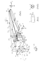
- the machine making it possible to cut the pile consists of a general frame 6 which comprises connecting means 7 with the three-point hitch system of a tractor not shown.
- This frame 6 comprises on the one hand, means for wedging the end of the pile 1 to be cut, and, on the other hand, means for guiding the knives 3 and 4 along lines parallel to the faces to be cut.
- the wedging means consist of a table 8 which is centered on the axis 5.
- the knives 3 are fixed in cantilever by heads 9, at the end of slides 10; these slides 10 are, in Figure 3, arranged in a horizontal plane passing through the axis 5 of the pile 1; they can be the same way in a vertical plane. These slides 10 converge at a point behind the table 8, on said axis 5. Each slide 10 is guided in a slide 11 which is connected to the frame 6.
- the slide 10 and the slide 11 have for example a square section which allows suitably guide the knives 3 while keeping them vertical and parallel to each other.
- the knives 4 are mounted in cantilever by heads 12, at the end of slides 13. These slides 13 are located in the same vertical plane, in FIG. 3, passing through the axis 5. This plane is perpendicular to the plane of the slides 10. The slides 13 also converge towards a point located on the axis 5, behind the table 8. The slides 13 are guided in slides 14 connected to the frame 6. Again the section slides 13 and slides 14 is preferably square to guide the knives 4 while keeping them parallel to each other and perpendicular to the edges of the knives 3.
- jacks 15 are maneuvered by means of jacks 15.
- a single jack 15 has been shown, in the foreground. This jack 15 is anchored on the slide 10 and on the rear end of the slide 11.
- the slides 13 are driven automatically by the slides 10, by means of connecting rods 16 interposed between the heads 9 and 12 which support the knives 3 and 4 respectively.
- the slide 11 is articulated at its rear end on the frame 6, around an axis 17 which is parallel to the edge of the knives 3.
- the front end of the slide 11 is guided in translation in a slide 18, between two arms which are perpendicular to the edge of the knives 3, to allow movement of said slide 11 in the horizontal plane.
- the slide 14 is articulated at its rear end, on the frame 6, by means of an axis 19 perpendicular to the axis 17.
- the front end of the slide 14 is guided in a slide 20, in arms perpendicular to those of the slide 18 to allow lateral movement in the vertical plane.
- Elastic return members in the form of springs 21 mounted on supports 21 'are interposed at the front end of the slides 11 and 14, between the latter and the frame 6. These springs 21 tend to hold the knives in an elastic manner 3 and 4 in their working position while allowing retraction in the event of obstacles or the like.
- the knives 3 constitute the first set which cuts two faces of the tip of the pile 1 and in particular, in FIG. 3, the two vertical faces
- This first set of knives 3 is arranged just in front of the second set of knives 4, which second game is responsible for cutting the other two faces of the tip of the pile 1.
- the knives 3 When the knives 3 arrive at the table 8, they move apart laterally and automatically, on either side of the table 8 to allow the jacks 15 to continue their strokes and to ensure the progress of the second set of knives 4 to table 8, in order to cut the other two faces of the tip of the pile 1.
- the slides 11, which are each mounted in the slides formed by the arms 18, automatically move apart by means of a ramp 22 arranged on the slides 10 at the level of the heads 9, which ramps 22 cooperate with rollers 23 integral with the frame 6, arranged in yokes 24. These rollers 23 are centered on parallel axes at the edges of the knives 3 and are located at the same level as the table 8, on either side of the latter.
- the ramps 22 come into contact with the rollers 23 just when the edges of the knives 3 arrive on the table 8.
- the movement of the slides 10 causes, due to the ramp 22, a movement of separation of the knives 3, laterally, guided in the slides 18.
- the knives 3 continue to run, on either side of the table 8, while the knives 4, positioned immediately behind, continue to cut the other two faces of the pile.
- FIG. 3 a cradle 25 which allows to guide the pile 1 and support it upstream of the knives.
- This cradle is articulated at the lower part of the head 12 of the knife 4, in FIG. 3.
- This cradle 25 is connected to the head 12 by means of a return spring 26; it retracts automatically when the knives come into action, while remaining in contact with the pile.
- a roller 27 disposed at its upper part, around a horizontal axis, facilitates the insertion of the pile and the guiding of its end to be cut up to the table 8.
- Knife operations are preferably controlled from a pedal 30 operated by the operator.
- This pedal 30 is associated with a limit switch 31 which is actuated by stops 32 and 33 arranged on one of the slides 10.
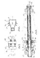
- Figure 4 in more detail, part of the frame 6 and the displacement means of one of the knives 3 which shape the vertical faces of the pile.
- the frame 6 comprises a central beam 35, of square section, centered on the axis 5. At the rear end of this beam 35, there are two pairs of yokes 36 and 37 which are used respectively for anchoring the slides 11 and 14 by means of axes 17 and 19. As indicated above, this anchoring can be of the multi-position type to allow variation of the angle of the tip of the pile.
- the front end of the beam 35 comprises a transverse plate 38 on which the table 8 and the slides 18 and 20 are fixed.
- the plate 38 also comprises the slides 18 and 20. These slides consist respectively of arms 41 and 42 arranged in horizontal and vertical planes. These arms 41 and 42 respectively enclose the slides 11 and 14 and allow movement of these slides in horizontal and vertical planes when in particular, the knives associated with these slides meet obstacles.
- the slides 11 and 14 are substantially identical in terms of their structure.
- the slide 11, shown in FIGS. 4 and 5, is made up of two plates 43 which enclose the slide 10. These plates 43 can be connected together by reinforcement strips arranged laterally. They are fixed to the frame 6 by means of the axis 17 and the yoke 36.
- rollers 44 at the front end of the plates 43, on the knife side, rollers 44, four in number in the figure, used for guide of the slide 10. These rollers are sandwiched between the two plates 43 and are guided on axes parallel to the axis 17. It is possible to provide additional rollers 44 ′ at the rear of the slides 11, 14 to improve the guide of the slides 10, 13, as shown in thin dashed lines, Figure 5.
- a cylinder 15, disposed directly in the slide 10, is anchored at its rear part on the axis 17 and, at its front part, by means of an axis 45, on said slide 10. This cylinder 15 causes a displacement of the slide 10 in the slide 11, with a guide in the rollers 44.
- the slider 10 retracts laterally, automatically, by means of the ramp 22 arranged at its end, and of the roller 23 which is secured to the frame 6 by means of a yoke 24.
- the ramp 22 as soon as it comes into contact with the roller 23, causes a lateral displacement of the blade 3 and moves it away from the table 8.
- the movement of the blade 3 continues towards the plate 38, so as to leave advancing the second set of blades 4 which ends the cutting of the tip of the pile 1.
- the advancement of the second set of blades 4 is effected by means of connecting rods 16 which join the heads 9 and 12 of the knives 3 and 4 respectively.
- FIG. 6 the shape of these heads 9 and 12.
- the head 9 is mounted at the end of the slide 10. It consists of two flat bars 46 which provide the connection between the blade 3 and the slide 10. These two flat irons 46 are spaced apart and in the form of a V from the slide 10. They thus allow the passage of the roller 23 and its support yoke 24 as well as the passage of the chips.
- the yokes 47 used for anchoring the connecting rods 16.
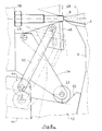
- FIG. 8 shows additional means which make it possible to substantially increase the surface of the table 8 to accommodate the end of the pile.
- These means consist of extensions 48 arranged on either side of the table 8, in the plane which includes the first set of knives 3.
- Each extension 48 is for example in the form of prism, one face of which serves as a table portion, and the top of which, at the end of the other two faces, is articulated on an axis 49. This axis 49 is parallel to the edge of the knives 3, arranged on the side of the table 8 so as to allow passage for said knives 3.
- extensions 48 are taken in a yoke in the supports 24 which support the rollers 23 serving to spread the slides 10.
- the extensions 48 are retractable by pivoting about the axes 49 under the effect of connecting rods 50 interposed between said extensions and the slides 11.
- These connecting rods 50 are for example articulated on the axis of the roller 44 which serves as a guide for the slide 10.
- FIG. 8 shows, in thin broken lines, the extension 48 in the retracted position, with the knife 3 interposed between said extension 48 and the table 8.
- This table 48 makes it possible to significantly increase the bearing surface of the end of the pile 1, when the maximum pressure is exerted due to the action of the knives. When the tables 48 retract, the cutting force is already greatly reduced.
- the frame 6 comprises a structure 51 which provides the connection between the central beam 35 and the members 7 used to hang the machine on the three-point hitch system of a tractor.
- This structure 51 also serves as a support for a hydraulic unit 52 which is connected to the power take-off of a tractor not shown; this central unit 52 serves to supply the actuating cylinders 15.
Abstract
Description
La présente invention concerne une machine pour appointer les pieux.The present invention relates to a machine for pointing piles.
L'opération qui consiste à tailler l'extrémité d'une pièce de bois pour pouvoir l'enfoncer dans le sol peut s'effectuer de différentes façons. Ces pieux ou piquets peuvent être taillés au moyen d'une sorte de taille-crayon pour réaliser une pointe conique. Ce type de taillage est assez pratique à réaliser mais il présente l'inconvénient de rendre moins efficace l'ancrage du pieu dans le sol.The operation of trimming the end of a piece of wood so that it can be pushed into the ground can be done in different ways. These stakes or stakes can be cut using a kind of pencil sharpener to make a conical point. This type of cutting is quite practical to carry out, but it has the disadvantage of making the anchoring of the stake in the ground less effective.
On préfère à la pointe conique, une pointe pyramidale, c'est-à-dire une pointe comportant quatre faces planes qui offrent une meilleure tenue du pieu dans le sol.We prefer to the conical point, a pyramidal point, that is to say a point comprising four flat faces which offer a better holding of the stake in the ground.
Des machines permettant d'appointer les pieux sont notamment décrites dans les documents EP-A-66368 et FR-A-2 440 257. Ces machines réalisent simplement le taillage d'une paire de faces opposées ; les deux autres faces sont taillées dans un deuxième temps, après pivotement du pieu d'un quart de tour.Machines for tacking the piles are described in particular in documents EP-A-66368 and FR-A-2 440 257. These machines simply cut a pair of opposite faces; the other two faces are cut in a second step, after the pile has been turned a quarter of a turn.
Cette opération de pivotement allonge le temps d'appointage d'un pieu ; elle présente surtout l'inconvénient de favoriser un défaut d'équerrage entre les deux couples de faces taillées.This pivoting operation lengthens the make-up time of a pile; it especially has the disadvantage of favoring a defect in squaring between the two pairs of cut faces.
La présente invention propose une machine qui présente l'avantage de tailler très rapidement un pieu et qui permet surtout de réaliser ce taillage avec une grande précision au niveau de l'équerrage des couples de faces taillées.The present invention provides a machine which has the advantage of cutting a pile very quickly and which above all allows this cutting to be carried out with great precision in terms of the squareness of the pairs of cut faces.
La machine selon l'invention comprend, d'une part, des couteaux qui sont mobiles selon des lignes passant par l'axe du pieu à tailler et convergentes sur ledit axe du pieu, et, d'autre part, un bâti qui rassemble :
- - une table servant d'appui pour l'extrémité du pieu à tailler,
- - des moyens de guidage desdits couteaux en forme de coulisses solidaires du bâti et de coulisseaux porteurs desdits couteaux ; cette machine comporte plus particulièrement, deux paires de couteaux décalées longitudinalement et disposées dans des plans perpendiculaires : - un premier jeu de couteaux étant mobile dans un premier plan, - un second jeu de couteaux étant mobile dans un second plan perpendiculaire au premier plan et agissant après le premier jeu pour finir de tailler la pointe.
- - a table serving as a support for the end of the pile to be cut,
- - Means for guiding said knives in the form of slides secured to the frame and of slides carrying said knives; this machine more particularly comprises two pairs of knives offset longitudinally and arranged in perpendicular planes: - a first set of knives being movable in a first plane, - a second set of knives being movable in a second plane perpendicular to the foreground and acting after the first game to finish carving the tip.
Cette disposition constructive procure un équerrage parfait des faces taillées et permet le taillage des quatre faces en une seule et même opération. Le premier plan, c'est-à-dire le plan dans lequel évolue le premier jeu de couteaux est soit horizontal, soit vertical. L'autre plan, c'est-à-dire le plan dans lequel évolue le second jeu, est, à l'inverse, soit vertical, soit horizontal.This constructive arrangement provides perfect squaring of the cut faces and allows the four faces to be cut in a single operation. The first plane, that is to say the plane in which the first set of knives evolves, is either horizontal or vertical. The other plane, that is to say the plane in which the second game evolves, is, conversely, either vertical or horizontal.
Selon une disposition préférentielle de l'invention, la machine comporte deux coulisseaux moteurs disposés dans un même plan, horizontal parexemple, manoeuvrés au moyen de vérins solidaires du bâti et deux coulisseaux disposés dans le plan vertical, manoeuvrés au moyen de bielles qui sont ancrées sur les coulisseaux moteurs. Toujours selon l'invention, les coulisses sont solidaires du bâti, à leur extrémité arrière, c'est-à-dire à l'opposé des couteaux, par l'intermédiaire d'un ancrage multi-positions, de façon à régler l'angle de taillage et l'épaisseur de la pointe du pieu ; cet ancrage comporte un axe parallèle à l'arête du couteau correspondant ; ces coulisses sont également guidées en translation, à l'autre extrémité, dans un plan perpendiculaire à ladite arête, passant par l'axe du pieu ; un organe de rappel élastique est interposé entre chaque coulisse et ledit bâti, pour maintenir le couteau correspondant sur sa ligne d'action.According to a preferred arrangement of the invention, the machine comprises two motor sliders arranged in the same plane, horizontal for example, maneuvered by means of jacks integral with the frame and two sliders arranged in the vertical plane, maneuvered by means of connecting rods which are anchored on the motor slides. Still according to the invention, the slides are integral with the frame, at their rear end, that is to say opposite the knives, by means of a multi-position anchoring, so as to adjust the cutting angle and thickness of the pile tip; this anchoring comprises an axis parallel to the edge of the corresponding knife; these slides are also guided in translation, at the other end, in a plane perpendicular to said edge, passing through the axis of the pile; an elastic return member is interposed between each slide and said frame, to maintain the corresponding knife on its line of action.
Selon une autre disposition essentielle de l'invention, la machine comporte des moyens d'escamotage du premier jeu de couteaux lorsque ces derniers atteignent la table ; ces moyens sont constitués d'un décrochement en forme de rampe, aménagé sur les coulisseaux portant lesdits couteaux, lequel décrochement coopère avec un guide en forme de rouleau solidaire du bâti, le forçant à s'écarter latéralement de la table.According to another essential arrangement of the invention, the machine comprises means for retracting the first set of knives when the latter reach the table; these means consist of a ramp-shaped recess, arranged on the slides carrying said knives, which recess cooperates with a roller-shaped guide secured to the frame, forcing it to move laterally from the table.
Toujours selon l'invention, des moyens du type contacteurs, disposés sur la coulisse, coopèrent avec au moins une butée disposée sur le coulisseau correspondant pour déclencher le retour des vérins de manoeuvre, lesquels moyens sont associés à une pédale de manoeuvre actionnée par l'opérateur.Still according to the invention, means of the contactor type, arranged on the slide, cooperate with at least one stop arranged on the corresponding slide to trigger the return of the actuating cylinders, which means are associated with an operating pedal actuated by the operator.
Selon une autre disposition de l'invention, les coulisses comportent au moins deux paires de rouleaux pour guider le coulisseau correspondant, et le vérin de manoeuvre est de préférence logé à l'intérieur du coulisseau, entre un axe solidaire de ce dernier disposé du côté des couteaux et l'axe d'articulation de la coulisse sur le bâti.According to another arrangement of the invention, the slides comprise at least two pairs of rollers to guide the corresponding slide, and the actuating cylinder is preferably housed inside the slide, between an axis integral with the latter arranged on the side knives and the axis of articulation of the slide on the frame.
Selon une autre disposition de l'invention, la table d'accueil de la pointe du pieu à tailler, comporte des rallonges disposées latéralement du côté du premier jeu de couteaux ; ces rallonges s'escamotent automatiquement, en même temps que le premier jeu de couteaux, dès qu'ils arrivent au niveau de ladite table.According to another arrangement of the invention, the reception table for the tip of the pile to be cut has extensions extended laterally on the side of the first set of knives; these extensions retract automatically, at the same time as the first set of knives, as soon as they reach the level of said table.
La machine selon l'invention comporte, de préférence, des moyens d'ancrage sur un système de relevage type trois points aménagé sur un tracteur ; elle comporte également une centrale hydraulique connectée à la prise de force dudit tracteur, pour réaliser l'alimentation des organes de manoeuvre des couteaux.The machine according to the invention preferably comprises anchoring means on a three-point type lifting system fitted on a tractor; it also includes a hydraulic unit connected to the power take-off of said tractor, for supplying the knife operating members.
L'invention sera encore détaillée à l'aide de la description suivante d'un mode de réalisation, et des dessins annexés, donnés à titre indicatif, et dans lesquels :
- - les figures 1 et 2 représentent l'extrémité d'un pieu à pointe pyramidale, vu de côté et vu en bout, respectivement ;
- - la figure 3 illustre, au moyen d'un schéma fonctionnel, la machine à appointer selon l'invention ;
- - la figure 4 représente, de façon partielle, vus de dessus, le bâti et la coulisse et coulisseau de l'un des couteaux moteurs ;
- - la figure 5 est une vue en coupe de la figure 4, selon 5-5 ;
- - la figure 6 est une vue en coupe de la figure 4, selon 6-6 ;
- - la figure 7 est une vue en coupe de la figure 4, selon 7-7.
- - la figure 8 représente un système de rallonges, lesquelles sont disposées de part et d'autre de la table d'accueil de la pointe à tailler.
- - Figures 1 and 2 show the end of a pile with pyramidal point, seen from the side and seen from the end, respectively;
- - Figure 3 illustrates, by means of a functional diagram, the punching machine according to the invention;
- - Figure 4 shows, partially, seen from above, the frame and the slide and slide of one of the motor knives;
- - Figure 5 is a sectional view of Figure 4, along 5-5;
- - Figure 6 is a sectional view of Figure 4, along 6-6;
- - Figure 7 is a sectional view of Figure 4, along 7-7.
- - Figure 8 shows a system of extensions, which are arranged on either side of the reception table of the tip to be cut.
On a représenté, figures 1 et 2, l'extrémité d'un pieu 1 dont la pointe est taillée conformément à l'invention, selon une pyramide avec quatre faces 2 parfaitement planes offrant une bonne résistance dans le sol. Deux faces opposées font entre elles un angle de l'ordre de 20°.There is shown, Figures 1 and 2, the end of a pile 1 whose tip is cut according to the invention, according to a pyramid with four perfectly flat faces 2 offering good resistance in the ground. Two opposite faces form an angle of about 20 ° between them.
Pour réaliser ces quatre faces, on utilise, comme représenté figure 3, deux paires de couteaux 3 et 4 ; le couple de couteaux 3 est décalé longitudinalement par rapport au couple de couteaux 4, et il est situé en avant pour agir en premier. La distance qui sépare longitudinalement les deux jeux de couteaux 3 et 4 est relativement réduite de façon à faire agir simultanément lesdits jeux pendant une partie du taillage, pour obtenir un parfait équerrage des faces 2 constituant la pointe du pieu. Ces couteaux se présentent sous la forme de lames. Les lames des couteaux 3 sont verticales alors que les lames des couteaux 4 sont horizontales ; elles comportent une légère dépouille de façon classique.To make these four faces, as shown in FIG. 3, two pairs of
Le couple de couteaux 3 se déplace dans un plan horizontal situé sur l'axe 5 qui correspond à l'axe général de la machine et à celui du pieu 1. Dans ce plan horizontal, chaque lame des couteaux 3 se déplace selon des lignes qui convergent vers cet axe 5 ; l'angle entre ces lignes est de l'ordre de 20°.The pair of
Le couple de couteaux 4 se déplace dans un plan vertical qui passe lui aussi par l'axe 5 et les lignes de mouvement de ces couteaux 4 convergent elles aussi vers l'axe 5.The pair of
La machine permettant de réaliser le taillage du pieu est constituée d'un bâti général 6 qui comporte des moyens de liaison 7 avec le système d'attelage trois points d'un tracteur non représenté. Ce bâti 6 comprend d'une part, des moyens de calage de l'extrémité du pieu 1 à tailler, et, d'autre part, des moyens de guidage des couteaux 3 et 4 selon des lignes parallèles aux faces à tailler. Les moyens de calage sont constitués d'une table 8 qui est centrée sur l'axe 5.The machine making it possible to cut the pile consists of a
Les couteaux 3 sont fixés en porte-à-faux par des têtes 9, à l'extrémité de coulisseaux 10 ; ces coulisseaux 10 sont, sur la figure 3, disposés dans un plan horizontal passant par l'axe 5 du pieu 1 ; ils peuvent être de la même façon dans un plan vertical. Ces coulisseaux 10 convergent en un point situé derrière la table 8, sur ledit axe 5. Chaque coulisseau 10 est guidé dans une coulisse 11 qui est reliée au bâti 6. Le coulisseau 10 et la coulisse 11 ont par exemple une section carrée qui permet de guider convenablement les couteaux 3 en les maintenant verticaux et parallèles l'un par rapport à l'autre.The
De la même façon, les couteaux 4 sont montés en porte-à-faux par des têtes 12, à l'extrémité de coulisseaux 13. Ces coulisseaux 13 sont situés dans un même plan vertical, sur la figure 3, passant par l'axe 5. Ce plan est perpendiculaire au plan des coulisseaux 10. Les coulisseaux 13 convergent également vers un point situé sur l'axe 5, derrière la table 8. Les coulisseaux 13 sont guidés dans des coulisses 14 reliées au bâti 6. Là aussi la section des coulisseaux 13 et des coulisses 14 est de préférence carrée pour réaliser un guidage des couteaux 4 en les maintenant parallèles entre eux et perpendiculaires aux arêtes des couteaux 3.In the same way, the
On remarque que les coulisseaux 10 sont manoeuvrés au moyen de vérins 15. Pour simplifier la figure, un seul vérin 15 a été représenté, en premier plan. Ce vérin 15 est ancré sur le coulisseau 10 et sur l'extrémité arrière de la coulisse 11.It is noted that the
Les coulisseaux 13 sont entraînés automatiquement par les coulisseaux 10, au moyen de bielles 16 interposées entre les têtes 9 et 12 qui supportent respectivement les couteaux 3 et 4.The
On remarque, figure 3 et de façon plus précise figures 4 et 5, que les coulisses 11 et 14 sont mobiles par rapport au bâti. Ces coulisses ont en particulier la faculté de s'écarter latéralement dans leur plan respectif c'est-à-dire horizontal pour les coulisses 11 et vertical pour les coulisses 14, de façon à sauter un obstacle automatiquement sur le pieu par exemple ou, comme détaillé ci-après, pour s'écarter de la table 8.Note, Figure 3 and more precisely Figures 4 and 5, that the
La coulisse 11 est articulée à son extrémité arrière sur le bâti 6, autour d'un axe 17 qui est parallèle à l'arête des couteaux 3. L'extrémité avant de la coulisse 11 est guidée en translation dans une glissière 18, entre deux bras qui sont perpendiculaires à l'arête des couteaux 3, pour permettre le mouvement de ladite coulisse 11 dans le plan horizontal. De la même façon, la coulisse 14 est articulée à son extrémité arrière, sur le bâti 6, au moyen d'un axe 19 perpendiculaire à l'axe 17. L'extrémité avant de la coulisse 14 est guidée dans une glissière 20, dans des bras perpendiculaires à ceux de la glissière 18 pour permettre le déplacement latéral dans le plan vertical.The
Pour faire varier l'angle de taillage des pieux, on peut prévoir un ancrage multi-positions des coulisseaux 11 et 13 sur le bâti 6, au niveau des axes 17 et 19 respectivement. Ce réglage permet également d'affiner plus ou moins la pointe du pieu.To vary the cutting angle of the piles, it is possible to provide a multi-position anchoring of the
Des organes de rappel élastique en forme de ressorts 21 montés sur des supports 21' sont interposés à l'extrémité avant des coulisses 11 et 14, entre ces dernières et le bâti 6. Ces ressorts 21 tendent à maintenir, de façon élastique, les couteaux 3 et 4 dans leur position de travail tout en permettant un escamotage en cas de rencontre d'obstacles ou autres.Elastic return members in the form of
Les couteaux 3 constituent le premier jeu qui taille deux faces de la pointe du pieu 1 et en particulier, sur la figure 3, les deux faces verticales Ce premier jeu de couteaux 3 est disposé juste en avant du second jeu de couteaux 4, lequel second jeu est chargé de tailler les deux autres faces de la pointe du pieu 1.The
Lorsque les couteaux 3 arrivent au niveau de la table 8, ils s'écartent latéralement et automatiquement, de part et d'autre de la table 8 pour permettre aux vérins 15 de poursuivre leurs courses et d'assurer la progression du second jeu de couteaux 4 jusqu'à la table 8, afin de tailler les deux autres faces de la pointe du pieu 1. Pour réaliser cet escamotage du premier jeu de couteaux 3, les coulisses 11, qui sont montées chacune dans les glissières formées par les bras 18, s'écartent automatiquement au moyen d'une rampe 22 aménagée sur les coulisseaux 10 au niveau des têtes 9, lesquelles rampes 22 coopèrent avec des galets 23 solidaires du bâti 6, disposés dans des chapes 24. Ces galets 23 sont centrés sur des axes parallèles aux arêtes des couteaux 3 et se situent au même niveau que la table 8, de part et d'autre de cette dernière. Les rampes 22 entrent en contact avec les rouleaux 23 juste au moment où les arêtes des couteaux 3 arrivent sur la table 8. Le mouvement des coulisseaux 10 provoque, du fait de la rampe 22, un mouvement d'écartement des couteaux 3, latéralement, guidés dans les glissières 18.When the
Les couteaux 3 poursuivent leur course, de part et d'autre de la table 8, pendant que les couteaux 4, positionnés immédiatement derrière, continuent à tailler les deux autres faces du pieu.The
On remarque, figure 3, un berceau 25 qui permet de guider le pieu 1 et de le soutenir en amont des couteaux. Ce berceau est articulé à la partie inférieure de la tête 12 du couteau 4, sur la figure 3. Ce berceau 25 est relié à la tête 12 au moyen d'un ressort de rappel 26 ; il s'escamote automatiquement lorsque les couteaux entrent en action, tout en restant en contact avec le pieu. Un rouleau 27 disposé à sa partie supérieure, autour d'un axe horizontal, facilite l'introduction du pieu et le guidage de son extrémité à taillerjus- que sur la table 8.Note, Figure 3, a
Les manoeuvres des couteaux sont de préférence commandées à partir d'une pédale 30 manoeuvrée par l'opérateur. Cette pédale 30 est associée à un contacteur 31 de fin de course qui est actionné par des butées 32 et 33 disposées sur l'un des coulisseaux 10.Knife operations are preferably controlled from a pedal 30 operated by the operator. This
On a représenté, figure 4, de façon plus détaillée, une partie du bâti 6 et les moyens de déplacement de l'un des couteaux 3 qui façonnent les faces verticales du pieu.There is shown, Figure 4, in more detail, part of the
Le bâti 6 comporte une poutre centrale 35, de section carrée, centrée sur l'axe 5. A l'extrémité arrière de cette poutre 35, on trouve deux paires de chapes 36 et 37 qui servent respectivement à l'ancrage des coulisses 11 et 14 au moyen des axes 17 et 19. Comme indiqué précédemment, cet ancrage peut être du type multi-positions pour permettre une variation de l'angle de la pointe du pieu. L'extrémité avant de la poutre 35 comprend une platine transversale 38 sur laquelle sont fixées la table 8 et les glissières 18 et 20.The
On remarque, figure 7, la platine 38 solidaire de l'extrémité de la poutre 35. Cette platine 38 est traversée par des goujons 39 disposés de part et d'autre de la poutre 35, dans un plan vertical ; ces goujons 39 sont solidaires de la table 8 et permettent le réglage de cette dernière par rapport à la platine 38. On remarque encore, figure 7, que la table 8 est guidée à ses extrémités supérieure et inférieure entre des plateaux 40.Note, in Figure 7, the
La platine 38 comporte également les glissières 18 et 20. Ces glissières sont respectivement constituées de bras 41 et 42 disposés dans des plans horizontaux et verticaux. Ces bras 41 et 42 enserrent respectivement les coulisses 11 et 14 et permettent un mouvement de ces coulisses dans des plans horizontaux et verticaux lorsque notamment, les couteaux associés à ces coulisses rencontrent des obstacles.The
Les coulisses 11 et 14 sont sensiblement identiques au niveau de leur structure. La coulisse 11, représentée figures 4 et 5, est constituée de deux plaques 43 qui enserrent le coulisseau 10. Ces plaques 43 peuvent être reliées entre elles par des bandes de renforcement disposées latéralement. Elles sont fixées au bâti 6 au moyen de l'axe 17 et de la chape 36. On remarque, à l'extrémité avant des plaques 43, du côté des couteaux, des rouleaux 44, au nombre de quatre sur la figure, servant au guidage du coulisseau 10. Ces rouleaux sont enserrés entre les deux plaques 43 et sont guidés sur des axes parallèles à l'axe 17. On peut prévoir des rouleaux complémentaires 44' à la partie arrière des coulisses 11, 14 pour améliorer le guidage des coulisseaux 10, 13, comme représentés en traits mixtes fins, figure 5.The
En avant des bras 41, on remarque, figure 4, le ressort de rappel 21 interposé entre la coulisse 11 et une patte 21' montée sur la chape 24 qui est solidaire de la platine 38 et qui soutient le galet 23.In front of the
Un vérin 15, disposé directement dans le coulisseau 10, est ancré à sa partie arrière sur l'axe 17 et, à sa partie avant, au moyen d'un axe 45, sur ledit coulisseau 10. Ce vérin 15 provoque un déplacement du coulisseau 10 dans la coulisse 11, avec un guidage dans les rouleaux 44.A
Lorsque le couteau 3 arrive au niveau de la table 8, le coulisseau 10 s'escamote latéralement, automatiquement, au moyen de la rampe 22 aménagée à son extrémité, et du rouleau 23 qui est solidaire du bâti 6 au moyen d'une chape 24.When the
La rampe 22, dès qu'elle entre en contact avec le rouleau 23, provoque un déplacement latéral de la lame 3 et l'écarte de la table 8. Le mouvement de la lame 3 se poursuit vers la platine 38, de façon à laisser avancer le second jeu de lames 4 qui termine le taillage de la pointe du pieu 1. L'avancement du second jeu de lames 4 s'effectue au moyen des bielles 16 qui joignent les têtes 9 et 12 des couteaux 3 et 4 respectivement.The
On remarque, figure 6, la forme de ces têtes 9 et 12. La tête 9 est montée à l'extrémité du coulisseau 10. Elle est constituée de deux fers plats 46 qui assurent la liaison entre la lame 3 et le coulisseau 10. Ces deux fers plats 46 sont écartés et en forme de V à partir du coulisseau 10. Ils permettent ainsi le passage du galet 23 et de sa chape support 24 ainsi que le passage des copeaux. On remarque, solidaires des fers plats 46, les chapes 47 servant à l'ancrage des bielles 16.Note, Figure 6, the shape of these
On a représenté, figure 8, des moyens complémentaires qui permettent d'augmenter sensiblement la surface de la table 8 pour accueillir l'extrémité du pieu. Ces moyens, qui apparaissent figure 3 en traits mixtes fins, consistent en des rallonges 48 disposées de part et d'autre de la table 8, dans le plan qui comprend le premier jeu de couteaux 3. Chaque rallonge 48 est par exemple en forme de prisme dont une face sert de portion de table, et dont le sommet, à l'extrémité des deux autres faces, est articulé sur un axe 49. Cet axe 49 est parallèle à l'arête des couteaux 3, disposé sur le côté de la table 8 de façon à laisser le passage auxdits couteaux 3.FIG. 8 shows additional means which make it possible to substantially increase the surface of the table 8 to accommodate the end of the pile. These means, which appear in Figure 3 in thin dashed lines, consist of
En fait, les rallonges 48 sont prises en chape dans les supports 24 qui soutiennent les galets 23 servant à écarter les coulisseaux 10.In fact, the
Les rallonges 48 sont escamotables en pivotant autour des axes 49 sous l'effet de bielles 50 interposées entre lesdites rallonges et les coulisses 11. Ces bielles 50 sont par exemple articulées sur l'axe du galet 44 qui sert de guide au coulisseau 10. On a représenté, figure 8, en traits mixtes fins, la rallonge 48 en position escamotée, avec le couteau 3 interposé entre ladite rallonge 48 et la table 8.The
Cette table 48 permet d'augmenter sensiblement la surface d'appui de l'extrémité du pieu 1, au moment où s'exerce le maximum de pression du fait de l'action des couteaux. Lorsque les tables 48 s'escamotent, l'effort de coupe est déjà fortement réduit.This table 48 makes it possible to significantly increase the bearing surface of the end of the pile 1, when the maximum pressure is exerted due to the action of the knives. When the tables 48 retract, the cutting force is already greatly reduced.
On remarque encore, figure 4, que le bâti 6 comprend une structure 51 qui assure la liaison entre la poutre centrale 35 et les organes 7 servant à accrocher la machine sur le système d'attelage trois points d'un tracteur. Cette structure 51 sert également de support à une centrale hydraulique 52 qui est réliée à la prise de force d'untracteur non représenté ; cette centrale 52 sert à l'alimentation des vérins 15 de manoeuvre.Note also, in Figure 4, that the
Les signes de référence insérés après les caractéristiques techniques mentionnées dans les revendications ont pour seul but de faciliter la compréhension de ces dernières et n'en limitent aucunement la portée.The reference signs inserted after the technical characteristics mentioned in the claims have the sole purpose of facilitating the understanding of the latter and in no way limit their scope.
Claims (10)
Applications Claiming Priority (2)
| Application Number | Priority Date | Filing Date | Title |
|---|---|---|---|
| FR9115837A FR2684914B1 (en) | 1991-12-17 | 1991-12-17 | MACHINE FOR ADDING THE PILES. |
| FR9115837 | 1991-12-17 |
Publications (1)
| Publication Number | Publication Date |
|---|---|
| EP0547962A1 true EP0547962A1 (en) | 1993-06-23 |
Family
ID=9420259
Family Applications (1)
| Application Number | Title | Priority Date | Filing Date |
|---|---|---|---|
| EP92403419A Withdrawn EP0547962A1 (en) | 1991-12-17 | 1992-12-15 | Machine for pile-pointing |
Country Status (3)
| Country | Link |
|---|---|
| EP (1) | EP0547962A1 (en) |
| CA (1) | CA2085305A1 (en) |
| FR (1) | FR2684914B1 (en) |
Cited By (3)
| Publication number | Priority date | Publication date | Assignee | Title |
|---|---|---|---|---|
| EP0988817A1 (en) * | 1998-09-24 | 2000-03-29 | Michael Dickhut | Method and device for erecting rod-like devices, in particular Christmas trees |
| FR2955285A1 (en) * | 2009-12-09 | 2011-07-22 | Jean Noel Merle | Device for sharpening three or four faces of wooden piece, has supply opening for supplying pieces of wood arranged in inlet plate, and guiding unit for guiding cutting unit between inlet and outlet plates |
| CN111438773A (en) * | 2020-04-03 | 2020-07-24 | 于云仙 | Gardens are with stake device of sharpening |
Citations (3)
| Publication number | Priority date | Publication date | Assignee | Title |
|---|---|---|---|---|
| FR2440257A1 (en) * | 1978-11-03 | 1980-05-30 | Lefort Marcel | Wooden post pointing cutter - has two knives in vertical planes with adjustable angle between |
| EP0066368A1 (en) * | 1981-05-19 | 1982-12-08 | Hydrocut Limited | Apparatus for cutting a workpiece |
| US4875514A (en) * | 1988-10-24 | 1989-10-24 | Hollister Jr Graham | Wood splitting method and apparatus |
-
1991
- 1991-12-17 FR FR9115837A patent/FR2684914B1/en not_active Expired - Fee Related
-
1992
- 1992-12-14 CA CA 2085305 patent/CA2085305A1/en not_active Abandoned
- 1992-12-15 EP EP92403419A patent/EP0547962A1/en not_active Withdrawn
Patent Citations (3)
| Publication number | Priority date | Publication date | Assignee | Title |
|---|---|---|---|---|
| FR2440257A1 (en) * | 1978-11-03 | 1980-05-30 | Lefort Marcel | Wooden post pointing cutter - has two knives in vertical planes with adjustable angle between |
| EP0066368A1 (en) * | 1981-05-19 | 1982-12-08 | Hydrocut Limited | Apparatus for cutting a workpiece |
| US4875514A (en) * | 1988-10-24 | 1989-10-24 | Hollister Jr Graham | Wood splitting method and apparatus |
Cited By (3)
| Publication number | Priority date | Publication date | Assignee | Title |
|---|---|---|---|---|
| EP0988817A1 (en) * | 1998-09-24 | 2000-03-29 | Michael Dickhut | Method and device for erecting rod-like devices, in particular Christmas trees |
| FR2955285A1 (en) * | 2009-12-09 | 2011-07-22 | Jean Noel Merle | Device for sharpening three or four faces of wooden piece, has supply opening for supplying pieces of wood arranged in inlet plate, and guiding unit for guiding cutting unit between inlet and outlet plates |
| CN111438773A (en) * | 2020-04-03 | 2020-07-24 | 于云仙 | Gardens are with stake device of sharpening |
Also Published As
| Publication number | Publication date |
|---|---|
| FR2684914B1 (en) | 1995-06-09 |
| CA2085305A1 (en) | 1993-06-18 |
| FR2684914A1 (en) | 1993-06-18 |
Similar Documents
| Publication | Publication Date | Title |
|---|---|---|
| FR2955047A3 (en) | ||
| CH640694A5 (en) | DEVICE FOR CUTTING GRASS UNDER BARRIERS. | |
| EP0547962A1 (en) | Machine for pile-pointing | |
| FR2630286A1 (en) | Implement with discs for working the ground at a depth | |
| CA2724925C (en) | Retractable and automatic positioning wheels for snowmobiles | |
| EP0236162B1 (en) | Grafting machine | |
| EP0018868A1 (en) | Machine for longitudinally splitting slabs by flame cutting | |
| EP1212932B1 (en) | Seeder | |
| FR3062986A1 (en) | RACING DEVICE WITH LEATABLE SIDE RACING ARRANGEMENTS | |
| FR2948850A1 (en) | Plant cutting/crushing equipment for use in towing vehicle, has radial notches receiving obstacle e.g. tree trunks, during advancement of towing vehicle causing rotation of cutting/crushing head to circumvent obstacle | |
| EP0611519B1 (en) | Transplanter for seedling blocks | |
| FR2627761A1 (en) | Flat plate transfer transformer - has scissors jack carrying chassis with suction plate and plate alignment stops | |
| EP2179640A1 (en) | Machine for cutting plants | |
| EP1021942B1 (en) | Agricultural Harrow | |
| FR2676324A1 (en) | Improved spade | |
| FR2602631A1 (en) | Plough with symmetrical bases | |
| EP0777959A1 (en) | Lawn border cutter | |
| WO2005015974A2 (en) | Forest soil treating combine | |
| FR2800972A1 (en) | Apparatus, for reaping vegetables, comprises first and second frames, with profile of first frame attached to profile of second frame using links | |
| EP1026936B1 (en) | Method for sheathing bales of plants and equipment for implementing same | |
| BE542842A (en) | ||
| FR3139973A1 (en) | AGRICULTURAL MACHINE COMPRISING AN ARCH AND A PARTICULAR FIXING SYSTEM FIXED TO THE ARCH AND PROVIDING THE FIXATION OF A TOOL | |
| FR2517504A1 (en) | ||
| EP0420971A1 (en) | Plough with symmetrical body, with adjustable variable angle of attack and variable working width | |
| BE481968A (en) |
Legal Events
| Date | Code | Title | Description |
|---|---|---|---|
| PUAI | Public reference made under article 153(3) epc to a published international application that has entered the european phase |
Free format text: ORIGINAL CODE: 0009012 |
|
| AK | Designated contracting states |
Kind code of ref document: A1 Designated state(s): BE CH DE ES GB IE IT LI |
|
| 17P | Request for examination filed |
Effective date: 19931027 |
|
| 17Q | First examination report despatched |
Effective date: 19941129 |
|
| STAA | Information on the status of an ep patent application or granted ep patent |
Free format text: STATUS: THE APPLICATION IS DEEMED TO BE WITHDRAWN |
|
| 18D | Application deemed to be withdrawn |
Effective date: 19950711 |