EP0545899A2 - Sliding bar lock - Google Patents
Sliding bar lock Download PDFInfo
- Publication number
- EP0545899A2 EP0545899A2 EP93101846A EP93101846A EP0545899A2 EP 0545899 A2 EP0545899 A2 EP 0545899A2 EP 93101846 A EP93101846 A EP 93101846A EP 93101846 A EP93101846 A EP 93101846A EP 0545899 A2 EP0545899 A2 EP 0545899A2
- Authority
- EP
- European Patent Office
- Prior art keywords
- drive rod
- der
- lock
- bolt
- cam
- Prior art date
- Legal status (The legal status is an assumption and is not a legal conclusion. Google has not performed a legal analysis and makes no representation as to the accuracy of the status listed.)
- Granted
Links
Images


Classifications
-
- E—FIXED CONSTRUCTIONS
- E05—LOCKS; KEYS; WINDOW OR DOOR FITTINGS; SAFES
- E05C—BOLTS OR FASTENING DEVICES FOR WINGS, SPECIALLY FOR DOORS OR WINDOWS
- E05C9/00—Arrangements of simultaneously actuated bolts or other securing devices at well-separated positions on the same wing
- E05C9/02—Arrangements of simultaneously actuated bolts or other securing devices at well-separated positions on the same wing with one sliding bar for fastening when moved in one direction and unfastening when moved in opposite direction; with two sliding bars moved in the same direction when fastening or unfastening
- E05C9/021—Arrangements of simultaneously actuated bolts or other securing devices at well-separated positions on the same wing with one sliding bar for fastening when moved in one direction and unfastening when moved in opposite direction; with two sliding bars moved in the same direction when fastening or unfastening with rack and pinion mechanism
- E05C9/023—Arrangements of simultaneously actuated bolts or other securing devices at well-separated positions on the same wing with one sliding bar for fastening when moved in one direction and unfastening when moved in opposite direction; with two sliding bars moved in the same direction when fastening or unfastening with rack and pinion mechanism between a lock cylinder and the bar
-
- E—FIXED CONSTRUCTIONS
- E05—LOCKS; KEYS; WINDOW OR DOOR FITTINGS; SAFES
- E05B—LOCKS; ACCESSORIES THEREFOR; HANDCUFFS
- E05B15/00—Other details of locks; Parts for engagement by bolts of fastening devices
- E05B15/004—Lost motion connections
-
- E—FIXED CONSTRUCTIONS
- E05—LOCKS; KEYS; WINDOW OR DOOR FITTINGS; SAFES
- E05B—LOCKS; ACCESSORIES THEREFOR; HANDCUFFS
- E05B17/00—Accessories in connection with locks
- E05B17/20—Means independent of the locking mechanism for preventing unauthorised opening, e.g. for securing the bolt in the fastening position
- E05B17/2007—Securing, deadlocking or "dogging" the bolt in the fastening position
- E05B17/203—Securing, deadlocking or "dogging" the bolt in the fastening position not following the movement of the bolt
- E05B17/2034—Securing, deadlocking or "dogging" the bolt in the fastening position not following the movement of the bolt moving pivotally or rotatively
-
- E—FIXED CONSTRUCTIONS
- E05—LOCKS; KEYS; WINDOW OR DOOR FITTINGS; SAFES
- E05C—BOLTS OR FASTENING DEVICES FOR WINGS, SPECIALLY FOR DOORS OR WINDOWS
- E05C9/00—Arrangements of simultaneously actuated bolts or other securing devices at well-separated positions on the same wing
- E05C9/18—Details of fastening means or of fixed retaining means for the ends of bars
- E05C9/1825—Fastening means
- E05C9/1875—Fastening means performing pivoting movements
Definitions
- the invention relates to a connecting rod lock comprising a connecting rod which can be displaced between an open position and a closed position in connection with at least one closing element.
- a lock cylinder a reduction gear between the lock cylinder and the drive rod for moving the drive rod between the open position and the closed position and a locking device for the drive rod, which locks the drive rod in the closed position against displacement in the direction of the open position without introducing torque into the reduction gear
- a control cam assembly for drive engagement in a cam engagement profiling of the drive rod on a transmission output drive rod drive pinion is appropriate and wherein, furthermore, a stop cam for engaging on an abutment surface of the drive rod is attached to the drive rod drive pinion on the transmission output side.
- a single control cam is attached to the drive rod drive pinion, which is in drive engagement with the drive rod for a single recess in the drive rod.
- a stop cam is attached to the drive rod drive pinion, which comes into engagement in a further recess of the drive rod when the drive rod is in its open position, so that the drive rod, which is in the open position and loads towards its closed position is supported exclusively via the stop cam in the recess of the drive rod associated therewith, without substantial supporting forces being introduced into the reduction gear.
- the locking cylinder is rotated 2 ⁇ 360 °, starting from a zero or key withdrawal position of the locking cylinder.
- the locking cylinder is rotated further by 360 o ; during this further rotation by a further 360 ° , the stop cam then comes into the recess in the drive rod provided for it with the drive rod at a standstill.
- the invention has for its object to provide a drive rod lock of the type mentioned a structurally simpler or at least consistently simple construction that allows the transition from the open position of the drive rod to the blocking of the drive rod in the closed position with a lower number of revolutions on the lock cylinder to be able to perform.
- the espagnolette starting from the open position and accordingly from a zero position (key withdrawal position) of the lock cylinder, reaches its lock position after less than 2 x 360 o lock cylinder rotation, and that the remaining lock cylinder rotation corresponds to the rest up to 2 x 360 o serves to retract the stop cam in the locking position opposite the locking flank of the limiting finger.
- the drive rod drive pinion o a closing rotating movement of about 200 performs o during a closing rotating movement of the lock cylinder of 2 x 360th
- This closing rotational movement of the drive rod drive pinion is used, on the one hand, to shift the drive rod from the open position into the closed position and, on the other hand, to lock the drive rod in the closed position in that the stop cam runs onto the locking flank of the limiting finger.
- the remaining closing rotational movement of the drive rod drive pinion after the drive rod has entered the closed position must be small, for example approximately 20 ° .
- control cams and the stop cams can project axially with respect to a simple construction from an end face of the drive rod drive pinion, in which case a part of the drive rod carrying the recesses can rest against this end face of the drive rod drive pinion.
- control cams are connected to one another by a web while maintaining a recess between them for the engagement of a projection lying between the two recesses.
- the espagnolette lock according to the invention can be produced in particular in the form that a transom movable to the direction of movement of the espagnolette or Main bolt is provided and is displaceable between a retracted position and an extended position by the drive rod.
- the bolt can be driven from the drive rod in such a way that a stationary angular lever is connected to a first arm by a pin-slot connection to a bolt tail of the bolt, and that a second arm of the angle lever , namely a control arm with a control profile of the drive rod is engaged.
- the control profile can have control surfaces at right angles to the direction of movement of the bolt for extending and retracting the bolt and an end surface which is essentially parallel to the direction of movement of the drive rod for locking the extended bolt.
- Additional locking of the extended latch can be accomplished by attaching a shoulder to the latch and a shoulder engaging pin on the drive rod, the shoulder engaging pin engaging behind the shoulder after the latch has reached its fully extended position. Due to the simultaneous engagement of the control arm with the end face of the control profile on the one hand and the shoulder with the shoulder engagement pin on the other hand, an extremely stable blocking against a violent pushing in of the bolt is achieved, the supporting forces being distributed within the lock in such a way that there is no fear of damage to the furnishings is.
- the espagnolette lock can also be equipped with at least one pivot bolt which can be pivoted between a pivoted-in and a pivoted-out position by the drive rod.
- a toothed rack can be attached to the drive rod for pivoting the swivel bolt, and accordingly a toothed segment can be attached to the swivel bolt.
- This toothed segment can be attached to a hub part of the hook-shaped swivel bolt.
- the swivel bolt itself can be part of an additional lock attached to a faceplate of the lock.
- the lock designed according to the invention can further be equipped with a latch which, in a known manner, automatically engages in a striking plate when the door equipped with the lock slams shut.
- This case is biased in a conventional manner under spring pressure into a closed position and can be pulled back into an open position either by turning a follower nut or from the lock cylinder.
- a driver can be attached to the drive rod drive pinion, which, when the locking cylinder is rotated, strikes beyond its zero position corresponding to the open position of the drive rod, against a nose of a drop lever acting on the latch.
- the latch can basically be of the usual prismatic design, that is to say that the latch in a sectional plane perpendicular to the door lock plane and parallel to the direction of movement of the latch has a triangular cross-section with a latch start slope and a latch latch flank, and furthermore that the latch is essentially parallel to this sectional plane having.
- the recesses on the trap can in particular be designed as grooves which run parallel to the outer surface of the faceplate and, in the presence of trap guide ribs running along the latch latch flank and along the end surfaces of the trap, end in front of or on these trap guide ribs.
- the trap guide ribs thus remain intact and there is no danger that they will get caught in the guides of the cuff when the trap is pulled back.
- the starting point is a connecting rod lock comprising a connecting rod which can be displaced between an open position and a closed position in connection with at least one closing element, a lock cylinder, a reduction gear between the lock cylinder and the drive rod for moving the drive rod between the open position and the closed position, wherein the reduction gear on the lock cylinder side has a toothed ring which meshes with two output gears arranged downstream of it and has a slot designed to insert the locking bar of the lock cylinder and is open towards the edge, and wherein a drive rod drive member of the reduction gear rotatable about a fixed axis acts on the drive rod via a driving device , further comprehensive a bolt which can be moved transversely to the longitudinal axis of the drive rod between a retracted position and an extended position and can be driven from the drive rod by means of movement conversion means, more comprehensive a case biased by spring force into a closed position, which can be retracted against the spring force from a follower and from the lock cylinder
- Such a drive rod lap is known from DE-PS 29 19 201.
- the adjustment of the slide bolt is when pivoting of the slot of the ring gear from its zero degree position by the variation angle range of the locking bar enables that the movement conversion means between the bolt and the drive rod are formed by an oblique slot of the drive rod and a slot follower bolt of the slide bolt and that the oblique slot of the drive rod by a extending in the direction of movement of the drive rod Niche is added, in which the pin of the slide bolt has entered in the closed end position of the slide bolt, and has axial play.
- the trap is driven by the drive rod.
- the drive rod is moved from the locking cylinder and takes the trap back with it, the slide bolt standing still in the niche thanks to the play of its pin.
- This embodiment is burdened with considerable disadvantages: to retract the trap, the drive rod must always be moved. This means additional effort and additional wear and tear in the espagnolette lock and requires additional adjustment of the frame-side locking plates in order to grant the espagnolette-side locking elements a corresponding movement play during the espagnolette movement necessary for the latch retraction.
- the invention has for its object to find a solution while maintaining the variation angle range for the lock cylinder bit and while maintaining the immobility of the slide bolt when adjusting the lock cylinder bar within this variation angle range, in which effects on the drive rod in the open position do not lead to the lock cylinder load and the drive rod when Retrieving the latch from the lock cylinder stands still.
- a cam assembly attached to the drive rod drive member with two control cams and a stop cam and a cam engagement profile attached to the drive rod with two recesses associated with the control cams and two limiting fingers be formed on both sides of the recesses in such a way that when the toothed ring is rotated within the variation angle range of the locking bar, the driving connection of the control cam responsible for the start of the drive rod displacement from the open position into the closed position with the associated recess is released and the limiting finger associated with this recess interferes with the displacement of the drive rod between the stop cams and the axis of the drive rod drive member in a substantially blocking manner, and that the trap is retractable by a driver of the drive rod drive member.
- the movement conversion means between the bolt and the drive rod can comprise a conversion lever pivotally mounted on the lock housing, which on the one hand engages with the drive rod in a tooth-like manner and on the other hand is connected to the bolt by a pin / slot connection.
- the transfer lever is a double lever, which is in engagement with a counter cam with a toothing of the drive rod and has a slot in an arm, which feeds in a pin of the bolt.
- the toothing can have two drive cams spaced apart by a lost motion, namely a bolt-extending drive cam and a bolt-retracting drive cam.
- the tooth-like engagement between the drive rod and the transfer lever is formed by a nose of the drive rod on the one hand and two teeth of the transfer lever separated by a tooth notch on the other hand and that the transfer lever has a latch engagement arm which with a pin in an elongated hole of the bolt engages.
- the tooth notch can be designed as a tooth notch which guarantees lost motion.
- the lock bit hub (not shown) of the profile cylinder 1 is surrounded by a ring gear 10 which has a slot 2 for the coupling with the lock bit, the turning circle diameter of the lock bit in the region of the two driven gear wheels 12, 12 is smaller than the root diameter of the ring gear 10.
- the ring gear 10 is guided with a flange on the outer circumference in a bearing 14 fixed to the housing and meshes with the two driven gear wheels 12, 12 '.
- the locking and unlocking actuation of the drive rod 16 and the bolt 18 is carried out by two Rotations of the locking cylinder 1.
- a reduction gear A which is formed by the gear wheels 10, 12 - 12 ', 13 and 15, a drive rod drive pinion 20 is mounted with a control element 22 which is fixedly arranged on the front face of the lock cover.
- the control element 22 is formed at both ends with approximately circularly shaped control cams 24, 24 'which, when actuated by the locking cylinder, engage successively in corresponding recesses 26, 26' of the drive rod 16 and displace them.
- a stop cam 28 is also formed diametrically with respect to the control element 22 on the end face of the pinion 20 on the lock cover side.
- the recesses 26, 26 'of the drive rod 16 for the engagement of the control cams 24, 24' are delimited on the outer sides by curved limiting fingers 30, 30 'directed into the lock interior, which extend approximately up to the axis of rotation 32 of the drive rod drive pinion 20.
- an angle lever 35 is pivotally mounted coaxially thereto, which partially engages over a bolt tail 36. With a fork-like arm 38, it comprises a pin 40. A second arm 50 of the angle lever 35 projects into a drive rod recess 42 of the drive rod 16, which has rectangular control surfaces 44, 44 'provided cams 46, 46' is limited.
- the latch control of the latch 78 can be carried out from the follower 80 of a door handle and / or from the lock cylinder 1.
- the latch tail 58 is fastened in a housing 64 which can be displaced between the lock base 60 and the lock cover 62, the housing 64 having two opposite longitudinal slots 66, 66 'for guiding on its broad sides, into each of which engage short guide pins 68, 68 'arranged on the lock base 60 and on the lock cover 62.
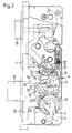
- Fig. 1 the lock cover 62 is shown broken and only the guide pin 68 'attached to the lock base 60 is visible.
- the latch tail 58 is fastened to the rear wall 70 of the housing 64 with a screw 72, which can be loosened for the purpose of changing the latch for right / left stop.
- a screw 72 which can be loosened for the purpose of changing the latch for right / left stop.
- an opening 76 is provided for the tool passage for access to the screw 72.
- the latch 78 is pulled out of the lock faceplate until it can be turned by 180 o .
- the latch nut When pulling the case 78 by the door handle, the latch nut is o pivots 80 to about 45 in the clockwise direction and integrally molded on the handle follower 80 catch 82 engages behind a shoulder 84 of the housing 64.
- the spindle hole 80 is carried toward the extended latch 78 a compression spring 88 inserted into a spring housing 86 is prestressed, the displaceable spring housing 86 engaging with a plunger 90 in a recess 92 of the follower nut 80.
- the follower nut 80 In the normal position, the follower nut 80 is supported on a pin 94 connecting the lock base 60 and the lock cover 62.
- a latch lever 96 is pivotally arranged on the lock bottom 60 coaxially with the connecting rod drive pinion 20 and rests with its free end 98 on the housing 64.
- the gear connection to the latch lever 96 comprises a driver 100 arranged on the end face of the drive rod pinion 20 on the lock bottom side, which comes into contact with a catch 102 of the latch lever 96 when the bolt 18 is locked and the lock cylinder is rotated further clockwise and pivots the latter in a clockwise direction.
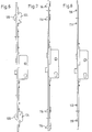
- FIGS. 4, 5 and 6 show an additional lock 104 which is provided for multiple locking and which is equipped with a hook-shaped swivel bolt 106.
- the drive rod 16 is guided in the area of the additional lock 104 with its narrow side on the faceplate 3 and bent in such a way that it bears directly against the lock ceiling.
- a toothed rack 108 is fastened (riveted) within the additional lock, which meshes with a toothed segment 110 formed on the swivel bolt 106.
- the extended swivel bolt 106 engages in a striking plate 112 on the frame in a known manner.
- the hook-shaped swivel bolts 106 are arranged in opposite directions compared to the arrangement according to FIG. 5.
- the additional bolts are designed as known, pivotable bolt tongues 114 and in FIG. 8 as locking blocks 116.
- the lock cylinder 1 is in the zero position in which the key can be inserted and removed.
- the latch 78 is in the projecting position, in which it can snap into a striking plate when the door equipped with the lock is pressed shut. This trap is biased into the projecting position by a latch spring 59 (see FIG. 1a).
- the drive rod 16 is in Fig. 1 and 1a in the open position, ie the highest possible position at all.
- the latch 18 is in the retracted position.
- the lock cylinder is rotated counterclockwise by means of the inserted key.
- the gear A is driven via the ring gear 10, so that the drive rod drive pinion 20 also rotates counterclockwise.
- the control cam 24 engages in the recess 26 'of the drive rod 16 and presses the drive rod down towards the closed position.
- the control cam 24 ' comes into engagement with the recess 26 of the drive rod 16, while the control cam 24 emerges from the recess 26'.
- the drive rod 16 has already reached its closed position shown in FIG. 2 before the stop cam 28 has stepped over the limiting finger 30. This results from FIG. 2 and there in particular from the position of the control cam 24 'relative to the projection 25 located between the two recesses 26 and 26'. It can be seen there that the drive rod 16 no longer performs a downward movement even before the control cam 24 'has reached the position shown in FIG. 2. This means, that the stop cam 28 runs with the drive rod at a standstill over the limiting finger 30 and thus reaches the position shown in FIG. 2.
- the pivot bolt 106 is also pivoted out in the counterclockwise direction, as shown in FIG. 4, in that the toothed rack 108 on the toothed segment 110 of the pivot bolt 106 rolls.
- the latch 78, the lock cylinder 1 is rotated by about 45 o clockwise. 3, the driver 100, which is mounted on the side of the drive rod drive pinion 20 facing away from the control cam 24, 24 ', engages with the nose 102 of the latch lever 96 with the result that the latch lever 96 in Is pivoted clockwise and pushes the latch 78 back over the housing 64. It should be noted that during the transition from the position according to FIGS. 1 and 1a on the one hand to the position according to FIG. 3 on the other hand the control cam 24 does not carry out a driving movement on the drive rod 16 since it with the flank of the recess 26 'formed by the projection 25 does not come into contact with driving. There is therefore no movement of the drive rod 16 when the latch 78 is withdrawn from the locking cylinder.
- the latch 78 has in its end faces 79 grooves 118 which run just outside the faceplate 3 parallel to the faceplate 3 and end at the guide ribs through which the case is guided in an opening in the faceplate. If pressure is exerted on the edge 83 with a flat bar or sheet metal in order to push the latch back, this flat bar gets into the groove 118 and prevents the latch 78 from further retracting.
- the distance of the groove 118 from the outside of the faceplate 3 is approximately 1 mm when the case 78 is fully extended.
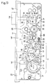
- FIGS. 11 to 15 A further aspect of the invention is now dealt with below with reference to FIGS. 11 to 15. Analog parts are numbered in FIGS. 11 to 15 with the same reference numerals as in FIGS. 1 to 3.
- the position of a transmission output gear or drive rod drive pinion 20 is defined via the gears l2, l3 and l5.
- the transmission output gear 20 has 22 cams 24 and 24 'in a dumbbell-shaped arrangement.
- the cams 24 and 24 ' are intended for engagement with a special profile P on a drive rod 16.
- the drive rod l6 is connected to drive rod sections l6a and l6b for common movement in the vertical direction.
- the special profile P has two limiting fingers 30 and 30 '.
- a stop cam 28 is also attached to the transmission output gear 20.
- the displacement of the drive rod 16 in the vertical direction is brought about by the fact that when the transmission output gear 20 is rotated, the cam 24 first engages in the recess 26 'and later the cam 24' engages in the recess 26.
- the reverse process takes place if the drive rod 16 is to be pushed back upwards by turning the gear output wheel 20 counterclockwise.
- a latch 18 is also provided. This latch 18 can be extended, as shown in Figure 15.
- a transfer lever 35 (angle lever) is provided. This transfer lever 35 pivots about an axis 34. The upper end of the transfer lever 35 is connected to the bolt 18 by a slot 38a and a pin 40.
- Two drive cams 46, 46 ' are attached to the drive rod 16. These drive cams 46, 46 'interact with a counter cam 50 of the transfer lever 35. A recess 42 is provided between the two drive cams 46 and 46 '.
- the drive cam 46 In the unlocked state shown in FIG. 11, the drive cam 46 'bears against the counter cam 50, so that the transfer lever 35 is prevented from pivoting counterclockwise about the axis 34. If the Driving rod 16 is moved downward by turning the gear output gear 20 counterclockwise (turning is initiated by the locking cylinder via the gear wheels 12, 13 and 15), the recess 42 first moves over the counter cam 50 and then the drive cam 46 runs on the counter cam 50 on. During the free immersion of the counter cam 50 in the recess 42, the position of the transfer lever 35 is not clearly determined. It can oscillate and, accordingly, the bolt 18 can freely move back and forth.
- the transfer lever 35 When the drive cam 46 runs on the counter cam 50, the transfer lever 35 is pivoted counterclockwise about the axis 34 and begins to move the bolt 18 to the left in the direction of the position shown in FIG. Even during the beginning pivoting of the transfer lever 35 in the counterclockwise direction, the position of the transfer lever 35 has not yet been clearly established. The transfer lever 35 can still swing. Only when the drive cam 46 has come into engagement with the counter cam 50 with its vertically running edge is the transfer lever 35 prevented from oscillating and the latch 18 is locked in its extreme left position (see FIG. 15). Then the lock is locked.
- the bolt 18 is retracted when the drive rod 16 moves upwards, the counter cam 50 passing through the recess 42, the flank 50 a being hit by the drive cam 46 and finally the drive cam 46 ′ again resting on the counter cam 50, as shown in FIG. 11.
- the transfer lever 35 can also oscillate again and accordingly the bolt 18 can move in an uncontrolled manner in the horizontal direction.
- the retraction of the latch 78 results from FIG. 12.
- the lockable 1a and with it the slot 2 of the ring gear 10 are so far in an approximately + 30 ° position that the trap 78 retreat can begin.
- a driver 20a is attached to the transmission output gear 20, as can be seen from FIG. This driver 20a is located on the underside of the transmission output gear 20 and therefore does not appear in FIG.
- the driver 20a is intended to cooperate with an expression 96a which is attached to a latch lever 96.
- the latch lever 96 is pivotable about the axis 32 of the transmission output wheel 20 and acts with its upper end on a latch tail 58, 64, which is also under the force of a spring 59.
- the two 360 ° rotations could no longer be carried out fully, so that the key withdrawal position could no longer be reached.
- the range of variation of the lock bit 1a in the lock according to the invention is therefore limited to the range between + 30 ° according to FIG. 14 and -90 ° according to FIG. 13. This means that - as explained above - the lock bit 1a is varied only in such an angular range can, in which there is no thrust engagement between the cam 24 and the special profile P, and consequently the drive rod 16 and the bolt 18 is not moved.
- the transfer lever 235 is modified compared to the embodiment in FIG.
- This transfer lever 235 can again be pivoted about a fixed axis 234 and has two teeth 237, 239, namely a bolt ejection tooth 237 and a bolt retraction tooth 239.
- a tooth notch 241 lies between these teeth.
- the embodiment according to FIG. 17 shows a further modification of the gear connection between the push rod 316 and the bolt 318.
- the position of the FIG. 17 again corresponds approximately to the position in FIG. 11.
- the counter cam 350 of the transfer lever 335 engages in a form-fitting manner between two correspondingly dimensioned drive cams 346 and 346 ′ of the drive rod 316.
- the lost motion between the drive rod 316 on the one hand and the transfer lever 335 and thus also the slide bolt 318 on the other hand is completely suppressed here.
- due to the unchanged engagement conditions between the cam 324 and the special profile P there is the same variation possibility for the position of the locking bar between + 30 ° and -90 °.
Abstract
Description
Die Erfindung betrifft ein Treibstangenschloß umfassend eine zwischen einer Öffnungsstellung und einer Verschlußstellung verschiebbare Treibstange in Verbindung mit mindestens einem Schließelement,
einen Schließzylinder,
ein Untersetzungsgetriebe zwischen dem Schließzylinder und der Treibstange zum Verschieben der Treibstange zwischen der Öffnungsstellung und der Verschlußstellung
und
eine Sperrvorrichtung für die Treibstange, welche die Treibstange in der Verschlußstellung gegen Verschiebung in Richtung Öffnungsstellung ohne Drehmomenteinleitung in das Untersetzungsgetriebe sperrt,
wobei auf einem getriebeausgangsseitigen Treibstangenantriebsritzel eine Steuernockenbaugruppe zum Antriebseingriff in eine Nockeneingriffsprofilierung der Treibstange angebracht ist
und
wobei ferner an dem getriebeausgangsseitigen Treibstangenantriebsritzel ein Anschlagnocken zum Angriff an einer Widerlagerfläche der Treibstange angebracht ist.The invention relates to a connecting rod lock comprising a connecting rod which can be displaced between an open position and a closed position in connection with at least one closing element.
a lock cylinder,
a reduction gear between the lock cylinder and the drive rod for moving the drive rod between the open position and the closed position
and
a locking device for the drive rod, which locks the drive rod in the closed position against displacement in the direction of the open position without introducing torque into the reduction gear,
a control cam assembly for drive engagement in a cam engagement profiling of the drive rod on a transmission output drive rod drive pinion is appropriate
and
wherein, furthermore, a stop cam for engaging on an abutment surface of the drive rod is attached to the drive rod drive pinion on the transmission output side.
Ein solches Treibstangenschloß ist aus der Europäischen Offenlegungsschrift 0 l68 001 bekannt. Es wird dort insbesondere auf die Darstellung in der Fig. 8 und auf die zu Fig. 8 zugehörigen Beschreibungsteile verwiesen.Such an espagnolette lock is known from European laid-
Bei der bekannten Ausführungsform ist auf dem Treibstangenantriebsritzel ein einziger Steuernocken angebracht, welcher mit einer einzigen Ausnehmung der Treibstange in Antriebseingriff für die Treibstange steht. Weiterhin ist bei der bekannten Ausführungsform auf dem Treibstangenantriebsritzel ein Anschlagnocken angebracht, welcher in eine weitere Ausnehmung der Treibstange zum Eingriff kommt, wenn sich die Treibstange in ihrer Öffnungsstellung befindet, so daß die Treibstange, die in der Öffnungsstellung ist und in Richtung auf ihre Schließstellung belastet wird, sich ausschließlich über den Anschlagnocken in der diesem zugehörigen Ausnehmung der Treibstange abstützt, ohne daß wesentliche Stützkräfte in das Untersetzungsgetriebe eingeleitet werden.In the known embodiment, a single control cam is attached to the drive rod drive pinion, which is in drive engagement with the drive rod for a single recess in the drive rod. Furthermore, in the known embodiment, a stop cam is attached to the drive rod drive pinion, which comes into engagement in a further recess of the drive rod when the drive rod is in its open position, so that the drive rod, which is in the open position and loads towards its closed position is supported exclusively via the stop cam in the recess of the drive rod associated therewith, without substantial supporting forces being introduced into the reduction gear.
Bei der bekannten Ausführungsform wird zum Überführen der Treibstange aus der Öffnungsstellung in die Verschlußstellung eine Drehung des Schließzylinders um 2 x 360o ausgehend von einer Null- oder Schlüsselabzugsstellung des Schließzylinders durchgeführt. Um dann noch die Treibstange in ihrer nach dieser Drehung um 2 x 360o erreichten Verschlußstellung zu blockieren, wird der Schließzylinder um weitere 360o weitergedreht; während dieser Weiterdrehung um weitere 360o gelangt dann der Anschlagnocken bei stillstehender Treibstange in die für ihn vorgesehene Ausnehmung der Treibstange.In the known embodiment, to move the drive rod from the open position into the closed position, the locking cylinder is rotated 2 × 360 °, starting from a zero or key withdrawal position of the locking cylinder. In order to then block the drive rod in its locking position reached after this rotation by 2 x 360 o , the locking cylinder is rotated further by 360 o ; during this further rotation by a further 360 ° , the stop cam then comes into the recess in the drive rod provided for it with the drive rod at a standstill.
Es wird als unbequem empfunden, daß zum Blockieren der Treibstange, nachdem deren Verschlußstellung bereits durch eine zweimalige Schließzylinderdrehung um 360o erreicht worden ist, eine weitere Schließzylinderdrehung um weitere 360o durchgeführt werden muß.It is perceived as uncomfortable that to lock the drive rod, after its locking position has already been reached by turning the lock cylinder twice by 360 ° , another lock cylinder rotation by another 360 ° must be carried out.
Der Erfindung liegt die Aufgabe zugrunde, bei einem Treibstangenschloß der eingangs bezeichneten Art eine vom Aufbau her einfachere oder zumindest gleichbleibend einfache Konstruktion anzugeben, die es erlaubt, den Übergang von der Öffnungsstellung der Treibstange bis zur Blockierung der in Verschlußstellung befindlichen Treibstange mit geringerer Umdrehungszahl am Schließzylinder durchführen zu können.The invention has for its object to provide a drive rod lock of the type mentioned a structurally simpler or at least consistently simple construction that allows the transition from the open position of the drive rod to the blocking of the drive rod in the closed position with a lower number of revolutions on the lock cylinder to be able to perform.
Zur Lösung dieser Aufgabe wird erfindungsgemäß vorgeschlagen, daß
- a) die Nockeneingriffsprofilierung mit zwei Ausnehmungen ausgeführt ist;
- b) die Antriebsnockenbaugruppe zwei auf dem Treibstangenantriebsritzel angebrachte Steuernocken aufweist, welche sukzessive in ihnen paarweise zugeordnete Ausnehmungen eingreifen;
- c) der Anschlagnocken im mittleren Bereich des Umfangsabstands zwischen den beiden Steuernocken auf dem Treibstangenantriebsritzel angeordnet ist;
- d) die in der Verschlußstellung der Treibstange steuernockenbeaufschlagte Ausnehmung mit einem Begrenzungsfinger ausgeführt ist;
- e) der Anschlagnocken in der Schließstellung der Treibstange an dem Begrenzungsfinger auf dessen von der steuernockenbeaufschlagten Ausnehmung ferner Flanke, im folgenden genannt Sperrflanke, anliegt;
- f) die Treibstange ihre Schließstellung erreicht, bevor die Schließdrehbewegung des Schließzylinders und des Treibstangenantriebsritzels beendet ist, und der Anschlagnocken nach Eintritt der Treibstange in die Schließstellung während der dann noch verfügbaren restlichen Schließdrehbewegung des Schließzylinders und des Treibstangenantriebsritzels seine Sperrstellung an der Sperrflanke des Begrenzungsfingers erreicht.
- a) the cam engagement profiling is carried out with two recesses;
- b) the drive cam assembly has two control cams mounted on the drive rod drive pinion, which successively engage recesses assigned to them in pairs;
- c) the stop cam is arranged in the central region of the circumferential distance between the two control cams on the drive rod drive pinion;
- d) the recess, which is acted upon by cam control in the closed position of the drive rod, is designed with a limiting finger;
- e) the stop cam in the closed position of the drive rod rests on the limiting finger on the flank of the control cam-actuated recess, hereinafter referred to as the locking flank;
- f) the drive rod reaches its closed position before the closing rotary movement of the lock cylinder and Espagnolette drive pinion is finished, and the stop cam reaches its locking position on the locking flank of the limiting finger after the input of the driving rod in the closed position during the remaining closing rotary movement of the locking cylinder and the driving rod drive pinion still available.
Bei der erfindungsgemäßen Ausgestaltung des Treibstangenschlosses ist es insbesondere möglich, daß die Treibstange ausgehend von der Öffnungsstellung und dementsprechend von einer Nullstellung (Schlüsselabzugsstellung) des Schließzylinders ihre Verschlußstellung nach weniger als 2 x 360o Schließzylinderdrehung erreicht, und daß die restliche Schließzylinderdrehung entsprechend dem Rest bis zu 2 x 360o zum Einfahren des Anschlagnockens in Sperrstellung gegenüber der Sperrflanke des Begrenzungsfingers dient.In the embodiment of the espagnolette lock according to the invention, it is in particular possible that the espagnolette, starting from the open position and accordingly from a zero position (key withdrawal position) of the lock cylinder, reaches its lock position after less than 2 x 360 o lock cylinder rotation, and that the remaining lock cylinder rotation corresponds to the rest up to 2 x 360 o serves to retract the stop cam in the locking position opposite the locking flank of the limiting finger.
Obwohl bei der erfindungsgemäßen Lösung ein Übergang von der Öffnungsstellung der Treibstange bis zum blockierten Zustand der in Schließstellung befindlichen Treibstange mit nur zwei Schließzylinderumdrehungen erreichbar ist, lassen sich die innerhalb des Schlosses auftretenden Kräfte gering halten und der am Schließzylinder aufzubringende Drehmomentaufwand bleibt ebenfalls gering.Although in the solution according to the invention a transition from the open position of the drive rod to the blocked state of the drive rod in the closed position can be achieved with only two lock cylinder rotations, the forces occurring within the lock can be kept low and the torque expenditure to be applied to the lock cylinder also remains low.
Um ein Maß für eine bevorzugte Bemessung des Untersetzungsverhältnisses innerhalb des Treibstangenschlosses anzugeben, sei gesagt, daß das Treibstangenantriebsritzel bei einer Schließdrehbewegung des Schließzylinders von 2 x 360o eine Schließdrehbewegung von ca. 200o ausführt. Diese Schließdrehbewegung des Treibstangenantriebsritzels wird dazu benutzt, um zum einen die Treibstange von der Öffnungsstellung in die Schließstellung zu verschieben, und um zum anderen die Treibstange in der Schließstellung dadurch zu sperren, daß der Anschlagnocken auf die Sperrflanke des Begrenzungsfingers aufläuft. Dabei kann die restliche Schließdrehbewegung des Treibstangenantriebsritzels nach Eintritt der Treibstange in die Verschlußstellung klein sein, beispielsweise ca. 20o. Dies läßt erkennen, daß für die Bewegung der Treibstange aus der Öffnungsstellung in die Schließstellung der weitaus überwiegende Anteil des Schließzylinderdrehwegs von 2 x 360o zur Verfügung steht; letzteres ist verantwortlich für ein günstiges Übersetzungsverhältnis zwischen der Bewegung des Schließzylinders einerseits und der Treibstange andererseits und damit für geringe Getriebekräfte während der Öffnungs- und Schließbewegung der Treibstange und für geringen Drehmomentaufwand an dem Schließzylinder.In order to provide a measure of a preferred design of the reduction ratio within the driving rod lock, be said that the drive rod drive pinion o a closing rotating movement of about 200 performs o during a closing rotating movement of the lock cylinder of 2 x 360th This closing rotational movement of the drive rod drive pinion is used, on the one hand, to shift the drive rod from the open position into the closed position and, on the other hand, to lock the drive rod in the closed position in that the stop cam runs onto the locking flank of the limiting finger. The remaining closing rotational movement of the drive rod drive pinion after the drive rod has entered the closed position must be small, for example approximately 20 ° . This shows that for the movement of the drive rod from the open position to the closed position, the vast majority of the lock cylinder travel of 2 x 360 o is available; the latter is responsible for a favorable transmission ratio between the movement of the lock cylinder on the one hand and the drive rod on the other hand and thus for low gear forces during the opening and closing movement of the drive rod and for low torque expenditure on the lock cylinder.
Die Steuernocken und der Anschlagnocken können im Hinblick auf einen einfachen Konstruktionsaufbau von einer Stirnseite des Treibstangenantriebsritzels axial vorspringen, wobei dann ein die Ausnehmungen tragender Teil der Treibstange an dieser Stirnseite des Treibstangenantriebsritzels anliegen kann.The control cams and the stop cams can project axially with respect to a simple construction from an end face of the drive rod drive pinion, in which case a part of the drive rod carrying the recesses can rest against this end face of the drive rod drive pinion.
Besonders günstige Kräfte und Bewegungsverhältnisse in dem Schloß ergeben sich dann, wenn die Steuernocken einen Umfangsabstand von ca. 90° haben und wenn der Umfangsabstand des Anschlagnockens von den beiden Steuernocken je ca. 135o beträgt. Hier ist zu bemerken, daß diese Winkelabstände jeweils von Nockenmitte zu Nockenmitte gerechnet sind.Particularly favorable forces and conditions of movement in the lock result when the control cams have a circumferential distance of approximately 90 ° and when the circumferential distance of the stop cam from the two control cams is approximately 135 o each. It should be noted here that these angular distances are calculated from the center of the cam to the center of the cam.
Aus Stabilitätsgründen ist es vorteilhaft, wenn die Steuernocken unter Erhaltung einer zwischen ihnen liegenden Aussparung für den Eingriff eines zwischen den beiden Ausnehmungen liegenden Vorsprungs durch einen Steg miteinander verbunden sind.For reasons of stability, it is advantageous if the control cams are connected to one another by a web while maintaining a recess between them for the engagement of a projection lying between the two recesses.
Das erfindungsgemäße Treibstangenschloß kann insbesondere in der Form hergestellt werden, daß ein quer zur Bewegungsrichtung der Treibstange beweglicher Riegel oder Hauptriegel vorgesehen ist und durch die Treibstange zwischen einer eingefahrenen Stellung und einer ausgefahrenen Stellung verschiebbar ist. Bei einer solchen Ausführungsform mit Riegel kann der Antrieb des Riegels von der Treibstange aus etwa in der Weise erfolgen, daß ein stationär gelagerter Winkelhebel mit einem ersten Arm durch eine Zapfen-Schlitzverbindung mit einem Riegelschwanz des Riegels verbunden ist, und daß ein zweiter Arm des Winkelhebels, nämlich ein Steuerarm mit einem Steuerprofil der Treibstange in Eingriff steht. Dabei kann das Steuerprofil zur Bewegungsrichtung des Riegels rechtwinklige in Abstand angeordnete Steuerflächen für das Ausfahren und das Einfahren des Riegels und eine zur Bewegungsrichtung der Treibstange im wesentlichen parallele Stirnfläche für das Sperren des ausgefahrenen Riegels aufweisen.The espagnolette lock according to the invention can be produced in particular in the form that a transom movable to the direction of movement of the espagnolette or Main bolt is provided and is displaceable between a retracted position and an extended position by the drive rod. In such an embodiment with a bolt, the bolt can be driven from the drive rod in such a way that a stationary angular lever is connected to a first arm by a pin-slot connection to a bolt tail of the bolt, and that a second arm of the angle lever , namely a control arm with a control profile of the drive rod is engaged. In this case, the control profile can have control surfaces at right angles to the direction of movement of the bolt for extending and retracting the bolt and an end surface which is essentially parallel to the direction of movement of the drive rod for locking the extended bolt.
Eine zusätzliche Sperrung des ausgefahrenen Riegels kann dadurch bewirkt werden, daß an dem Riegel eine Schulter und an der Treibstange ein Schultereingriffszapfen angebracht sind, wobei der Schultereingriffszapfen hinter der Schulter zum Riegel sperrenden Eingriff kommt, nachdem der Riegel seine voll ausgefahrene Stellung erreicht hat. Durch den gleichzeitigen Eingriff des Steuerarms mit der Stirnfläche des Steuerprofils einerseits und der Schulter mit dem Schultereingriffszapfen andererseits wird eine äußerst stabile Blockierung gegen ein gewaltsames Einwärtsschieben des Riegels erreicht, wobei sich die Stützkräfte innerhalb des Schlosses so verteilen, daß eine Beschädigung von Eingerichteteilen nicht zu befürchten ist.Additional locking of the extended latch can be accomplished by attaching a shoulder to the latch and a shoulder engaging pin on the drive rod, the shoulder engaging pin engaging behind the shoulder after the latch has reached its fully extended position. Due to the simultaneous engagement of the control arm with the end face of the control profile on the one hand and the shoulder with the shoulder engagement pin on the other hand, an extremely stable blocking against a violent pushing in of the bolt is achieved, the supporting forces being distributed within the lock in such a way that there is no fear of damage to the furnishings is.
Das Treibstangenschloß kann auch mit mindestens einem Schwenkriegel ausgerüstet sein, welcher durch die Treibstange zwischen einer eingeschwenkten und einer ausgeschwenkten Position verschwenkbar ist. Dabei kann in Weiterbildung der Erfindung zum Verschwenken des Schwenkriegels an der Treibstange eine Zahnstange angebracht sein und dementsprechend an dem Schwenkriegel ein Zahnsegment.The espagnolette lock can also be equipped with at least one pivot bolt which can be pivoted between a pivoted-in and a pivoted-out position by the drive rod. In a further development of the invention, a toothed rack can be attached to the drive rod for pivoting the swivel bolt, and accordingly a toothed segment can be attached to the swivel bolt.
Dieses Zahnsegment kann an einem Nabenteil des hakenförmig ausgebildeten Schwenkriegels angebracht sein.This toothed segment can be attached to a hub part of the hook-shaped swivel bolt.
Der Schwenkriegel selbst kann dabei Teil eines an einem Stulp des Schlosses befestigten Zusatzschlosses sein.The swivel bolt itself can be part of an additional lock attached to a faceplate of the lock.
Das erfindungsgemäß ausgebildete Schloß kann weiter mit einer Falle ausgerüstet sein, welche in bekannter Weise beim Zuschlagen der mit dem Schloß ausgerüsteten Tür in ein Schließblech selbsttätig einrastet. Diese Falle ist in üblicher Weise unter Federdruck in eine Schließstellung vorgespannt und läßt sich wahlweise durch Drehen einer Drückernuß oder von dem Schließzylinder aus in eine Öffnungsstellung zurückziehen. Dabei kann in Weiterbildung der Erfindung an dem Treibstangenantriebsritzel ein Mitnehmer angebracht sein, welcher beim Drehen des Schließzylinders über dessen der Öffnungsstellung der Treibstange entsprechende Nullstellung hinaus gegen eine Nase eines auf die Falle einwirkenden Fallhebels anschlägt.The lock designed according to the invention can further be equipped with a latch which, in a known manner, automatically engages in a striking plate when the door equipped with the lock slams shut. This case is biased in a conventional manner under spring pressure into a closed position and can be pulled back into an open position either by turning a follower nut or from the lock cylinder. In a further development of the invention, a driver can be attached to the drive rod drive pinion, which, when the locking cylinder is rotated, strikes beyond its zero position corresponding to the open position of the drive rod, against a nose of a drop lever acting on the latch.
Die Falle kann grundsätzlich üblicher prismatischer Bauform sein, d.h. daß die Falle in einer zur Türschloßebene senkrechten und zur Bewegungsrichtung der Falle parallelen Schnittebene betrachtet einen Dreiecksquerschnitt mit einer Fallenanlaufschräge und einer Fallenrastflanke aufweist, und d.h. weiter, daß die Falle zu dieser Schnittebene im wesentlichen parallele Endflächen aufweist. Bei einer solchen Ausbildung der Falle hat sich gezeigt, daß unbefugte Öffnungsversuche in der Weise möglich sind, daß ein Flachstab oder ein Blech in den Zwischenraum zwischen Schließblech und Stulp eingeführt und derart schräg bewegt wird, daß es mit einer Kante auf eine Fallenkante einwirkt, welche durch die Fallenanlaufschräge einerseits und eine der Endflächen andererseits gebildet ist. Auf diese Weise kann dann die Falle zurückgedrückt werden. Um ein solches Zurückdrücken der Falle zu verhindern, wird weiter vorgeschlagen, daß in den durch die Endflächen und durch die Fallenanlaufschräge gebildeten Kantenbereichen, welche bei ausgefahrener Falle dicht vor der Stulpaußenfläche liegen, Ausnehmungen vorgesehen sind. Wird dann ein Flachstab oder ein Blech in der oben beschriebenen Weise zu einem unbefugten Öffnungsversuch herangezogen, so verhakt sich die auf die Falle auflaufende Kante des Flachstabs bzw. des Bleches an der Ausnehmung der Kante der Falle, so daß das Zurückdrängen der Falle nach einem kurzen Weg zum Stillstand kommt und blockiert bleibt.The latch can basically be of the usual prismatic design, that is to say that the latch in a sectional plane perpendicular to the door lock plane and parallel to the direction of movement of the latch has a triangular cross-section with a latch start slope and a latch latch flank, and furthermore that the latch is essentially parallel to this sectional plane having. With such a design of the trap it has been shown that unauthorized attempts to open it are possible in such a way that a flat bar or a plate is inserted into the space between the striking plate and the faceplate and is moved obliquely such that it acts with an edge on a trap edge, which is formed by the trap ramp on the one hand and one of the end faces on the other. The trap can then be pushed back in this way. In order to prevent such a pushing back of the trap, it is further proposed that in the through the end faces and recesses are provided by the edge areas formed by the latch stop, which lie close to the outer face surface when the latch is extended. If a flat bar or a sheet is then used in the manner described above for an unauthorized attempt to open, the edge of the flat bar or sheet that runs onto the trap hooks on the recess of the edge of the case, so that the case is pushed back after a short Path comes to a standstill and remains blocked.
Die vorstehend erwähnte erfindungsgemäße Ausbildung der Falle soll unabhängig von den vorausgehend diskutierten Merkmalen des Treibstangenschlosses Schutz genießen.The above-mentioned design of the latch should enjoy protection regardless of the features of the espagnolette lock discussed above.
Die Ausnehmungen an der Falle können insbesondere als Nuten ausgebildet sein, welche parallel zur Stulpaußenfläche verlaufen und bei Vorhandensein von längs der Fallenrastflanke und längs der Endflächen der Falle verlaufenden Fallenführungsrippen vor oder an diesen Fallenführungsrippen enden. Damit bleiben die Fallenführungsrippen unversehrt, und es besteht keine Gefahr, daß sie beim Zurückziehen der Falle in den Führungen des Stulps verhaken.The recesses on the trap can in particular be designed as grooves which run parallel to the outer surface of the faceplate and, in the presence of trap guide ribs running along the latch latch flank and along the end surfaces of the trap, end in front of or on these trap guide ribs. The trap guide ribs thus remain intact and there is no danger that they will get caught in the guides of the cuff when the trap is pulled back.
Nach einem anderen Aspekt der Erfindung wird ausgegangen von einem Treibstangenschloß, umfassend eine zwischen einer Öffnungsstellung und einer Verschlußstellung verschiebbare Treibstange in Verbindung mit mindestens einem Schließelement,
einen Schließzylinder,
ein Untersetzungsgetriebe zwischen dem Schließzylinder und der Treibstange zum Verschieben der Treibstange zwischen der Öffnungsstellung und der Verschlußstellung,
wobei das Untersetzungsgetriebe schließzylinderseitig einen Zahnkranz besitzt, welcher mit zwei ihm nachgeordneten Abtriebsrädern kämmt und einen zum Einstecken des Schließbarts des Schließzylinders ausgebildeten, zum Rand hin offenen Schlitz aufweist, und wobei ein um eine ortsfeste Achse drehbares Treibstangenantriebsglied des Untersetzungsgetriebes über eine Mitnahmeeinrichtung auf die Treibstange einwirkt,
ferner umfassend
einen Riegel, welcher quer zur Längsachse der Treibstange zwischen einer eingefahrenen Stellung und einer ausgefahrenen Stellung verschiebbar und durch Bewegungsumsetzmittel von der Treibstange her antreibbar ist,
unferner umfassend
eine durch Federkraft in eine Schließstellung vorgespannte Falle, welche zum einen von einer Drückernuß her und zum anderen von dem Schließzylinder her gegen die Federkraft zurückziehbar ist, wobei der Schlitz des Zahnkranzes aus seiner Nullgradstellung heraus in mindestens einer Drehrichtung über einen Variationswinkelbereich des Schließbarts verstellbar ist, ohne daß eine Verstellung des Riegels eintritt.According to another aspect of the invention, the starting point is a connecting rod lock comprising a connecting rod which can be displaced between an open position and a closed position in connection with at least one closing element,
a lock cylinder,
a reduction gear between the lock cylinder and the drive rod for moving the drive rod between the open position and the closed position,
wherein the reduction gear on the lock cylinder side has a toothed ring which meshes with two output gears arranged downstream of it and has a slot designed to insert the locking bar of the lock cylinder and is open towards the edge, and wherein a drive rod drive member of the reduction gear rotatable about a fixed axis acts on the drive rod via a driving device ,
further comprehensive
a bolt which can be moved transversely to the longitudinal axis of the drive rod between a retracted position and an extended position and can be driven from the drive rod by means of movement conversion means,
more comprehensive
a case biased by spring force into a closed position, which can be retracted against the spring force from a follower and from the lock cylinder, the slot of the ring gear being adjustable from its zero degree position in at least one direction of rotation over a variation angle range of the lock bit, without the bolt being adjusted.
Ein solches Treibstangenschoß ist aus der DE-PS 29 19 201 bekannt.Such a drive rod lap is known from DE-PS 29 19 201.
Bei dem bekannten Treibstangenschloß ist die Verstellung des Schubriegels bei einem Verschwenken des Schlitzes des Zahnkranzes aus seiner Nullgradstellung heraus durch den Variationswinkelbereich des Schließbarts dadurch ermöglicht, daß die Bewegungsumsetzmittel zwischen dem Riegel und der Treibstange von einem Schrägschlitz der Treibstange und einem Schlitzfolgerbolzen des Schubriegels gebildet sind und daß der Schrägschlitz der Treibstange durch eine in Bewegungsrichtung der Treibstange verlaufenden Nische ergänzt ist, in welche der Zapfen des Schubriegels in der zurückgeschlossenen Endstellung des Schubriegels eingetreten ist, und axiales Bewegungsspiel besitzt.In the known espagnolette lock, the adjustment of the slide bolt is when pivoting of the slot of the ring gear from its zero degree position by the variation angle range of the locking bar enables that the movement conversion means between the bolt and the drive rod are formed by an oblique slot of the drive rod and a slot follower bolt of the slide bolt and that the oblique slot of the drive rod by a extending in the direction of movement of the drive rod Niche is added, in which the pin of the slide bolt has entered in the closed end position of the slide bolt, and has axial play.
Die Falle ist bei dieser bekannten Lösung von der Treibstange her angetrieben. Zum Zurückholen der Falle wird die Treibstange vom Schließzylinder aus bewegt und nimmt dabei die Falle mit zurück, wobei der Schubriegel dank des Bewegungsspiels seines Zapfens in der Nische still steht. Diese Ausführungsform ist mit erheblichen Nachteilen belastet: Zum Zurückziehen der Falle muß stets die Treibstange mit bewegt werden. Dies bedeutet zusätzlichen Kraftaufwand und zusätzliche Abnutzungserscheinungen in dem Treibstangenschloß und erfordert zusätzliche Anpassung der rahmenseitigen Riegelbleche, um den treibstangenseitigen Verriegelungselementen bei der für den Fallenrückzug notwendigen Treibstangenbewegung ein entsprechendes Bewegungsspiel zu gewähren. Nachteilig ist darüber hinaus, daß in der Offenstellung des Schlosses bei Einstellung des Schließzylinders in die Schlüsselabzugsstellung und gezogenem Schlüssel eine Einwirkung auf die Treibstange etwa im Rahmen eines Einbruchversuchs zu einer Rückwirkung über das Getriebe bis zum Schließzylinder führen kann mit der Folge, dar die Zuhaltungen des Schließzylinders belastet werden.In this known solution, the trap is driven by the drive rod. To retrieve the trap, the drive rod is moved from the locking cylinder and takes the trap back with it, the slide bolt standing still in the niche thanks to the play of its pin. This embodiment is burdened with considerable disadvantages: to retract the trap, the drive rod must always be moved. This means additional effort and additional wear and tear in the espagnolette lock and requires additional adjustment of the frame-side locking plates in order to grant the espagnolette-side locking elements a corresponding movement play during the espagnolette movement necessary for the latch retraction. Another disadvantage is that in the open position of the lock when the lock cylinder is set to the key withdrawal position and the key removed, an action on the drive rod, for example as part of an attempted break-in, can lead to a reaction via the gearbox to the lock cylinder, with the result that the tumblers of the Lock cylinder be loaded.
Der Erfindung liegt die Aufgabe zugrunde, unter Beibehaltung des Variationswinkelbereichs für den Schließzylinderbart und unter Beibehaltung der Unbeweglichkeit des Schubriegels bei Verstellungen des Schließzylinderbarts innerhalb dieses Variationswinkelbereichs eine Lösung zu finden, bei welcher Einwirkungen auf die in Öffnungsstellung befindliche Treibstange nicht zur Schließzylinderbelastung führen und die Treibstange beim Zurückholen der Falle vom Schließzylinder aus still steht.The invention has for its object to find a solution while maintaining the variation angle range for the lock cylinder bit and while maintaining the immobility of the slide bolt when adjusting the lock cylinder bar within this variation angle range, in which effects on the drive rod in the open position do not lead to the lock cylinder load and the drive rod when Retrieving the latch from the lock cylinder stands still.
Zur Lösung dieser Aufgabe wird vorgeschlagen, daß eine an dem Treibstangenantriebsglied angebrachte Nockenbaugruppe mit zwei Steuernocken und einem Anschlagnocken und eine an der Treibstange angebrachte Nockeneingriffsprofilierung mit zwei den Steuernocken paarweise zugehörigen Ausnehmungen und zwei Begrenzungsfingern beidseits der Ausnehmungen derart ausgebildet sind, daß bei einer Verdrehung des Zahnkranzes innerhalb des Variationswinkelbereichs des Schließbarts die Mitnahmeverbindung des für den Beginn der Treibstangenverschiebung aus der Öffnungsstellung in die Verschlußstellung verantwortlichen Steuernockens mit der zugehörigen Ausnehmung gelöst ist und der dieser Ausnehmung zugehörige Begrenzungsfinger die Verschiebung der Treibstange im wesentlichen sperrend zwischen den Anschlagnocken und die Achse des Treibstangenantriebsglieds eingreift,
und daß die Falle durch einen Mitnehmer des Treibstangenantriebsglieds zurückziehbar ist.To solve this problem, it is proposed that a cam assembly attached to the drive rod drive member with two control cams and a stop cam and a cam engagement profile attached to the drive rod with two recesses associated with the control cams and two limiting fingers be formed on both sides of the recesses in such a way that when the toothed ring is rotated within the variation angle range of the locking bar, the driving connection of the control cam responsible for the start of the drive rod displacement from the open position into the closed position with the associated recess is released and the limiting finger associated with this recess interferes with the displacement of the drive rod between the stop cams and the axis of the drive rod drive member in a substantially blocking manner,
and that the trap is retractable by a driver of the drive rod drive member.
Dabei können die Bewegungsumsetzmittel zwischen dem Riegel und der Treibstange einen am Schloßgehäuse schwenkbar gelagerten Umsetzhebel umfassen, welcher einerseits mit der Treibstange verzahnungsartig im Eingriff steht und andererseits mit dem Riegel durch eine Zapfen/Schlitzverbindung in Verbindung stehen.The movement conversion means between the bolt and the drive rod can comprise a conversion lever pivotally mounted on the lock housing, which on the one hand engages with the drive rod in a tooth-like manner and on the other hand is connected to the bolt by a pin / slot connection.
Um bei geringstem Raumbedarf, insbesondere im Hinblick auf den Abstand der Stulpschiene von dem Schließzylinder und der Drückernuß, das einer zweitouringen Drehung des Schließzylinderkerns entsprechende Übersetzungsverhältnis zwischen der Treibstange und dem Riegel zu erzielen, kann man vorsehen, daß der verzahnungsartige Eingriff zwischen der Treibstange und dem Umsetzhebel totgangbehaftet ist.In order to achieve the transmission ratio between the drive rod and the bolt corresponding to a two-speed rotation of the lock cylinder core in order to achieve the smallest possible space requirement, in particular with regard to the distance of the faceplate from the lock cylinder and the follower nut, it can be provided that the tooth-like engagement between the drive rod and the Transfer lever has lost motion.
Nach einer ersten Ausführungsform der Umsetzhebellösung ist vorgesehen, daß der Umsetzhebel ein Doppelhebel ist, welcher mit einem Gegennocken in Eingriff mit einer Verzahnung der Treibstange steht und in einem Arm einen Schlitz aufweist, welcher einen Zapfen des Riegels eingabelt. Dabei kann die Verzahnung zwei durch eine Totgang gewährende Ausnehmung beabstandete Antriebsnocken aufweisen, nämlich einen riegelausschiebenden Antriebsnocken und einen riegelrückziehenden Antriebsnocken.According to a first embodiment of the transfer lever solution, it is provided that the transfer lever is a double lever, which is in engagement with a counter cam with a toothing of the drive rod and has a slot in an arm, which feeds in a pin of the bolt. In this case, the toothing can have two drive cams spaced apart by a lost motion, namely a bolt-extending drive cam and a bolt-retracting drive cam.
Nach einer anderen Ausführungsform der Umsetzhebellösung ist vorgesehen, daß der verzahnungsartige Eingriff zwischen der Treibstange und dem Umsetzhebel durch eine Nase der Treibstange einerseits und zwei durch eine Zahnkerbe getrennte Zähne des Umsetzhebels andererseits gebildet ist und daß der Umsetzhebel einen Riegeleingriffsarm aufweist, welcher mit einem Zapfen in ein Langloch des Riegels eingreift. Dabei kann die Zahnkerbe als eine Totgang gewährende Zahnkerbe ausgebildet sein.According to another embodiment of the transfer lever solution it is provided that the tooth-like engagement between the drive rod and the transfer lever is formed by a nose of the drive rod on the one hand and two teeth of the transfer lever separated by a tooth notch on the other hand and that the transfer lever has a latch engagement arm which with a pin in an elongated hole of the bolt engages. The tooth notch can be designed as a tooth notch which guarantees lost motion.
Die beiliegenden Figuren erläutern die Erfindung anhand von Ausführungsbeispielen. Es stellen dar:
- Fig. 1
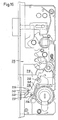
- eine Ansicht, teilweise aufgebrochen, eines erfindungsgemäßen Treibstangenschlosses in der Öffnungsstellung;
- Fig. 1a
- eine Vergrößerung zu Fig. 1;
- Fig. 2
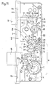
- eine Ansicht entsprechend Fig. 1 in der Verschlußstellung der Treibstange;
- Fig. 3
- eine Ansicht entsprechend Fig. 1 bei Rückziehung der Falle durch Drehen des Schließzylinders;
- Fig. 4
- ein Zusatzschloß mit einem Schwenkriegel;
- Fig. 5
- eine Stulpschienentreibstangeneinheit mit einem erfindungsgemäßen Treibstangenschloß und zwei Zusatzschlössern;
- Fig. 6
- eine Anordnung entsprechend Fig. 5 mit gegenläufigen Schwenkriegeln;
- Fig. 7
- eine Anordnung entsprechend Fig. 5 mit abgewandelten Schwenkriegeln;
- Fig. 8
- eine Anordnung entsprechend Fig. 5 mit an der Treibstange starr befestigten Schließkloben;
- Fig. 9
- eine Anordnung entsprechend Fig. 1 mit einer abgewandelten Gestaltung der Falle;
- Fig. 10
- eine Draufsicht auf die Falle in Pfeilrichtunng X der Fig. 9;
- Fig. ll
- eine Ausführungsform entsprechend den Figuren l und la in einem Getriebezustand, in dem sich der Schließbart in der Nullgradstellung befindet und der Schlüssel gesteckt und gezogen werden kann;
- Fig. l2
- den Beginn des Fallenrückzugs bei der Ausführungsform nach Figur ll in einer anderen Schnittebene;
- Fig. l3
- eine Abwandlung zur Ausführungsform nach Figur ll unter Verwendung eines Schließzylinders mit einem in der Schlüsselabzugsstellung unter einem Winkel von - 90o seitlich abstehenden Schließbart;
- Fig. l4
- eine Abwandlung zu Figur ll mit einem in der Schlüsselabzugsstellung unter + 30o seitlich abstehenden Schließbart;
- Fig. l5
- ein Schloß gemäß Figur ll bei vorgeschlossenen Schubriegel und
- Fig. 16 und 17
- weitere Ausführungsformen für die getriebliche Verbindung zwischen der Treibstange und dem Riegel.
- Fig. 1
- a view, partly broken away, of an espagnolette lock according to the invention in the open position;
- Fig. 1a
- an enlargement to Fig. 1;
- Fig. 2
- a view corresponding to Figure 1 in the closed position of the drive rod.
- Fig. 3
- a view corresponding to Figure 1 when retracting the trap by turning the lock cylinder.
- Fig. 4
- an additional lock with a swivel bolt;
- Fig. 5
- a faceplate drive rod unit with an inventive drive rod lock and two additional locks;
- Fig. 6
- an arrangement corresponding to Figure 5 with counter-rotating swivel bolts.
- Fig. 7
- an arrangement corresponding to Figure 5 with modified swivel bolts.
- Fig. 8
- an arrangement corresponding to FIG 5 with the locking rod rigidly attached to the drive rod.
- Fig. 9
- an arrangement corresponding to Figure 1 with a modified design of the trap.
- Fig. 10
- a plan view of the trap in arrow direction X of Fig. 9;
- Fig. Ll
- an embodiment according to Figures l and la in a gear state, in which the lock bit is in the zero degree position and the key can be inserted and removed;
- Fig. L2
- the beginning of the retraction of the trap in the embodiment according to FIG. 11 in a different sectional plane;
- Fig. L3
- a modification of the embodiment according to Figure II using a lock cylinder with a lock bit protruding laterally in the key withdrawal position at an angle of - 90 o ;
- Fig. 14
- a modification to Figure 11 with a locking bit which projects laterally in the key withdrawal position below + 30 o ;
- Fig. L5
- a lock according to Figure ll with pre-closed slide bolt and
- 16 and 17
- further embodiments for the gear connection between the drive rod and the bolt.
Wie in Fig. 1 und 1a dargestellt, ist die Schließbartnabe (nicht dargestellt) des Profilzylinders 1 von einem Zahnkranz 10 umgeben, der für die Kupplung mit dem Schließbart einen Schlitz 2 aufweist, wobei der Drehkreisdurchmesser des Schließbarts im Bereich der beiden Abtriebszahnräder 12, 12' kleiner ist als der Fußkreisdurchmesser des Zahnkranzes 10. Der Zahnkranz 10 ist mit einem Flansch am Außenumfang in einem gehäusefesten Lager 14 geführt und kämmt mit den beiden Abtriebszahnrädern 12, 12'.As shown in FIGS. 1 and 1a, the lock bit hub (not shown) of the
Die Verriegelungs- und Entriegelungsbetätigung der Treibstange 16 und des Riegels 18 erfolgt durch jeweils zwei Drehungen des Schließzylinders 1. Am Ende eines Untersetzungsgetriebes A, welches von den Zahnrädern 10, 12 - 12', 13 und 15 gebildet ist, ist ein Treibstangenantriebsritzel 20 mit einem an der schloßdeckenseitigen Stirnseite fest angeordneten Steuerelement 22 gelagert. Das Steuerelement 22 ist an beiden Enden mit annähernd kreisförmig geformten Steuernocken 24, 24' ausgebildet, welche bei Schließbetätigung durch den Schließzylinder nacheinander in korrespondierende Ausnehmungen 26, 26' der Treibstange 16 eingreifen und diese verschieben.The locking and unlocking actuation of the
An der schloßdeckenseitigen Stirnseite des Ritzels 20 ist weiterhin ein Anschlagnocken 28 diametral zum Steuerelement 22 angeformt. Die Ausnehmungen 26, 26' der Treibstange 16 für den Eingriff der Steuernocken 24, 24' sind an den Außenseiten durch in das Schloßinnere gerichtete, gekrümmte Begrenzungsfinger 30, 30' begrenzt, welche sich annähernd bis zur Drehachse 32 des Treibstangenantriebsritzels 20 erstrecken.A
Bei in Verschlußstellung verschobener Treibstange 16 (Fig. 2) ist der obere Begrenzungsfinger 30 unter den Anschlagnocken 28 gefahren. Bei in dieser Position auf die Treibstange 16 wirkenden Rückstellkräften stützt sich der Begrenzungsfinger 30 an dem Anschlagnocken 28 ab, wodurch diese Kräfte in die Achse 32 des Treibstangenantriebsritzels 20 eingeleitet werden. Die Rückstellkräfte übertragen sich demzufolge nicht als Drehmoment auf das Getriebe A und auf den Schließzylinder 1.With the
Auf der Achse 34 des nahe der Treibstange 16 angeordneten Zahnrades 12 ist koaxial dazu ein Winkelhebel 35 schwenkbar gelagert, welcher einen Riegelschwanz 36 teilweise übergreift. Er umfaßt mit einem gabelartig ausgebildeten Arm 38 einen Zapfen 40. Ein zweiter Arm 50 des Winkelhebels 35 ragt in eine Treibstangenausnehmung 42 der Treibstange 16, welche von mit rechtwinkligen Steuerflächen 44, 44' versehenen Nocken 46, 46' begrenzt ist.On the
Beim Ausschließen der Treibstange 16 und des Riegels 18 kommt die untere Steuerfläche 44 des oberen Nocken 46 an dem zweiten Arm 50 des Winkelhebels 35 zur Anlage und verschwenkt ihn entgegen dem Uhrzeigersinn in die Stellung gemäß Fig. 2. Durch die Zapfen-Schlitzverbindung 38, 40 wird der Riegel ausgeschlossen. Nach zweifacher Schließdrehung des Profilzylinders 1 ist der Riegel 18 voll ausgefahren, und der Arm 50 stützt sich dann auf der Stirnfläche 52 des oberen Nocken 46 ab (Fig. 2). Gleichzeitig ist ein treibstangenfester Zapfen 54 (Fig. 2) hinter eine Schulter 56 des Riegels 18 geschoben.When the
Wenn jetzt der Versuch unternommen wird, den Riegel in das Schloßgehäuse zurückzuschieben, dann werden die auftretenden Kräfte über den Riegelzapfen 40 in den Winkelhebel 35 eingeleitet und versuchen, den Winkelhebel im Uhrzeigersinn zu verschwenken. Da aber das freie Ende 50 des Winkelhebels 35 sich an dem oberen Nocken 46 abstützt, wird die Schwenkbewegung blockiert. Durch den gleichzeitig hinter die Schulter 56 geschobenen Zapfen 54 werden die auf den Riegel 18 einwirkenden Kräfte auch auf die Treibstange 16 übertragen (Wirkrichtung der Kraft in der Zeichnungsebene nach rechts), welche ihrerseits in entgegengesetzter Richtung von dem Arm 50 des Winkelhebels 35 (Wirkrichtung der Gegenkraft nach links) abgestützt wird. Getriebe und Schließzylinder bleiben somit von den genannten Kräften entlastet.If an attempt is now made to push the bolt back into the lock housing, then the forces which occur are introduced via the
Die Fallensteuerung der Falle 78 (Fig. 3) kann von der Drückernuß 80 eines Türdrückers und/oder vom Schließzylinder 1 aus vorgenommen werden. Der Fallenschwanz 58 ist in einem zwischen Schloßboden 60 und Schloßdecke 62 verschiebbaren Gehäuse 64 befestigt, wobei das Gehäuse 64 zur Führung auf seinen Breitseiten zwei sich gegenüberliegende Längsschlitze 66, 66' aufweist, in welche jeweils am Schloßboden 60 und an der Schloßdecke 62 angeordnete kurze Führungszapfen 68, 68' eingreifen. In Fig. 1 ist die Schloßdecke 62 aufgebrochen dargestellt und nur der am Schloßboden 60 befestigte Führungszapfen 68' ist sichtbar. Der Fallenschwanz 58 ist an der rückseitigen Wand 70 des Gehäuses 64 mit einer Schraube 72 befestigt, welche zum Zwecke der Fallenumstellung für Rechts-/Linksanschlag gelöst werden kann. In der der Schloßstulp 3 gegenüberliegenden schmalen Gehäuserückwand 74 ist für den Zugang zur Schraube 72 eine Öffnung 76 für den Werkzeugdurchgriff vorgesehen. Die Falle 78 wird für die Umstellung so weit aus der Schloßstulp herausgezogen, bis ein Verdrehen um 180o möglich ist.The latch control of the latch 78 (FIG. 3) can be carried out from the
Beim Einziehen der Falle 78 durch den Türdrücker wird die Drückernuß 80 um ca. 45o im Uhrzeigersinn verschwenkt und ein an der Drückernuß 80 einstückig angeformter Mitnehmer 82 greift hinter eine Schulter 84 des Gehäuses 64. Die Drückernuß 80 ist in Richtung der ausgefahrenen Falle 78 durch eine in ein Federgehäuse 86 eingesetzte Druckfeder 88 vorgespannt, wobei das verschiebbare Federgehäuse 86 mit einem Stößel 90 in einer Aufnehmung 92 der Drückernuß 80 eingreift. Die Drückernuß 80 stützt sich in Normalstellung an einem den Schloßboden 60 und die Schloßdecke 62 verbindenden Zapfen 94 ab.When pulling the
Für die Fallenbetätigung mittels Schließzylinder 1 ist am Schloßboden 60 koaxial zum Treibstangenantriebsritzel 20 ein Fallenhebel 96 schwenkbar angeordnet, welcher mit seinem freien Ende 98 an dem Gehäuse 64 anliegt. Die Getriebeverbindung zum Fallenhebel 96 umfaßt einen an der schloßbodenseitigen Stirnseite des Treibstangenritzels 20 angeordneten Mitnehmer 100, der bei eingeschlossenem Riegel 18 und weiterer Drehung des Schließzylinders im Uhrzeigersinn an einer Nase 102 des Fallenhebels 96 zur Anlage kommt und letzteren im Uhrzeigersinn verschwenkt.For the latch actuation by means of the
In den Figuren 4, 5 und 6 ist ein für eine Mehrfachverriegelung vorgesehenes Zusatzschloß 104 dargestellt, welches mit einem hakenförmigen Schwenkriegel 106 ausgerüstet ist. Die Treibstange 16 ist im Bereich des Zusatzschlosses 104 mit ihrer Schmalseite an der Stulpschiene 3 geführt und derart abgekröpft, daß sie unmittelbar an der Schloßdecke verschiebbar anliegt. Auf der von der Schloßdecke abgewandten Breitseite der Treibstange 16 ist innerhalb des Zusatzschlosses eine Zahnstange 108 befestigt (angenietet), welche mit einem an dem Schwenkriegel 106 angeformten Zahnsegment 110 in Eingriff steht. Der ausgefahrene Schwenkriegel 106 greift in bekannter Weise in ein rahmenseitiges Schließblech 112 ein.FIGS. 4, 5 and 6 show an
In Fig. 6 sind die hakenförmigen Schwenkriegel 106 im Vergleich zur Anordnung gemäß Fig. 5 gegenläufig angeordnet.In FIG. 6, the hook-shaped
In Fig. 7 sind die zusätzlichen Riegel als bekannte, schwenkbare Riegelzungen 114 und in Fig. 8 als Schließkloben 116 ausgebildet.In FIG. 7, the additional bolts are designed as known,
Die verschiedenen Funktionen des Treibstangenschlosses sind wie folgt:
In den Figuren 1 und 1a befindet sich der Schließzylinder 1 in der Nullage, in welcher der Schlüssel gesteckt und gezogen werden kann. Die Falle 78 befindet sich in der vorspringenden Stellung, in der sie in ein Schließblech einrasten kann, wenn die mit dem Schloß ausgerüstet te Türe zugedrückt wird. Diese Falle ist durch eine Fallenfeder 59 (siehe Fig. 1a) in die vorspringende Stellung vorgespannt. Die Treibstange 16 befindet sich in Fig. 1 und 1a in der Öffnungsstellung, d.i. der höchstmöglichen Stellung überhaupt. Der Riegel 18 befindet sich in der zurückgezogenen Stellung.The different functions of the espagnolette lock are as follows:
In Figures 1 and 1a, the
Zum Überführen der Treibstange 16 in die Schließstellung wird der Schließzylinder mittels des eingesteckten Schlüssels im Gegenzeigersinn verdreht. Über den Zahnkranz 10 wird dabei das Getriebe A angetrieben, so daß sich das Treibstangenantriebsritzel 20 ebenfalls im Gegenzeigersinn dreht. Dabei greift der Steuernocken 24 in die Ausnehmung 26' der Treibstange 16 ein und drückt die Treibstange nach unten in Richtung auf die Verschlußstellung. Im Verlaufe des Weiterdrehens des Schließzylinders im Gegenzeigersinn kommt der Steuernocken 24' in Eingriff mit der Ausnehmung 26 der Treibstange 16, während der Steuernocken 24 aus der Ausnehmung 26' austritt.To transfer the
Nach einer Schließzylinderumdrehung von 2 x 360o ist der Zustand gemäß Fig. 2 erreicht, in welchem die Treibstange 16 ihre Verschlußstellung, d.h. ihre tiefste Stellung erreicht hat. Der Anschlagnocken 28 liegt an der Sperrflanke 31 des Begrenzungsfingers 30 an, so daß bei einem Versuch die Treibstange 16 nach aufwärts zu schieben der Begrenzungsfinger 30 gegen den Anschlagnocken 28 anstößt und eine Aufwärtsverschiebung der Treibstange 16 somit blockiert ist. Die Blockierungskraft wird dabei in radialer Richtung bezogen auf das Treibstangenantriebsrad 20 unmittelbar in die Drehachse 32 des Treibstangenantriebsritzels 20 eingeleitet und wirkt sich nicht als ein Drehmoment aus, welches in das Untersetzungsgetriebe A eingeleitet wird.After a lock cylinder rotation of 2 × 360 ° , the state according to FIG. 2 is reached, in which the
Die Treibstange 16 hat ihre in der Fig. 2 dargestellte Verschlußstellung bereits erreicht, bevor der Anschlagnocken 28 über den Begrenzungsfinger 30 getreten ist. Dies ergibt sich aus der Fig. 2 und dort insbesondere aus der Stellung des Steuernockens 24' gegenüber dem zwischen den beiden Ausnehmungen 26 und 26' gelegenen Vorsprung 25. Man erkennt dort, daß die Treibstange 16 keine Abwärtsbewegung mehr ausführt, schon bevor der Steuernocken 24' die Stellung gemäß Fig. 2 erreicht hat. Dies bedeutet, daß der Anschlagnocken 28 bei stillstehender Treibstange über den Begrenzungsfinger 30 läuft und so die in Fig. 2 dargestellte Position erreicht.The
Während der Abwärtsbewegung der Treibstange 16 von der Position gemäß Fig. 1 in die Verschlußstellung gemäß Fig. 2 trifft die Steuerfläche 44 des Nockens 46 auf den zweiten Arm 50 des Winkelhebels 35 und verdreht diesen entgegen dem Uhrzeigersinn, so daß über die Zapfen-Schlitzverbindung 38, 40 der Riegelschwanz 36 und damit der Riegel 18 nach links in seine Verschlußstellung verschoben wird. Der Beginn dieser Verschiebung hängt von der Lage der Steuerfläche 44 gegenüber der Achse 34 des Winkelhebels 35 ab. Infolge der Verschwenkung des Winkelhebels 35 gelangt dann schließlich der zweite Arm 50 des Winkelhebels 35 auf die Stirnfläche 52 des Nockens 46. Dann tritt eine weitere Verschwenkung des Winkelhebels 35 im Gegenzeigersinn nicht mehr ein, auch wenn die Treibstange 16 noch weiter nach unten verschoben wird. Ein Zurückschieben des Riegels 18 ist aber nicht mehr möglich, weil ein solches Zurückschieben des Riegels 18 ein Verschwenken des Winkelhebels 35 im Uhrzeigersinn zur Folge hätte, das durch das Anliegen des zweiten Arms 50 an der Stirnfläche 52 unterbunden ist. Die Treibstange 16 bewegt sich angetrieben durch den Schließzylinder 1 noch weiter nach unten, nachdem der Riegel 18 bereits seine voll ausgefahrene Endstellung erreicht hat. Dabei gelangt,wie in Fig. 2 dargestellt, der Zapfen 54 der Treibstange 16 hinter die Schulter 56 des Riegels 18. Dann ist ein Zurückschieben des Riegels 18 auch durch den Zapfen 54 verhindert. Die Treibstange 16 ist dabei im Bereich des Zapfens 54 dadurch stabilisiert, daß sie mit der Stirnfläche 52 des Nockens 46 an dem zweiten Arm 50 des Winkelhebels 35 anliegt, der seinerseits durch die Zapfen-Schlitzverbindung 38, 40 gestützt ist.During the downward movement of the
Während der Abwärtsbewegung der Treibstange 16 aus der Öffnungsstellung gemäß Fig. 1 und 1a in die Schließstellung gemäß Fig. 2 wird ferner, wie in Fig. 4 dargestellt, der Schwenkriegel 106 im Gegenzeigersinn ausgeschwenkt, dadurch, daß sich die Zahnstange 108 an dem Zahnsegment 110 des Schwenkriegels 106 abwälzt.During the downward movement of the
Beim Zurückführen der Treibstange 16 aus der Verschlußstellung gemäß Fig. 2 in die Öffnungsstellung gemäß Fig. 1 und 1a beginnt die Aufwärtsbewegung der Treibstange 16 wie aus Fig. 2 ersichtlich erst, nachdem der Anschlagnokken 28 die Sperrflanke 31 des Begrenzungsfingers 30 wieder verlassen hat, weil der Steuernocken 24' erst nach einer Anfangsdrehung des Treibstangenantriebsritzels 20 mit der von dem Begrenzungsfinger 30 gebildeten oberen Flanke der Ausnehmung 26 wieder in Eingriff kommt. Durch weiteres Verdrehen des Schließzylinders im Uhrzeigersinn wird dann der Zustand gemäß Fig. 1 und 1a wieder erreicht.When the
Wenn ausgehend von dem Zustand der Fig. 1 und 1a die Falle 78 zurückgezogen werden soll, so wird der Schließzylinder 1 um ca. 45o im Uhrzeigersinn verdreht. Dabei gelangt, wie in Fig. 3 dargestellt, der Mitnehmer 100, welcher auf der von dem Steuernocken 24, 24' abgewandten Seite des Treibstangenantriebsritzels 20 angebracht ist, in Eingriff mit der Nase 102 des Fallenhebels 96 mit der Folge, daß der Fallenhebel 96 im Uhrzeigersinn verschwenkt wird und über das Gehäuse 64 die Falle 78 zurückschiebt. Dabei ist zu beachten, daß beim Übergang von der Position gemäß Fig. 1 und 1a einerseits zur Position gemäß Fig. 3 andererseits der Steuernocken 24 keine Mitnahmebewegung auf die Treibstange 16 ausübt, da er mit der von dem Vorsprung 25 gebildeten Flanke der Ausnehmung 26' nicht in Mitnahmeberührung tritt. Es tritt also beim Zurückziehen der Falle 78 vom Schließzylinder aus keine Bewegung der Treibstange 16 ein.If to be withdrawn from the starting condition of FIG. 1 and 1a, the
Gemäß Fig. 9 und 10 weist die Falle 78 in ihren Endflächen 79 Nuten 118 auf, welche knapp außerhalb der Stulpschiene 3 parallel zu der Stulpschiene 3 verlaufen und an den Führungsrippen enden, durch welche die Falle in einem Durchbruch der Stulpschiene geführt ist. Wenn mit einem Flachstab oder einem Blech ein Druck auf die Kante 83 ausgeübt wird, um die Falle zurückzudrücken, so gelangt dieser Flachstab in die Nut 118 und verhindert ein weiteres Zurückweichen der Falle 78.9 and 10, the
Der Abstand der Nut 118 von der Außenseite der Stulpschiene 3 ist bei voll ausgefahrener Falle 78 ca. 1 mm.The distance of the
Im folgenden wird nun ein weiterer Aspekt der Erfindung unter Bezugnahme auf die Figur ll bis l5 behandelt. Analoge Teile sind in den Figuren ll bis l5 mit den gleichen Bezugszeichen beziffert wie in den Figuren l bis 3.A further aspect of the invention is now dealt with below with reference to FIGS. 11 to 15. Analog parts are numbered in FIGS. 11 to 15 with the same reference numerals as in FIGS. 1 to 3.
In Figur ll befindet sich der Schließbart la in der Nullgrad-Stellung. Es sei angenommen, daß in dieser Nullgrad-Stellung der Schlüssel gesteckt und gezogen werden kann. Der Zahnkranz 10 befindet sich mit seinem Spalt 2 ebenfalls in der Nullgrad-Stellung.In Figure ll, the lock bit la is in the zero degree position. It is assumed that the key can be inserted and removed in this zero degree position. The
Über die Zahnräder l2, l3 und l5 ist die Stellung eines Getriebeausgangsrads oder Treibstangenantriebsritzels 20 definiert. Das Getriebeausgangsrad 20 weist in hantelförmiger Anordnung 22 Nocken 24 und 24' auf. Die Nocken 24 und 24' sind zum Eingriff mit einem Spezialprofil P an einer Treibstange l6 bestimmt. Die Treibstange l6 ist mit Treibstangenabschnitten l6a und l6b zur gemeinsamen Bewegung in vertikaler Richtung verbunden. In dem Spezialprofil P befinden sich zwei Ausnehmungen 26 und 26'. Weiter weist das Spezialprofil P zwei Begrenzungsfinger 30 und 30' auf. Auf dem Getriebeausgangsrad 20 ist ferner ein Anschlagnocken 28 angebracht.The position of a transmission output gear or drive
Die Verschiebung der Treibstange 16 in vertikaler Richtung wird dadurch bewirkt, daß bei einer Verdrehung des Getriebeausgangsrades 20 zunächst der Nocken 24 in die Ausnehmung 26' und später der Nocken 24' in die Ausnehmung 26 eingreift. Der umgekehrte Vorgang spielt sich ab, wenn durch Verdrehen des Getriebeausgangsrades 20 im Gegenuhrzeigersinn die Treibstange 16 nach oben zurückverschoben werden soll.The displacement of the
In der in Figur 11 wiedergegebenen Stellung der Treibstange 16 greifen die an den Treibstangenabschnitten 16a und 16b angebrachten, nicht dargestellten Riegelteile in Riegeleingriffselemente des Türrahmens (ebenfalls nicht dargestellt) nicht ein. Ein solcher Eingriff erfolgt dagegen in der untersten Stellung der Treibstange 16.In the position of the
Weiterhin ist ein Riegel 18 vorgesehen. Dieser Riegel 18 kann ausgefahren werden, so wie in Figur 15 dargestellt.A
Zum Vorschließen des Riegels 18 ist ein Umsetzhebel 35 (Winkelhebel) vorgesehen. Dieser Umsetzhebel 35 schwenkt um eine Achse 34. Das obere Ende des Umsetzhebels 35 ist durch einen Schlitz 38a und einen Zapfen 40 mit dem Riegel 18 verbunden.To close the
An der Treibstange 16 sind zwei Antriebsnocken 46, 46' angebracht. Diese Antriebsnocken 46, 46' wirken mit einem Gegennocken 50 des Umsetzhebels 35 zusammen. Zwischen den beiden Antriebsnocken 46 und 46' ist eine Ausnehmung 42 vorgesehen.Two
In dem in Figur 11 gezeigten, entsprerrten Zustand liegt der Antriebsnocken 46' an dem Gegennocken 50 an, so daß der Umsetzhebel 35 an einem Schwenken im Gegenuhrzeigersinn um die Achse 34 gehindert ist. Wenn die Treibstange 16 durch Drehen des Getriebeausgangsrades 20 im Gegenuhrzeigersinn (das Drehen wird vom Schließzylinder über die Zahnräder 12, 13 und 15 eingeleitet) nach unten bewegt wird, so wandert die Ausnehmung 42 zunächst über den Gegennocken 50 hinweg und dann läuft der Antriebsnocken 46 auf den Gegennocken 50 auf. Wähend des freien Eintauchens des Gegennockens 50 in die Ausnehmung 42 ist der Umsetzhebel 35 in seiner Stellung nicht eindeutig bestimmt. Er kann pendeln und entsprechend kann der Riegel 18 frei hin- und hergehen.In the unlocked state shown in FIG. 11, the
Wenn nun der Antriebsnocken 46 auf den Gegennocken 50 aufläuft, so wird der Umsetzhebel 35 im Gegenuhrzeigersinn um die Achse 34 geschwenkt und beginnt den Riegel 18 nach links zu verschieben in Richtung auf die in Figur 15 dargestellte Position. Auch während des beginnenden Verschwenkens des Umsetzhebels 35 im Gegenuhrzeigersinn ist die Position des Umsetzhebels 35 noch nicht eindeutig festgelegt. Der Umsetzhebel 35 kann immer noch pendeln. Erst wenn der Antriebsnocken 46 mit seiner vertikal verlaufenden Kante in Eingriff mit dem Gegennocken 50 getreten ist, ist der Umsetzhebel 35 am Pendeln gehindert und der Riegel 18 in seiner äußersten linken Stellung (s. Figur 15) festgestellt. Dann ist das Schloß gesperrt.When the
Das Zurückziehen des Riegels 18 erfolgt bei Aufwärtsbewegung der Treibstange 16, wobei der Gegennocken 50 die Ausnehmung 42 durchläuft, die Flanke 50a von dem Antriebsnocken 46 getroffen wird und schließlich der Antriebsnocken 46' wieder an dem Gegennocken 50 anliegt, so wie in Figur 11 dargestellt. In den Zwischenstellungen kann der Umsetzhebel 35 auch hier wieder pendeln und dementsprechend kann sich der Riegel 18 in horizontaler Richtung unkontrolliert bewegen.The
Das Zurückziehen der Falle 78 ergibt sich aus Figur 12. Der Schließbar 1a und mit ihm der Schlitz 2 des Zahnkranzes 10 sind so weit in eine etwa +30° Stellung verdreht worden, daß der Rückzug der Falle 78 beginnen kann. An dem Getriebeausgangsrad 20 ist, wie aus Figur l2 zu ersehen, ein Mitnehmer 20a angebracht. Dieser Mitnehmer 20a befindet sich auf der Unterseite des Getriebeausgangsrades 20 und erscheint deshalb in Figur ll nicht. Der Mitnehmer 20a ist dazu bestimmt, mit einer Ausprägung 96a zusammenzuarbeiten, die an einem Fallenhebel 96 angebracht ist. Der Fallenhebel 96 ist um den Achse 32 des Getriebeausgangsrades 20 schwenkbar und wirkt mit seinem oberen Ende auf einen Fallenschwanz 58, 64 ein, der überdies unter der Kraft einer Feder 59 steht.The retraction of the
Wenn der Zahnkranz l0 mit dem Schließbart la die in der Figur l2 gezeichnete + 30o-Stellung erreicht hat, hat sich das Getriebeausgangsrad 20 so weit gedreht, daß der Mitnehmer 20a an der Ausprägung 96a anschlägt. Damit beginnt bei weiterer Drehung des Getriebeausgangsrades 20 im Uhrzeigersinn der Fallenhebel 96 ebenfalls im Uhrzeigersinn zu verschwenken und die Falle 78 zurückzuziehen. Wenn der Schließbart la eine annähernd + 90o-Stellung erreicht hat, ist die Falle 78 vollständig zurückgezogen.When the ring gear l0 with the lock bit la has reached the + 30 o position shown in FIG. 12, the
Zu den verschiedenen in den Figuren ll bis l5 dargestellten Stellungen ist nunmehr folgendes festzustellen:
- a) Die Figur ll zeigt die Grundstellung. Während sich der Schließbart la sowie der Zahnkranz l0 in der Nullgrad-Stellung befinden, in der der Schlüssel gesteckt und gezogen werden kann, ist die Treibstange l6
über das Getriebeausgangsrad 20mit den Nocken 24 und 24' einerseits sowie das Spezialprofil P andererseits in die Entriegelungsstellung eingelegt, in der die an den Treibstangenabschnitten l6a und l6b angeordneten Riegelteile außer Eingriff mit entsprechenden Riegeleingriffselementen des Türrahmens sind. Der Begrenzungsfinger 30' des Spezialprofils P greift zwischenden Anschlag 28 des Getriebeausgangsrads 20 und die Achse 32 ein, aufdem das Getriebeausgangsrad 20 drehbar gelagert ist. Die Treibstange l6 ist allenfalls bis auf ein äußerst geringfügiges toleranzbedingtes Spiel gegen Verschiebung in vertikaler Richtung gesperrt.
Der Riegel l8 befindet sich in der zurückgeschlossenen Stellung, und zwar dank des Eingriffs des Antriebsnockens 46' andem Gegennocken 50 und des Eingriffs des Zapfens 40 inden Schlitz 38a. Dabei kann der Umsetzhebel 35, von allenfalls toleranzbedingten kleinen Winkelbewegungen abgesehen, nicht verschwenken, und der Riegel l8 kann sich in Querrichtung nicht verschieben, wiederum von allenfalls kleinen toleranzbedingten Hüben abgesehen, die den erwähnten kleinen toleranzbedingten Winkelbewegungen entsprechen.
Die Falle 78 befindet sich unter der Wirkung der Feder 59 in der über dieStulpplatte 3 vorstehenden Stellung, in der sie beim Zuschlagen der Tür nach rechts gegen dieWirkung der Feder 59 ausweichen kann. Die Falle nimmt ihre in Figur ll gezeichnete Stellung deshalb ein, weil sievon dem Fallenhebel 96 nicht beeinflußt ist, denn der Fallenhebel 96mit seiner Ausprägung 96a istvon dem Mitnehmer 20a des Getriebeausgangsrades 20 (Figur l2) nicht beaufschlagt, nimmt deshalb die in Figur l2 mit ausgezogener Linienführung dargestellte Stellung ein und wirkt nicht aufden Fallenschwanz - b) Wenn das Schloß gesperrt werden soll, so wird der Schlüssel ausgehend von Figur ll im Gegenuhrzeigersinn verdreht und damit dreht sich auch der Zahnkranz l0 im Gegenuhrzeigersinn.
Das Getriebeausgangsrad 20 erfährt dann eine Drehung im Gegenuhrzeigersinn um dieAchse 32.
Nach einer Drehbewegung des Schließbarts la um ca. - l20o schlägt der Nocken 24 gegen die untere Flanke der Ausnehmung 26' an, so daß eine Abwärtsbewegung der Treibstange l6 beginnt. Diese Abwärtsbewegung kann deshalb beginnen, weil sich dann der Anschlag bereits so weit im Gegenuhrzeigersinn gegenüber der Stellung gemäß Figur 11 verdreht hat, daß der Begrenzungsfinger 30' andem Anschlag 28 vorbei nach unten wandern kann.
Im weiteren Verlauf der Drehung des Schließbarts la im Gegenuhrzeigersinn und der dadurch veranlaßten Drehung des Getriebeausgangsrades 20 ebenfalls im Gegenuhrzeigersinn tritt dann der Nocken 24 aus der Ausnehmung 26' wieder heraus, und es tritt der Nocken 24' indie Ausnehmung 26 ein, um beim Weiterdrehen des Getriebeausgangsrades 20 im Gegenuhrzeigersinn die Treibstange l6 noch weiter nach unten zu verschieben.
Nach einer Drehung des Schließbarts la um 360o + 270o ist der Zustand erreicht, der in Figur l5 dargestellt ist. Dies ist noch nicht die voll gesperrte Stellung. Erst nach einer Drehung des Schließbartes la um 2 x 360o gegenüber dem Zustand gemäß Figur ll ist die voll gesperrte Stellung endgültig erreicht. Der Nocken 24' hat dann die Treibstange l6 gegenüber dem Zustand in Figur l5 weiter nach unten verschoben, und der Begrenzungsfinger 30 befindet sich nunmehr zwischen der Achse 32und dem Anschlag 28. Dabei sind die an den Treibstangenabschnitten l6a und l6b angebrachten, nicht eingezeichneten Riegelteile in die Riegeleingriffselemente des Türrahmens eingetreten, und eine Einwirkung auf die Treibstange l6 kann nicht mehr zu ihrer Verschiebung führen, weil der Begrenzungsfinger 30 dann zwischen der Achse 32und dem Anschlag 28 eingesperrt ist.
Bei der Abwärtsbewegung der Treibstange l6 durch Drehen des Schlüssels im Gegenuhrzeigersinn und dadurch veranlaßtem Drehen auch des Getriebeausgangsrades 20 im Gegenuhrzeigersinn wird auch der Riegel l8 in Sperrstellung überführt. Wenn der Antriebsnocken 46 der Treibstange l6 nach Durchlaufen des Gegennockens 50 durch die Ausnehmung 42 aufden Gegennocken 50 trifft, beginnt eine Schwenkbewegung des Umsetzhebels 35 im Gegenuhrzeigersinn und diese Schwenkbewegung wird über die Zapfen-Schlitz-Verbindung die vertikale Kante 52 des Antriebsnockens 46 andem Gegennocken 50 anliegt - dies ist nach etwa einer Drehung von 360o + 270o des Schließbartes la erreicht -,ist der Riegel 18 voll ausgefahren (s. Figur l5), so daß in der letzten Phase der Drehung des Schließbartes la von dem Zustand gemäß Figur l5 bis zur Rückkehr des Schließbartes la in die Nullgrad-Stellung (Schließbart hat sich dann um insgesamt 2 x 360o gedreht) eine weitere Verschiebung desRiegels 18 nicht mehr stattfindet. - c) Wenn das Schloß entsperrt werden soll, so wird der Schlüssel im Uhrzeigersinn zurückgedreht, bis der Schließbart la wieder die Stellung gemäß Figur ll erreicht hat. Alle Teile des Schlosses nehmen dann wieder die in Figur ll gezeichnete Position ein.
- d) Wenn die Türe vom Schließzylinder l aus geöffnet werden soll, muß auch die
Falle 78 zurückgezogen werden. Hierzu wird der Schlüssel ausgehend von der Stellung gemäß Figur ll in die Stellung gemäß Figur l2 und noch um ca. 45o darüber hinaus im Uhrzeigersinn verdreht. Dann wirkt gemäß Figurl2 der Mitnehmer 20a des Getriebeausgangsrades 20 auf dieEinprägung 96a ein,der Fallenhebel 96 wird im Uhrzeigersinn verschwenkt, wirkt aufden Fallenschwanz Falle 78 zurück.
Zum Zurückziehen derFalle 78 ist eine Aufwärtsbewegung der Treibstange l6 nicht vorgesehen. Man erkennt dies aus den Figuren ll und l2. Wenn ausgehend von dem Zustand gemäß Figurll das Getriebeausgangsrad 20 im Uhrzeigersinn verdreht wird, so tritt - wie man aus den Figuren ll und l2 leicht ersehen kann - keinerlei Einwirkung des Nockens 24 auf das Spezialprofil P mehr ein. Dies bedeutet, daß die Treibstange l6 nicht mehr verschoben wird. Sie kann auch gar nicht mehr verschoben werden, weil der Begrenzungsfinger 30' zwischen dem anschlag 28 und der Achse 32 unbeweglich bis auf allenfalls geringe Toleranzbeweglichkeit eigefangen ist.
Es ist festzuhalten, daß dieZurückziehung der Falle 78 ohne Bewegung der Treibstange l6 möglich ist, weil der Antrieb fürden Fallenhebel 96 nicht von der Treibstange l6 abgeleitet ist, sondernvon dem Getriebeausgangsrad 20. Dies ist ein erheblicher Vorteil, weil beim Öffnen der Tür durch Zurückziehen derFalle 78 mittels des Schlüssels nur das Zahnradgetriebebis zum Getriebeausgangsrad 20 einschließlich und der Fallenhebel 96mit der Falle 78 bewegt werden müssen, nicht aber die Treibstange l6 mit den Treibstangenabschnitten l6a und l6b. Hierdurch wird zum einen die Betätigung des Schlüssels zum Zwecke des Zurückziehens derFalle 78 leichtgängiger; zum anderen braucht zwischen den an den Treibstangenabschnitten l6a und l6b vorgesehenen Riegelteilen und den zugehörigen Riegeleingriffselementen des Türrahmens nicht auch noch ein zusätzliches Lösespiel vorgesehen werden, das einer Bewegung der Treibstange beim Zurückziehen derFalle 78 durch Schlüsselbetätigung Rechnung trägt. Da beim Zurückziehen derFalle 78 durch Schlüsselbetätigung die Treibstange l6 nicht bewegt wird (und auch nicht bewegt werden kann), wird bei dieser Fallenzurückziehung auch derRiegel 18 nicht bewegt. - e) Es besteht nun die Forderung, daß in der Schlüsselabzugsstellung der Schließbart la aus der Nullgrad-Stellung (Figur ll) ausgeschwenkt ist, wie etwa in Figur l3, damit er einem Durchschlagen des Schließzylinders l in Längsrichtung der Schließzylinderachse Einhalt gebieten kann. Da nun der Schließzylinder l nur dann in die entsprechende Durchstecköffnung der Schloßdecke oder des Schloßbodens 60 eingeführt werden kann, wenn der Schließbart la sich in der Nullgrad-Stellung befindet, muß also der Schließzylinder l in einem Zustand durch die Schloßdecke
oder den Schloßboden 60 eingeführt werden, in dem der Schließzylinderkern mit dem Schlüssel so weit gegenüber der Schlüsselabzugsstellung verdreht ist, daß der Schließbart la die Nullgrad-Stellung einnimmt.
Ist der Schließzylinder l auf diese Weise einmal eingeführt, so kann der Schließzylinderkern mit dem Schlüssel in die Schlüsselabzugsstellung zurückgedreht werden, in der dann der Schließbart la eine gegenüber der Nullgrad-Stellung ausgestellte Winkelposition einnimmt, wie sie etwa in Figur l3 dargestellt ist, wo sich der Schlüssel in Schlüsselabzugsstellung und der Schließbart in einer - 90o-Stellung befinden. Auch hierbei, das heißt beim Überführen des Schließbartes in die -90o-Stellung nach vorhergehendem Einführen des Schließzylinders l durch die Öffnung der Schloßdecke, bewegt sich der Riegel l8 nicht. Hierfür sorgt die Ausbildung des Getriebeausgangsrades 20 und des Spezialprofils P an der Treibstange l6.
Die Einführung eines der Figur l3 entsprechenden Schließzylinders l mit einem in der Schlüsselabzugsstellung unter einem Winkel von -90o abstehenden Schließbart la erfolgt wieder in einer der Figur ll entsprechenden Schließbartposition, in der das Einführen des Schließzylinders l allein möglich ist. Um dann den Schließzylinderkern und damit den Schlüssel in Schlüsseleinsteck- bzw. Schlüsselabzugsstellung zu bringen, wird eine Drehung des Schlüssels um 90o vorgenommen, wobei der Schließbart von der Position gemäß Figur ll in die Position gemäß Figur l3 wandert.
Bei dieser Wanderung bewegt sich der Nocken 24 des Getriebeausgangsrandes 20 von der in der Figur ll gezeigten Stellung in die in Figur l3 gezeigte Stellung, ohne daß eine Verschiebung der Treibstange l6 stattfindet. Man erkennt dies daran, daß gemäß Figur ll der Nocken 24 an der mittleren Erhebung 26'' des Spezialprofils P vorbeigeht, ohne einen Schub auf die Treibstange l6 auszuüben, und ferner daraus, daß in dem Zustand der Figurl3 der Nocken 24 noch nicht im Eingriff mit der unteren Flanke der Ausnehmung 26' getreten ist. Dies muß auch so sein, weil ja während des Drehwegs des Getriebeausgangsrades 20 von der Stellung gemäß Figur ll in denZustand gemäß Figur 13 der Begrenzungsfinger 30' zwischen der Achse 32und dem Anschlag 28 bis auf ein allenfalls geringes, toleranzbedingtes Spiel eingesperrt ist, eine Bewegung der Treibstange l6 also gar nicht stattfinden könnte, ohne daß es zu einer inneren Sperrung des ganzen Systems käme.
Man kann sich ohne weiteres vorstellen, daß auch ein Schließzylinder l in das Schloß eingeführt werden kann, dessen Schließbart la in der Schlüsselabzugsstellung etwa um + 45o ausgestellt ist oder um + 30o, so wie in Figur l4 dargestellt. Wiederum müßte der Schließbart la zum Einführen des Profilschließzylinders l in die Öffnung der Schloßdecke bzw. des Schloßbodens 60 in die Nullgrad-Stellung gebracht werden, der Schließzylinderkern mit dem Schlüssel also entsprechend aus der Schlüsseleinsteck- und Schlüsselabzugsposition herausgedreht werden, so daß der Schließbart la die Position gemäß Figur ll einnimmt. Dann müßte der Schließzylinderkern mit dem Schlüssel in die Schlüsselabzugs- und Schlüsseleinsteckstellung zurückgedreht werden, wobei dann der Schließbart la in die + 45o-Position bzw. + 30o-Position gemäß Figur l4 gelangt.
Man erkennt, daß beim Übergang des Schließbarts la von der Position in Figur ll zur Position in Figur l4 und auch noch in die + 45o-Positionsich der Nocken 24 völlig außerhalb des Eingriffs mit dem Spezialprofil P befindet und der Begrenzungsfinger 30' wiederum zwischendem Anschlag 28 und der Achse 32 eingefangen ist. Eine Positionsveränderung der Treibstange l6 erfolgt somit nicht und könnte auch nicht erfolgen. Da die Position des Riegels l8 von der Position der Treibstange l6 abhängig ist, findet also auch beim Einsetzen eines Schließzylinders l mit einem in der Schlüsselabzugsstellung unter - 30o bzw. -45o abstehenden Schließbart la und beim nachfolgenden Zurückführen des Schlüssels in die Nullgrad-Stellung und entsprechenden Ausstellen des Schließbarts la keine Bewegung der Treibstange l6 statt. - f) Es ist darauf hinzuweisen, daß die Ausstellmöglichkeit des Schließbarts 1a bei dem erfindungsgemäßen Treibstangenschloß beschränkt ist. Über die +30°
Stellung gemäß Figur 14 hinaus kann deshalb nicht ausgestellt werden, weil dann die Einwirkung auf dieFalle 78 beginnt gegen dieWirkung der Feder 59 und weil dann die Abzugsstellung des Schlüssels nicht mehr stabil wäre sondern nur unter Einwirkung auf den Schlüssel herbeigeführt werden könnte.
- a) Figure ll shows the basic position. While the lock bit la and the ring gear l0 are in the zero degree position in which the key can be inserted and removed, the drive rod l6 is on the one hand via the
transmission output gear 20 with thecams 24 and 24 'and the special profile P on the other hand in the unlocked position inserted, in which the locking parts arranged on the drive rod sections l6a and l6b out of engagement with corresponding latch engagement elements of the door frame. The limiting finger 30 'of the special profile P engages between thestop 28 of thetransmission output gear 20 and theaxle 32 on which thetransmission output gear 20 is rotatably mounted. The drive rod l6 is blocked at most except for an extremely slight tolerance-related play against displacement in the vertical direction.
Thelatch 18 is in the closed position thanks to the engagement of thedrive cam 46 'on thecounter cam 50 and the engagement of thepin 40 in theslot 38a. Apart from any tolerance-related small angular movements, thetransfer lever 35 cannot pivot, and thelatch 18 cannot move in the transverse direction, again apart from any small tolerance-related strokes which correspond to the small tolerance-related angular movements mentioned.
Thelatch 78 is under the action of thespring 59 in the position above thefaceplate 3, in which it can deflect against the action of thespring 59 when the door slams to the right. The trap assumes its position shown in FIG. 11 because it is not influenced by thelatch lever 96, because thelatch lever 96 with itsshape 96a is not acted upon by thedriver 20a of the transmission output gear 20 (FIG. 12), so it takes the one in FIG l2 position shown with solid lines and does not act on thetrap tail - b) If the lock is to be locked, the key is turned in a counterclockwise direction starting from FIG. 11 and the sprocket also rotates l0 counterclockwise. The
transmission output gear 20 then undergoes a counterclockwise rotation about theaxis 32.
After a rotary movement of the lock bit la by about - l20 o thecam 24 abuts against the lower edge of therecess 26 on ', so that a downward movement of the drive rod begins l6. This downward movement can begin because the stop has already rotated so far counterclockwise with respect to the position shown in FIG. 11 that the limiting finger 30 'can move down past thestop 28.
In the further course of the rotation of the locking bar la in the counterclockwise direction and the consequent rotation of thetransmission output gear 20 also in the counterclockwise direction, thecam 24 then emerges again from therecess 26 'and the cam 24' enters therecess 26 in order to continue rotating thegear output gear 20 counterclockwise to shift the drive rod l6 further down.
After turning the locking bar la by 360 o + 270 o , the state is reached, which is shown in FIG. This is not yet the fully locked position. The fully locked position is finally reached after the locking bit la has been rotated 2 × 360 ° relative to the state shown in FIG. The cam 24 'has then shifted the drive rod l6 further down compared to the state in FIG. L5, and the limitingfinger 30 is now located between theaxis 32 and thestop 28. The latch parts, not shown, attached to thedrive rod sections finger 30 is then locked between theaxis 32 and thestop 28.
During the downward movement of the drive rod l6 by turning the key counterclockwise and thereby also turning thetransmission output gear 20 counterclockwise, the latch l8 is also transferred into the locked position. When thedrive cam 46 of thedrive rod 16 strikes thecounter cam 50 after passing through thecounter cam 50 through therecess 42, a pivoting movement of thetransfer lever 35 begins in the counterclockwise direction and this pivoting movement is converted into a sliding movement of thebolt 18 via the pin-slot connection vertical edge 52 of thedrive cam 46 bears on the counter cam 50 - this is achieved after about a rotation of 360 o + 270 o of the locking bar la - thebolt 18 is fully extended (see FIG. 15), so that in the last one Phase of the rotation of the lock bit la from the state according to FIG. 15 until the return of the lock bit la to the zero degree position (lock bit has then rotated by a total of 2 × 360 ° ), a further displacement of thebolt 18 no longer takes place. - c) If the lock is to be unlocked, the key is turned clockwise until the lock bit la has reached the position shown in FIG. All parts of the castle then assume the position shown in Figure ll again.
- d) If the door is to be opened from the
locking cylinder 1, thelatch 78 must also be withdrawn. The key is based on the position shown in Figure ll in the position shown in Figure l2 and rotated clockwise by about 45 o beyond. Then, according to FIG. 12, thedriver 20a of thetransmission output wheel 20 acts on theindentation 96a, thelatch lever 96 is pivoted clockwise, acts on thelatch tail latch 78.
To retract thelatch 78, an upward movement of thedrive rod 16 is not provided. This can be seen from Figures ll and l2. If, starting from the state according to FIG. 11, thetransmission output gear 20 is turned clockwise, then - as can easily be seen from FIGS. 11 and 12 - thecam 24 no longer acts on the special profile P. This means that thedrive rod 16 is no longer displaced. It can also no longer be shifted because the limiting finger 30 'between thestop 28 and theaxis 32 is immobile except for a slight tolerance movement.
It should be noted that the retraction of thelatch 78 is possible without moving thedrive rod 16 because the drive for thelatch lever 96 is not derived from thedrive rod 16 but from thetransmission output gear 20. This is a considerable advantage because when the door is opened by retracting thelatch 78 by means of the key, only the gear transmission up to thetransmission output gear 20 inclusive and thelatch lever 96 with thelatch 78 have to be moved, but not the drive rod l6 with the drive rod sections l6a and l6b. On the one hand, this makes the actuation of the key for the purpose of withdrawing thelatch 78 easier; on the other hand needs between those provided on the drive rod sections l6a and l6b Bolt parts and the associated bolt engagement elements of the door frame are not provided with an additional loosening game, which takes into account movement of the drive rod when thelatch 78 is retracted by key actuation. Since thepull rod 16 is not moved (and cannot be moved) when thelatch 78 is retracted by key actuation, thelatch 18 is not moved during this latch retraction. - e) There is now a requirement that the key bit la be pivoted out of the zero degree position (FIG. 11) in the key withdrawal position, such as in FIG. 13, so that it can stop the
locking cylinder 1 from striking in the longitudinal direction of the key cylinder axis. Since thelock cylinder 1 can only be inserted into the corresponding through opening of the lock cover or lockbase 60 when the lock bit la is in the zero degree position, thelock cylinder 1 must be inserted through the lock cover or lockbase 60 in one state , in which the lock cylinder core is rotated with the key so far relative to the key withdrawal position that the lock bit la assumes the zero degree position.
Once thelock cylinder 1 has been inserted in this way, the lock cylinder core can be turned back with the key to the key withdrawal position, in which the lock bit la then assumes an angular position which is in relation to the zero degree position, as is shown, for example, in FIG the key is in the key withdrawal position and the lock bit is in a - 90 o position. Here too, that is to say when the locking bit is moved into the -90 o position after the previous insertion of the Lock cylinder l through the opening of the lock cover, the bolt l8 does not move. This is ensured by the design of thetransmission output gear 20 and the special profile P on the drive rod l6.
The introduction of the figure with a in the key withdrawal position at an angle of -90 o projecting locking cam la is again in the figure ll corresponding lock bit position in which the insertion of the lock cylinder l is solely possible l3 corresponding lock cylinder l. Then, in order to bring the lock cylinder core and the key in key insertion and key withdrawal position, a rotation of the key is carried out by 90 o, wherein the locking cam from the position II shown in FIG according migrates in the position of figure l3.
During this migration, thecam 24 of thetransmission output edge 20 moves from the position shown in FIG. 11 to the position shown in FIG. 13 without thedrive rod 16 being displaced. This can be seen from the fact that, according to FIG. 11, thecam 24 passes thecentral elevation 26 ″ of the special profile P without exerting any thrust on thedrive rod 16, and furthermore from the fact that in the state of FIG Engagement with the lower edge of therecess 26 'has occurred. This must also be so, because during the rotation of thetransmission output gear 20 from the position according to FIG. 11 into the state according to FIG. 13, the limiting finger 30 'between theaxis 32 and thestop 28 is locked in, except for a possibly small, tolerance-related play Movement of thedrive rod 16 could therefore not take place without the entire system being locked internally.
One can imagine that a lock cylinder can be l inserted into the lock, the lock bit la is about o exhibited in the key withdrawal position by + 45 or, as shown by + 30 ° in Figure l4 readily. Again, the lock bit la would have to be brought into the opening of the lock cover or thelock base 60 in the zero degree position for inserting the profile lock cylinder l, so the lock cylinder core with the key should be correspondingly turned out of the key insertion and removal position, so that the lock bit la Takes position according to Figure ll. Then the lock cylinder core with the key would have to be turned back into the key withdrawal and key insertion position, the lock bit la then reaching the + 45 o position or + 30 o position according to FIG. 14.
It can be seen that during the transition of the locking bar la from the position in FIG. 11 to the position in FIG. 14 and also in the + 45 o position, thecam 24 is completely out of engagement with the special profile P and the limiting finger 30 'again between thestop 28 and theaxis 32 is captured. A change in position of the drive rod l6 thus does not and could not take place. Since the position of the bolt l8 is dependent on the position of the drive rod l6, there is therefore also when inserting a lock cylinder l with a lock bit la projecting in the key withdrawal position below - 30 o or -45 o and subsequently returning the key to the zero degree Position and corresponding exposing the locking bar la no movement of the drive rod l6 instead. - f) It should be noted that the possibility of opening the
lock bit 1a is limited in the espagnolette lock according to the invention. Therefore, it cannot be issued beyond the + 30 ° position according to FIG. 14, because then the action on thelatch 78 begins against the action of thespring 59 and because the withdrawal position of the key would then no longer be stable, but would only be brought about by acting on the key could be.
Andererseits ist aber auch eine Schließbartausstellung über die -90° Stellung gemäß Figur 13 hinaus nicht möglich, und zwar aus folgendem Grund: Das Schloß ist - wie früher gesagt - bestimmungsgemäß so ausgelegt, daß der vollständige Ausschub der Treibstange 16 nach einer zweimal 360° Drehung aus dem Zustand gemäß Figur 13 heraus eintritt und dann der Schlüssel wieder gezogen werden kann. Befindet sich nun der Schließbart 1a bei Beginn der Schließdrehung bereits in der -90° Stellung der Figur 13, so ist nach einer zweimal 360° Drehung des Schlüssels ein Zustand erreicht, in dem der Anschlag 28 gegen die Flanke 31 des Begrenzungsfingers 30' anschlägt. Dies bedeutet, daß bei einer Ausstellung des Schließbarts 1a über die 90° Stellung der Figur 13 hinaus die zweimal 360° Drehung nicht mehr voll durchgeführt werden könnte, die Schlüsselabzugsstellung also nicht mehr erreicht werden könnte. Der Variationsbereich des Schließbarts 1a ist deshalb bei dem erfindungsgemäßen Schloß beschränkt auf den Bereich zwischen +30° gemäß Figur 14 und -90° gemäß Figur 13. Dies bedeutet, daß - wie weiter oben dargetan - der Schließbart 1a nur in einem solchen Winkelbereich varriert werden kann, in dem kein Schubeingriff zwischen dem Nocken 24 und dem Spezialprofil P stattfindet, und folglich die Treibstange 16 und der Riegel 18 nicht bewegt wird. Wenn trotzdem zwischen der Treibstange 16 und dem Riegel 18 ein Totgang vorgesehen ist, der sich aus der Breite der Ausnehmung 42 zwischen den beiden Antriebsnocken 46 und 46' ergibt, so hat dieser Totgang nichts zu tun mit der Forderung nach Variierbarkeit des Ausstellwinkels des Schließbarts 1a. Der durch die Breite der Ausnehmung 42 bewirkte Totgang ist aus einem völlig anderen Gesichtspunkt vorgesehen. Würde man einen ständig formschlüssigen Eingriff zwischen den Antriebsnocken 46, 46' einerseits und dem Gegennocken 50 andererseits vorsehen, so wäre es bei den gegebenen Platzverhältnissen und bei Aufrechterhaltung der aus Festigkeitsgründen notwendigen Breite der Treibstange 16 nicht möglich, die zweitourige Drehung des Schließzylinderkerns mit derjenigen Drehbewegung des Umsetzhebels 35 abzustimmen, die notwendig ist, um nach zweimal 360° Drehung des Schließzylinderkerns den Riegel 18 in der voll ausgeschobenen Stellung zu haben, nicht mehr und nicht weniger.On the other hand, it is also not possible to open the locking bar beyond the -90 ° position shown in FIG. 13, for the following reason: The lock is - as stated earlier - designed in such a way that the
In Figur 16, die etwa der Stellung der Figur 11 entspricht, ist der Umsetzhebel 235 gegenüber der Ausführungsform der Figur 11 modifiziert. Dieser Umsetzhebel 235 ist wieder um eine ortsfeste Achse 234 schwenkbar und besitzt zwei Zähne 237, 239, nämlich einen Riegelausschubzahn 237 und einen Riegelrückzugszahn 239. Zwischen diesen Zähnen liegt eine Zahnkerbe 241. Beim Sperren des Schlosses geht die Treibstange 216 abwärts und schlägt mit ihrer Nase 243 gegen den Zahn 237, so daß der Riegel durch den Umsetzhebel 235 ausgeschlossen wird. Wenn sich die Nase 243 im Bereich der Zahnkerbe 241 befindet, so ist wieder Totgang möglich. Der Totgang ist hier aus dem gleichen und nur aus dem gleichen Grund vorgesehen, wie oben in bezug auf die Ausführungsformen nach den Figuren 11 bis 15 dargelegt. Der Hebel 235 weist einen Riegeleingriffsarm 245 auf, der über eine Zapfen/Langlochverbindung 249 auf den Riegel 218 einwirkt.In FIG. 16, which corresponds approximately to the position in FIG. 11, the
Die Ausführungsform nach Figur 17 zeigt eine weitere Abwandlung der getrieblichen Verbindung zwischen der Schubstange 316 und dem Riegel 318. Die Stellung der Figur 17 entspricht wieder annähernd der Stellung der Figur 11. In Abweichung von der Ausführungsform der Figur 11 greift der Gegennocken 350 des Umsetzhebels 335 formschlüssig zwischen zwei entsprechend bemessene Antriebsnocken 346 und 346' der Treibstange 316 ein. Der Totgang zwischen der Treibstange 316 einerseits und dem Umsetzhebel 335 und damit auch dem Schubriegel 318 andererseits ist hier vollständig unterdrückt. Trotzdem ist aufgrund der unveränderten Eingriffsverhältnisse zwischen dem Nocken 324 und dem Spezialprofil P die gleiche Variationsmöglichkeit für die Stellung des Schließbarts zwischen +30° und -90° gegeben.The embodiment according to FIG. 17 shows a further modification of the gear connection between the
Claims (7)
eine zwischen einer Öffnungsstellung (Fig. ll) und einer Verschlußstellung (Fig. l5) verschiebbare Treibstange (l6) in Verbindung mit mindestens einem Schließelement (l8),
einen Schließzylinder (l),
ein Untersetzungsgetriebe (A) zwischen dem Schießzylinder (l) und der Treibstange (l6) zum Verschieben der Treibstange (l6) zwischen der Öffnungsstellung (Figur ll) und der Verschlußstellung (Figur l5), wobei das Untersetzungsgetriebe (A) schließzylinderseitig einen Zahnkranz (l0) besitzt, welcher mit zwei ihm nachgeordneten Abtriebsrädern (l2, l2') kämmt und einen zum Einstecken des Schließbarts (la) des Schließzylinders (l) ausgebildeten, zum Rand hin offenen Schlitz (2) aufweist, und wobei ein um eine ortsfeste Achse (32) drehbares Treibstangenantriebsglied (20) des Untersetzungsgetriebes (A) über eine Mitnahmeeinrichtung (24, 24', P) auf die Treibstange (l6) einwirkt,
ferner umfassend,
einen Riegel (l8), welcher quer zur Längsachse der Treibstange (l6) zwischen einer eingefahrenen Stellung (Fig. ll) und einer ausgefahrenen Stellung (Fig. l5) verschiebbar und durch Bewegungsumsetzmittel (46, 46', 38, 38a, 40) von der Treibstange (l6) her antreibbar ist,
und ferner umfassend,
eine durch Federkraft (59) in eine Schließstellung vorgespannte Falle (78), welche zum einen von einer Drückernuß (80) her und zum anderen von dem Schließzylinder (l) her gegen die Federkraft (59) zurückziehbar ist, wobei der Schlitz (2) des Zahnkranzes (10) unter Verbleib des Schließzylinderkerns in der Schlüsselabzugsstellung aus seiner Nullgradstellung heraus in mindestens einer Drehrichtung über einen Variationswinkelbereich des Schließbarts (1a) verstellbar ist, ohne daß eine Verstellung des Schubriegels (16) eintritt, dadurch gekennzeichnet,
daß eine an dem Treibstangenantriebsglied (20) angebrachte Nockenbaugruppe (22) mit zwei Steuernocken (24, 24') und einem Anschlagnocken (28) und eine an der Treibstange (l6) angebrachte Nockeneingriffsprofilierung (P) mit zwei den Steuernocken (24, 24') paarweise zugehörigen Ausnehmungen (26, 26') und zwei Begrenzungsfingern (30, 30') beidseits der Ausnehmungen (26, 26') derart ausgebildet sind, daß bei einer Verdrehung des Zahnkranzes (l0) innerhalb des Variationswinkelbereichs des Schließbarts (la) die Mitnahmeverbindung des für den Beginn der Treibstangenverschiebung aus der Öffnungsstellung in die Verschlußstellung verantwortlichen Steuernockens (24) mit der zugehörigen Ausnehmung (26') gelöst ist und der dieser Ausnehmung (26') zugehörige Begrenzungsfinger (30') die Verschiebung der Treibstange (l6) im wesentlichen sperrend zwischen den Anschlagnocken (28) und die Achse (32) des Treibstangenantriebsglieds (20) eingreift,
und daß die Falle (78) durch einen Mitnehmer (20a) des Treibstangenantriebsglieds (20) zurückziehbar ist.Espagnolette lock, comprehensive
a drive rod (l6) which can be displaced between an open position (FIG. 11) and a closed position (FIG. 15) in connection with at least one closing element (18),
a lock cylinder (l),
a reduction gear (A) between the shooting cylinder (l) and the drive rod (l6) for moving the drive rod (l6) between the open position (Figure ll) and the closed position (Figure l5), the reduction gear (A) on the lock cylinder side a ring gear (l0 ), which meshes with two driven wheels arranged downstream of it (l2, l2 ') and has a slot (2) which is designed to insert the locking bar (la) of the locking cylinder (l) and has a slot (2) which is open around the edge, and which has a fixed axis ( 32) rotatable drive rod drive member (20) of the reduction gear (A) acts on the drive rod (16) via a driving device (24, 24 ', P),
further comprising
a bolt (l8) which can be moved transversely to the longitudinal axis of the drive rod (l6) between a retracted position (Fig. ll) and an extended position (Fig. l5) and by means of movement conversion means (46, 46 ', 38, 38a, 40) the drive rod (l6) can be driven,
and further comprehensive,
a latch (78) pretensioned by a spring force (59) into a closed position, which can be retracted against the spring force (59) by a follower (80) and by the lock cylinder (l), the slot (2) of the toothed ring (10) while the lock cylinder core remains in the key withdrawal position from its zero degree position in at least one direction of rotation over a variation angle range of the lock bit (1 a) without an adjustment of the slide bolt (16) occurring, characterized in that
that a cam assembly (22) attached to the drive rod drive member (20) with two control cams (24, 24 ') and a stop cam (28) and a cam engagement profile (P) attached to the drive rod (16) with two control cams (24, 24') ) paired recesses (26, 26 ') and two limiting fingers (30, 30') on both sides of the recesses (26, 26 ') are formed such that when the ring gear (l0) is rotated within the variation angle range of the locking bar (la) Driving connection of the control cam (24) responsible for the start of the drive rod displacement from the open position into the closed position is released with the associated recess (26 ') and the limiting finger (30') associated with this recess (26 ') detects the displacement of the drive rod (l6) in engages essentially in a blocking manner between the stop cams (28) and the axis (32) of the drive rod drive member (20),
and that the trap (78) is retractable by a driver (20a) of the drive rod drive member (20).
Applications Claiming Priority (3)
| Application Number | Priority Date | Filing Date | Title |
|---|---|---|---|
| DE3801235 | 1988-01-18 | ||
| DE3801235 | 1988-01-18 | ||
| EP89100739A EP0325215B1 (en) | 1988-01-18 | 1989-01-17 | Lock with actuating bars |
Related Parent Applications (1)
| Application Number | Title | Priority Date | Filing Date |
|---|---|---|---|
| EP89100739.5 Division | 1989-01-17 |
Publications (3)
| Publication Number | Publication Date |
|---|---|
| EP0545899A2 true EP0545899A2 (en) | 1993-06-09 |
| EP0545899A3 EP0545899A3 (en) | 1993-08-11 |
| EP0545899B1 EP0545899B1 (en) | 1996-01-03 |
Family
ID=6345455
Family Applications (2)
| Application Number | Title | Priority Date | Filing Date |
|---|---|---|---|
| EP93101846A Expired - Lifetime EP0545899B1 (en) | 1988-01-18 | 1989-01-17 | Sliding bar lock |
| EP89100739A Expired - Lifetime EP0325215B1 (en) | 1988-01-18 | 1989-01-17 | Lock with actuating bars |
Family Applications After (1)
| Application Number | Title | Priority Date | Filing Date |
|---|---|---|---|
| EP89100739A Expired - Lifetime EP0325215B1 (en) | 1988-01-18 | 1989-01-17 | Lock with actuating bars |
Country Status (4)
| Country | Link |
|---|---|
| EP (2) | EP0545899B1 (en) |
| AT (2) | ATE93569T1 (en) |
| DE (2) | DE58909562D1 (en) |
| ES (2) | ES2085061T3 (en) |
Cited By (8)
| Publication number | Priority date | Publication date | Assignee | Title |
|---|---|---|---|---|
| EP0633378A2 (en) * | 1993-06-11 | 1995-01-11 | Carl Fuhr GmbH & Co. | Espagnolette with anti-return mechanism |
| EP0974722A2 (en) * | 1998-07-23 | 2000-01-26 | Roto Frank Eisenwarenfabrik Aktiengesellschaft | Lock with several bolts |
| EP1164246A2 (en) * | 2000-06-14 | 2001-12-19 | Mauer-Kromer GmbH | Lock mechanism for safe doors |
| EP1184530A1 (en) * | 2000-09-01 | 2002-03-06 | Karl Fliether GmbH & Co. KG | Bolt device for mounting on the edge of doors |
| EP1352139A2 (en) * | 2000-02-10 | 2003-10-15 | Sargent Manufacturing Company | Multipoint mortise lock |
| EP1197622A3 (en) * | 2000-10-12 | 2003-11-19 | Carl Fuhr GmbH & Co. | Espagnolette |
| EP1826339A1 (en) * | 2006-02-17 | 2007-08-29 | MOTTURA SERRATURE DI SICUREZZA S.p.A. | Safety lock |
| CN106245996A (en) * | 2016-08-31 | 2016-12-21 | 温州市帝朗珈工贸有限公司 | A kind of gear drive of door lock |
Families Citing this family (13)
| Publication number | Priority date | Publication date | Assignee | Title |
|---|---|---|---|---|
| ATE172514T1 (en) * | 1993-07-06 | 1998-11-15 | Fuhr Carl Gmbh & Co | DRIVING ROD LOCK |
| AT406176B (en) | 1998-06-08 | 2000-03-27 | Roto Frank Eisenwaren | MULTI-LOCK CLOSURE |
| AU783573B2 (en) * | 2001-02-06 | 2005-11-10 | Doric Products Pty Limited | A surface mounted lock |
| DE10335916A1 (en) * | 2003-08-06 | 2005-03-03 | Aug. Winkhaus Gmbh & Co. Kg | Transmission for an espagnolette lock |
| TR200707230U (en) * | 2007-10-23 | 2009-05-21 | Mul-T-Lock Technologies Ltd. | Mortise lock with fixed latch catch. |
| DE202007016091U1 (en) * | 2007-11-17 | 2008-03-06 | Carl Fuhr Gmbh & Co. Kg | Espagnolette |
| EP2186974B1 (en) * | 2008-11-14 | 2012-12-19 | Joseph Talpe | Cylinder lock with pivotally-mounted bolt. |
| GR1009037B (en) * | 2015-04-20 | 2017-05-15 | Κλειθροποιϊα Domus A.E.B.E. | Geared multi-point lock |
| CN109681032A (en) * | 2018-09-03 | 2019-04-26 | 广东金点原子安防科技股份有限公司 | A kind of improved full-automatic lock body |
| CN109681034A (en) * | 2018-11-26 | 2019-04-26 | 一诺电器有限公司 | A kind of smart lock lock body |
| CN109339586B (en) * | 2018-12-07 | 2023-06-16 | 湖北科技学院 | Anti-picking lock with interlocking function |
| CN113482452A (en) * | 2021-08-19 | 2021-10-08 | 苏州贝康医疗器械有限公司 | Automatic lock |
| CN114109139B (en) * | 2021-11-25 | 2022-10-25 | 浙江佳和锁业有限公司 | Locking labor-saving type locking mechanism |
Citations (3)
| Publication number | Priority date | Publication date | Assignee | Title |
|---|---|---|---|---|
| FR2403440A1 (en) * | 1977-09-16 | 1979-04-13 | Laperche Sa | PERFECTIONED MULTIPLE PENET LOCK |
| FR2469537A1 (en) * | 1979-11-15 | 1981-05-22 | Gilro | Key-actuated multi-bolt lock external door - uses retraction latch bolt at closure to trigger partial emergence casement bolts and dead bolt |
| EP0168001A2 (en) * | 1984-07-11 | 1986-01-15 | Aug. Winkhaus GmbH & Co. KG | Espagnolette lock |
-
1989
- 1989-01-17 EP EP93101846A patent/EP0545899B1/en not_active Expired - Lifetime
- 1989-01-17 DE DE58909562T patent/DE58909562D1/en not_active Expired - Fee Related
- 1989-01-17 AT AT89100739T patent/ATE93569T1/en not_active IP Right Cessation
- 1989-01-17 ES ES93101846T patent/ES2085061T3/en not_active Expired - Lifetime
- 1989-01-17 AT AT93101846T patent/ATE132568T1/en not_active IP Right Cessation
- 1989-01-17 EP EP89100739A patent/EP0325215B1/en not_active Expired - Lifetime
- 1989-01-17 DE DE89100739T patent/DE58905344D1/en not_active Expired - Fee Related
- 1989-01-17 ES ES89100739T patent/ES2045201T3/en not_active Expired - Lifetime
Patent Citations (3)
| Publication number | Priority date | Publication date | Assignee | Title |
|---|---|---|---|---|
| FR2403440A1 (en) * | 1977-09-16 | 1979-04-13 | Laperche Sa | PERFECTIONED MULTIPLE PENET LOCK |
| FR2469537A1 (en) * | 1979-11-15 | 1981-05-22 | Gilro | Key-actuated multi-bolt lock external door - uses retraction latch bolt at closure to trigger partial emergence casement bolts and dead bolt |
| EP0168001A2 (en) * | 1984-07-11 | 1986-01-15 | Aug. Winkhaus GmbH & Co. KG | Espagnolette lock |
Cited By (12)
| Publication number | Priority date | Publication date | Assignee | Title |
|---|---|---|---|---|
| EP0633378A2 (en) * | 1993-06-11 | 1995-01-11 | Carl Fuhr GmbH & Co. | Espagnolette with anti-return mechanism |
| EP0633378A3 (en) * | 1993-06-11 | 1995-06-14 | Fuhr Carl Gmbh & Co | Espagnolette with anti-return mechanism. |
| EP0974722A2 (en) * | 1998-07-23 | 2000-01-26 | Roto Frank Eisenwarenfabrik Aktiengesellschaft | Lock with several bolts |
| EP0974722A3 (en) * | 1998-07-23 | 2002-11-13 | Roto Frank Eisenwarenfabrik Aktiengesellschaft | Lock with several bolts |
| EP1352139A2 (en) * | 2000-02-10 | 2003-10-15 | Sargent Manufacturing Company | Multipoint mortise lock |
| EP1352139A4 (en) * | 2000-02-10 | 2004-03-31 | Sargent Mfg Co | Multipoint mortise lock |
| EP1164246A2 (en) * | 2000-06-14 | 2001-12-19 | Mauer-Kromer GmbH | Lock mechanism for safe doors |
| EP1164246A3 (en) * | 2000-06-14 | 2004-02-04 | Kaba Mauer GmbH | Lock mechanism for safe doors |
| EP1184530A1 (en) * | 2000-09-01 | 2002-03-06 | Karl Fliether GmbH & Co. KG | Bolt device for mounting on the edge of doors |
| EP1197622A3 (en) * | 2000-10-12 | 2003-11-19 | Carl Fuhr GmbH & Co. | Espagnolette |
| EP1826339A1 (en) * | 2006-02-17 | 2007-08-29 | MOTTURA SERRATURE DI SICUREZZA S.p.A. | Safety lock |
| CN106245996A (en) * | 2016-08-31 | 2016-12-21 | 温州市帝朗珈工贸有限公司 | A kind of gear drive of door lock |
Also Published As
| Publication number | Publication date |
|---|---|
| EP0325215A3 (en) | 1990-05-23 |
| ES2045201T3 (en) | 1994-01-16 |
| ATE93569T1 (en) | 1993-09-15 |
| EP0545899A3 (en) | 1993-08-11 |
| DE58905344D1 (en) | 1993-09-30 |
| ES2085061T3 (en) | 1996-05-16 |
| EP0545899B1 (en) | 1996-01-03 |
| EP0325215A2 (en) | 1989-07-26 |
| ATE132568T1 (en) | 1996-01-15 |
| EP0325215B1 (en) | 1993-08-25 |
| DE58909562D1 (en) | 1996-02-15 |
Similar Documents
| Publication | Publication Date | Title |
|---|---|---|
| EP0545899B1 (en) | Sliding bar lock | |
| DE3447748C2 (en) | ||
| EP0359284B1 (en) | Espagnolet | |
| EP0798436A2 (en) | Locking device | |
| EP2264268B2 (en) | Drive bar lock | |
| DE3503466C2 (en) | ||
| EP0156379B1 (en) | Cash drawer for a cash register | |
| EP0168001B1 (en) | Espagnolette lock | |
| EP0945572A2 (en) | Door lock arrangement, preferably espagnolette lock | |
| DE3901223C2 (en) | ||
| EP1020597A1 (en) | Espagnolette lock with a main lock and an auxiliary lock | |
| EP0454966B1 (en) | Lock with driving rod operated by locking cylinder | |
| DE4114007C2 (en) | Espagnolette lock | |
| EP0597170B1 (en) | Rotary bolt locking | |
| DE3148030A1 (en) | Gearwheel drive in an espagnolette lock actuable by lock cylinder and having a push bolt | |
| EP0454959B1 (en) | Plug actuated sliding bar lock | |
| DE3831529C2 (en) | Espagnolette lock | |
| DE3221110C2 (en) | ||
| DE3105242C2 (en) | Lock for a safe | |
| EP0974721B1 (en) | Lock with several bolts | |
| EP0454960A2 (en) | Espagnolette | |
| DE2531727A1 (en) | Door lock with four arms engaging frame - has arms moved by toothed wheel with spiral cam slots | |
| EP1024240B1 (en) | Locking device | |
| AT394607B (en) | MULTIPLE LOCKING | |
| EP0806534B1 (en) | Espagnolette |
Legal Events
| Date | Code | Title | Description |
|---|---|---|---|
| PUAI | Public reference made under article 153(3) epc to a published international application that has entered the european phase |
Free format text: ORIGINAL CODE: 0009012 |
|
| 17P | Request for examination filed |
Effective date: 19930205 |
|
| AC | Divisional application: reference to earlier application |
Ref document number: 325215 Country of ref document: EP |
|
| AK | Designated contracting states |
Kind code of ref document: A2 Designated state(s): AT BE DE ES FR GB IT SE |
|
| PUAL | Search report despatched |
Free format text: ORIGINAL CODE: 0009013 |
|
| AK | Designated contracting states |
Kind code of ref document: A3 Designated state(s): AT BE DE ES FR GB IT SE |
|
| 17Q | First examination report despatched |
Effective date: 19950301 |
|
| GRAA | (expected) grant |
Free format text: ORIGINAL CODE: 0009210 |
|
| AC | Divisional application: reference to earlier application |
Ref document number: 325215 Country of ref document: EP |
|
| AK | Designated contracting states |
Kind code of ref document: B1 Designated state(s): AT BE DE ES FR GB IT SE |
|
| REF | Corresponds to: |
Ref document number: 132568 Country of ref document: AT Date of ref document: 19960115 Kind code of ref document: T |
|
| ITF | It: translation for a ep patent filed |
Owner name: JACOBACCI & PERANI S.P.A. |
|
| GBT | Gb: translation of ep patent filed (gb section 77(6)(a)/1977) |
Effective date: 19960105 |
|
| REF | Corresponds to: |
Ref document number: 58909562 Country of ref document: DE Date of ref document: 19960215 |
|
| ET | Fr: translation filed | ||
| REG | Reference to a national code |
Ref country code: ES Ref legal event code: FG2A Ref document number: 2085061 Country of ref document: ES Kind code of ref document: T3 |
|
| PLBE | No opposition filed within time limit |
Free format text: ORIGINAL CODE: 0009261 |
|
| STAA | Information on the status of an ep patent application or granted ep patent |
Free format text: STATUS: NO OPPOSITION FILED WITHIN TIME LIMIT |
|
| 26N | No opposition filed | ||
| REG | Reference to a national code |
Ref country code: GB Ref legal event code: IF02 |
|
| PGFP | Annual fee paid to national office [announced via postgrant information from national office to epo] |
Ref country code: ES Payment date: 20030115 Year of fee payment: 15 |
|
| PGFP | Annual fee paid to national office [announced via postgrant information from national office to epo] |
Ref country code: SE Payment date: 20030120 Year of fee payment: 15 |
|
| PGFP | Annual fee paid to national office [announced via postgrant information from national office to epo] |
Ref country code: GB Payment date: 20031222 Year of fee payment: 16 |
|
| PG25 | Lapsed in a contracting state [announced via postgrant information from national office to epo] |
Ref country code: SE Free format text: LAPSE BECAUSE OF NON-PAYMENT OF DUE FEES Effective date: 20040118 |
|
| PG25 | Lapsed in a contracting state [announced via postgrant information from national office to epo] |
Ref country code: ES Free format text: LAPSE BECAUSE OF NON-PAYMENT OF DUE FEES Effective date: 20040119 |
|
| PGFP | Annual fee paid to national office [announced via postgrant information from national office to epo] |
Ref country code: BE Payment date: 20040127 Year of fee payment: 16 |
|
| EUG | Se: european patent has lapsed | ||
| PG25 | Lapsed in a contracting state [announced via postgrant information from national office to epo] |
Ref country code: IT Free format text: LAPSE BECAUSE OF NON-PAYMENT OF DUE FEES;WARNING: LAPSES OF ITALIAN PATENTS WITH EFFECTIVE DATE BEFORE 2007 MAY HAVE OCCURRED AT ANY TIME BEFORE 2007. THE CORRECT EFFECTIVE DATE MAY BE DIFFERENT FROM THE ONE RECORDED. Effective date: 20050117 Ref country code: GB Free format text: LAPSE BECAUSE OF NON-PAYMENT OF DUE FEES Effective date: 20050117 |
|
| PG25 | Lapsed in a contracting state [announced via postgrant information from national office to epo] |
Ref country code: BE Free format text: LAPSE BECAUSE OF NON-PAYMENT OF DUE FEES Effective date: 20050131 |
|
| REG | Reference to a national code |
Ref country code: ES Ref legal event code: FD2A Effective date: 20040119 |
|
| BERE | Be: lapsed |
Owner name: AUG. *WINKHAUS G.M.B.H. & CO. K.G. Effective date: 20050131 |
|
| GBPC | Gb: european patent ceased through non-payment of renewal fee |
Effective date: 20050117 |
|
| PGFP | Annual fee paid to national office [announced via postgrant information from national office to epo] |
Ref country code: AT Payment date: 20061228 Year of fee payment: 19 |
|
| PGFP | Annual fee paid to national office [announced via postgrant information from national office to epo] |
Ref country code: DE Payment date: 20070102 Year of fee payment: 19 |
|
| BERE | Be: lapsed |
Owner name: AUG. *WINKHAUS G.M.B.H. & CO. K.G. Effective date: 20050131 |
|
| PGFP | Annual fee paid to national office [announced via postgrant information from national office to epo] |
Ref country code: FR Payment date: 20061227 Year of fee payment: 19 |
|
| PG25 | Lapsed in a contracting state [announced via postgrant information from national office to epo] |
Ref country code: DE Free format text: LAPSE BECAUSE OF NON-PAYMENT OF DUE FEES Effective date: 20080801 |
|
| PG25 | Lapsed in a contracting state [announced via postgrant information from national office to epo] |
Ref country code: AT Free format text: LAPSE BECAUSE OF NON-PAYMENT OF DUE FEES Effective date: 20080117 |
|
| REG | Reference to a national code |
Ref country code: FR Ref legal event code: ST Effective date: 20081029 |
|
| PG25 | Lapsed in a contracting state [announced via postgrant information from national office to epo] |
Ref country code: FR Free format text: LAPSE BECAUSE OF NON-PAYMENT OF DUE FEES Effective date: 20080131 |