EP0544207B1 - Système de distribution d'eau - Google Patents
Système de distribution d'eau Download PDFInfo
- Publication number
- EP0544207B1 EP0544207B1 EP92119900A EP92119900A EP0544207B1 EP 0544207 B1 EP0544207 B1 EP 0544207B1 EP 92119900 A EP92119900 A EP 92119900A EP 92119900 A EP92119900 A EP 92119900A EP 0544207 B1 EP0544207 B1 EP 0544207B1
- Authority
- EP
- European Patent Office
- Prior art keywords
- circulation
- piping
- boiler
- pump
- valve
- Prior art date
- Legal status (The legal status is an assumption and is not a legal conclusion. Google has not performed a legal analysis and makes no representation as to the accuracy of the status listed.)
- Expired - Lifetime
Links
- XLYOFNOQVPJJNP-UHFFFAOYSA-N water Substances O XLYOFNOQVPJJNP-UHFFFAOYSA-N 0.000 title claims abstract description 147
- 230000005484 gravity Effects 0.000 claims description 24
- 238000001816 cooling Methods 0.000 description 5
- 238000010586 diagram Methods 0.000 description 5
- 238000010438 heat treatment Methods 0.000 description 5
- 230000004913 activation Effects 0.000 description 3
- 230000000903 blocking effect Effects 0.000 description 2
- 230000001419 dependent effect Effects 0.000 description 2
- 230000005611 electricity Effects 0.000 description 2
- 238000000034 method Methods 0.000 description 2
- 230000001276 controlling effect Effects 0.000 description 1
- 238000005338 heat storage Methods 0.000 description 1
- 239000008236 heating water Substances 0.000 description 1
- 230000007774 longterm Effects 0.000 description 1
- 230000001105 regulatory effect Effects 0.000 description 1
- 239000008399 tap water Substances 0.000 description 1
- 235000020679 tap water Nutrition 0.000 description 1
- 230000001960 triggered effect Effects 0.000 description 1
- 239000002351 wastewater Substances 0.000 description 1
Images

Classifications
-
- F—MECHANICAL ENGINEERING; LIGHTING; HEATING; WEAPONS; BLASTING
- F24—HEATING; RANGES; VENTILATING
- F24D—DOMESTIC- OR SPACE-HEATING SYSTEMS, e.g. CENTRAL HEATING SYSTEMS; DOMESTIC HOT-WATER SUPPLY SYSTEMS; ELEMENTS OR COMPONENTS THEREFOR
- F24D17/00—Domestic hot-water supply systems
- F24D17/0073—Arrangements for preventing the occurrence or proliferation of microorganisms in the water
-
- F—MECHANICAL ENGINEERING; LIGHTING; HEATING; WEAPONS; BLASTING
- F24—HEATING; RANGES; VENTILATING
- F24D—DOMESTIC- OR SPACE-HEATING SYSTEMS, e.g. CENTRAL HEATING SYSTEMS; DOMESTIC HOT-WATER SUPPLY SYSTEMS; ELEMENTS OR COMPONENTS THEREFOR
- F24D17/00—Domestic hot-water supply systems
- F24D17/0078—Recirculation systems
-
- F—MECHANICAL ENGINEERING; LIGHTING; HEATING; WEAPONS; BLASTING
- F24—HEATING; RANGES; VENTILATING
- F24D—DOMESTIC- OR SPACE-HEATING SYSTEMS, e.g. CENTRAL HEATING SYSTEMS; DOMESTIC HOT-WATER SUPPLY SYSTEMS; ELEMENTS OR COMPONENTS THEREFOR
- F24D19/00—Details
- F24D19/10—Arrangement or mounting of control or safety devices
- F24D19/1006—Arrangement or mounting of control or safety devices for water heating systems
- F24D19/1051—Arrangement or mounting of control or safety devices for water heating systems for domestic hot water
Definitions
- the present invention relates to a water supply system according to the preamble of claim 1.
- a water supply system is already known from DE-A-29 45 568.
- a circulation line has already been proposed in DE-A-29 45 568, the output side with the hot water boiler connected and returned to it at another point.
- the individual hot water supply lines are connected to the circulation line.
- a circulation pump is also arranged in the circulation line, which is started at certain times of the day in order to make hot water available at the connection points of the supply lines.
- the disadvantage of this arrangement is that with long-term circulation of the hot water, heat losses occur in the line system of the circulation line and the circulation pump consumes electricity during operation. Since hot water is only drawn at certain times, it is unnecessary to operate the circulation pump over a longer period of time. In addition, the demand times can only be predicted insufficiently, so that the water in the circulation line has already cooled in the event of unexpected hot water withdrawal.
- gravity circulation is the only circulator since a pump is in the circulation line is not provided. If such a gravity circulation takes place continuously regardless of day and night times, the water is circulated even during the night when there is no need for hot water. Gravity circulation therefore causes a not inconsiderable loss of heat. With ordinary building circulation pipes that are supplied with hot water from a boiler, the water cools down considerably within 1 to 2 minutes.
- the object of the present invention is therefore to provide a water supply system in which heat losses in the circulation line are reduced to a minimum.
- a water supply system according to claim 2, wherein the circulation line opens into the cold water line.
- This alternative solution to the problem according to the invention additionally provides for the circulation line to be returned to the cold water inlet in order to initially mix the cooled water present in the circulation line with cold water. In some systems, it is cheaper not to return the circulation line directly to the boiler, since the cooled water quickly mixes with the hot water in the boiler and cools it down.
- the shut-off valve has the task of preventing any further flow in the circulation line after the circulation pump has been switched off, in order to prevent unnecessary gravity circulation in times of low demand.
- the shut-off valve can be opened when the flow in the cold water line exceeds a predetermined value and the shut-off valve can be closed when the run-on time has expired. In this way, heat losses due to the flow of gravity can be avoided even during long idle times, especially at night.
- the shut-off valve is particularly preferably arranged in the flow direction behind the circulation pump.
- gravity circulation can also be controlled with the shut-off valve coupled to the timer and a control unit.
- the gravity circulation is switched on by opening the shut-off valve, so that the circulation line is preheated with little energy loss.
- the circulation line is already preheated when the circulation pump is switched on at the beginning of a main demand period, so that the water first pumped from the boiler into the circulation line hardly cools down.
- the heat losses are comparatively high when the circulation line is cooled, so that the time difference between the opening of a consumer and the removal of hot water when the circulation line is cooled is higher than in the case of a circulation line preheated by gravity circulation.
- the gravity circulation can be set as desired by the timer.
- the junction of the circulation return line in the cold water line between the boiler and the flow sensor located when the flow sensor is arranged in the cold water line can open at any point on the cold water line if the flow sensor is arranged in the circulation line.
- the timer opens the shut-off valve when the flow in the cold water line or circulation line exceeds a predetermined value and closes when an adjustable run-on time of the circulation pump has expired.
- the predetermined flow can be chosen so that it is below the flow that is triggered by any open consumer in the hot water network.
- the limit flow can be selected particularly preferably close to the flow zero point. It is particularly preferred to match the opening and closing of the shut-off valve to the switching state of the circulation pump.
- the timer is locked for a predetermined period of time after the circulation pump is switched off.
- This embodiment of the invention prevents the circulation pump from being switched on again immediately within a short time after operation. Switching on is unnecessary because the water in the circulation line is still hot. A renewed activation of the circulation pump is therefore prevented within the predetermined or preselectable blocking time. An opening of consumers connected to the circulation line therefore leads to a trigger signal of the flow sensor, but not to a switching on of the circulation pump, since the timer is locked.
- the blocking period is preferably between 30 seconds. and 3 min. and particularly preferably between 45 seconds. and 1.5 min.
- a temperature sensor connected to the timer is arranged in the circulation line, the run-on time being ended when a predetermined temperature of the water in the circulation line is reached.
- the run-on time of the circulation pump depends on the warm-up behavior of the water in the circulation line. As soon as the water has reached a desired temperature, the circulation pump is stopped from operating again.
- the temperature sensor is therefore particularly preferably arranged at the end of the circulation line or in the flow direction behind the last branch point of a consumer line on the circulation line. As soon as a temperature sensor arranged in this way measures the desired temperature, it is ensured that the consumer line which branches off last is also supplied with the water heated in the desired manner.
- the time switch switches off the circulation pump after an adjustable maximum run-on time has elapsed, even if the predetermined temperature has not been reached.
- This configuration ensures that the run-on time of the pump is limited when, for certain reasons, the desired temperature can no longer be reached. This can occur, for example, if hot water cannot be supplied as a result of a failure of the boiler power supply or if the hot water tank of the boiler is exhausted as a result of excessive removal.
- a further boiler is arranged in the circulation line.
- the first boiler serving to feed the second boiler, it is necessary to ensure sufficient water transfer from the first to the second boiler. In particular in connection with a temperature-dependent run-on time, it can be ensured that the run-on time is sufficient to convey water from the first boiler to the second boiler and to heat it up there.
- the first boiler in the circulation line is fed by solar energy, the current consumption of the power-fed second boiler in the circulation line can be reduced if the already solar-heated water from the first boiler reaches the second boiler in sufficient quantity. In this case, the heating device of the second boiler only has to heat the water by the temperature difference.
- a bypass line is connected to the circulation line, which is the circulation pump and the shut-off valve bridges that a counter-pump, which delivers in the opposite direction to the circulation pump, and a counter-valve, which are connected to the time switch, are arranged in the bypass line, and that a counter-temperature sensor connected to the time switch is arranged in the circulation line, wherein the counter pump is switched on by the timer and is switched off when a predetermined temperature in the circulation line is reached or after an adjustable maximum run-on time.
- the hot water in the circulation line after the circulation pump is switched off does not cool, but is returned to the boiler before cooling.
- the water is thus secured against unwanted cooling by returning it to the boiler.
- the counter pump and the counter valve are switched on by the timer after a preselectable idle time, as a result of which the tap water in the circulation line is returned to the boiler and cold water flows from the cold water line into the circulation line.
- a counter temperature sensor is provided which is connected to the timer and switches off the counter pump when the temperature falls below a predetermined minimum and preferably closes the counter valve.
- the counter pump is switched off after an adjustable maximum run-on time, even if the minimum temperature has not been reached or fallen below.
- the activation of the counter pump is blocked during the main demand times of the water supply system to prevent alternating operation of the circulation pump and counter pump.
- hot water should be continuously available in the circulation line in order to keep hot water ready for the withdrawal processes that occur statistically frequently during this time.
- the time switch is designed such that it responds to a predetermined change in the flow in the circulation line and switches on the circulation pump.
- the flow sensor is arranged in the circulation line since the circulation line has a certain basic flow when the gravity circulation is switched on, to which the flow sensor must not react.
- the level of this basic flow is in principle arbitrary.
- the timer only responds to a predetermined change in flow, i.e. to a differential quotient or differential quotient of the flow over time. If the flow increases strongly for a short time, this is an indication of a connected consumer, so that the flow sensor responds and the circulation pump switches on.
- a further circulation line is provided, which branches off from the circulation line behind the boiler and opens into the latter between the shut-off valve and the circulation pump.
- the further circulation line is thus connected in parallel with the circulation line between the boiler and the circulation pump.
- This embodiment is recommended in large buildings with consumer groups arranged independently of one another and provided with different times of use. In such a case, it is uneconomical to provide a single circulation pump for all consumer groups.
- the further circulation line opens in the direction of flow in front of the circulation pump so that it can work for both circulation lines.
- a number of further circulation lines are particularly preferably provided.
- a further flow sensor and a further shut-off valve are arranged in the further circulation line, which are connected to the timer.
- the demand in the individual circulation lines can be determined separately from one another by measuring the flow or the change in the flow, and separately controlling a circulation of the circulation water.
- the shut-off valves provided in the circulation lines also allow gravity circulation control to be separated from one another.
- the timer depending on the flow in one of the circulation lines, opens the shut-off valve associated with this circulation line and switches on the circulation pump.
- this circulation line is circulated separately and separately from the others, the shut-off valves located in the other circulation lines being closed.
- a time-controlled gravity circulation in the circulation lines would lead to the correspondingly opened circulation line also being circulated when the circulation pump is switched on. It is therefore particularly preferred that, in this embodiment, a time-controlled gravity circulation is carried out in a reduced manner, so that the shut-off valves are mostly closed.
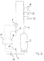
- Figure 1 shows a circuit diagram of a first embodiment of the water supply system according to the invention.
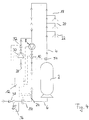
- Figure 2 shows a circuit diagram of a second embodiment of the water supply system according to the invention with return of the circulation line in the cold water line.
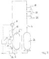
- Figure 3 shows a circuit diagram of a third embodiment of the water supply system according to the invention with two boilers.
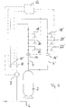
- FIG. 4 shows a circuit diagram of a fourth embodiment of the water supply system according to the invention.
- FIG. 5 shows a circuit diagram of a fifth embodiment with a further circulation line connected in parallel.
- a hot water boiler or boiler 2 which can hold a certain volume of water and heats it by means of an internal heating device.
- the boiler 2 is connected on the output side to a circulation line 4 which is recirculated to the boiler 2.
- connection points for hot water supply lines 18, 20 and 22 are initially provided, through which hot water is removed.
- the circulation line is in the return line behind the connection points for the supply lines 4, a circulation pump 8 is arranged, which is used to circulate the circulation water.
- a solenoid valve 10 is arranged, which serves to close the circulation line. The circulation line flows back into the boiler 2 behind the solenoid valve.
- a cold water line 6 is connected to the inlet side of the boiler 2, through which cold water flows into the boiler 2 after it has been emptied.
- the supply system has the property that immediately after water has been removed from one of the supply lines 18, 20 or 22, the pressure loss transmitted leads to the afterflow of cold water.
- a flow sensor or flow monitor 14 is arranged in the cold water line 6 in front of the connection point of the boiler 2 and serves to detect the flow or flow of the cold water.
- the flow sensor 14 generates a trigger signal when a predetermined limit flow is exceeded, which is transmitted electrically to an electronic timer 12.
- the time switch 12 switches on the circulation pump 8 connected to it.
- the timer 12 opens the solenoid valve 10 connected to it, so that circulation of the circulation water now takes place.
- a delay time is set in the timer 12, which is 1/2 minute to 1 minute. This run-on time elapses after the circulation pump 8 is switched on.
- the circulation pump is switched off and the solenoid valve 10 is closed at the same time. Then the timer 12 is blocked for a certain period of time so that the circulation pump can no longer be switched on during this period.
- the duration is about 1 min.
- the electronic timer 12 has an associated control unit 16 which is only connected to the solenoid valve 10 or a control line to the solenoid valve 10.
- the control unit has the task of keeping the solenoid valve 10 open at a predetermined time of day for a certain period of time, so that a basic circulation takes place during this time due to a gravity flow in the circulation system.
- the control unit 16 thus inhibits a closing pulse of the timer 12, which is given to the solenoid valve 10 by the control line.
- the water supply system works as follows. After opening one of the supply lines 18 to 20, there is a pressure drop in the circulation line 4, which is transmitted directly to the boiler 2. The pressure drop leads to the inflow of cold water through the cold water line 6.
- the flow sensor 14 arranged there detects or measures a flow and generates a trigger signal which is sent directly to the time switch 12 which switches on the circulation pump 8 and opens the solenoid valve 10.
- a pump-driven circulation of the circulation water takes place shortly after the opening of one of the supply lines and provides hot water from the boiler 2 at the connection points for the supply lines 18 to 22 after a short time.
- the cold water initially located in the circulation line below the connection points no longer reaches the supply lines.
- the circulation pump 8 is switched off and the solenoid valve 10 is closed.
- the time required for this corresponds to the run-on time of the timer 12.
- the invention accordingly provides a saving in electricity, since the circulation pump only when water is drawn and only for the necessary Time is running. Furthermore, there is no unnecessary operation of the circulation pump, which in conventional systems leads to the boiler being drained and thus to unnecessary heat loss. This advantage is particularly useful for solar systems because they cannot compensate for the heat loss caused by the circulation at night.
- the second embodiment of the water supply system according to the invention shown in FIG. 2 initially differs from the first embodiment according to FIG. 1 in that the circulation line is not returned to the boiler 2 but to the cold water line 6.
- the junction of the circulation line 4 in the cold water line 6 is located between the flow sensor 14 and the boiler 2. In this way, cooling of the boiler heating water by back-flowing cooled circulation water is avoided immediately.
- a temperature sensor 24, which is connected to the timer 12, is also arranged in the circulation line 4 near the mouth of the cold water line 6. The temperature sensor 24 measures the temperature of the circulation water flowing in the circulation line 4 and supplies the measured value to the timer 12.
- the timer 12 processes the measured value from the temperature sensor 24 in such a way that it switches off the running circulation pump 8 and closes the solenoid valve 10 when the temperature of the circulation water exceeds a predetermined value.
- This limit corresponds to the desired hot water temperature and is around 37 ° C.
- the processing of the measured value in the timer 12 is, however, also dependent on whether a preselectable maximum run-on time has already expired. When this maximum run-on time has expired, the circulation pump 8 is switched off in any case and the solenoid valve 10 is closed in any case.
- the maximum run-on time therefore represents a safety limit for the run-on time for the case that the desired temperature of the circulation water cannot be reached. In this embodiment too, the timer 12 is blocked for a certain period of time after the circulation pump has been switched off, since the circulation water is still hot.
- the third embodiment of the water supply system according to the invention shown in FIG. 3 differs from the embodiment according to FIG. 2 essentially in that a further boiler 26 is arranged in the circulation line 4.
- a double boiler system has the purpose that the first boiler 2 heats the incoming cold water to a preheating temperature with which the water flows into the second boiler 26.
- the heating device arranged in the second boiler 26 now heats the already preheated water by a differential temperature to the desired target temperature.
- the power consumption of the second boiler 26 is therefore lower in comparison than the power consumption of a boiler 2 in an embodiment according to FIG. 2.
- the actual advantage of this arrangement arises when the water in the first boiler 2 of this embodiment is heated by solar energy.
- the boiler 2 is designed, for example, as a solar collector, which preheats the water to, for example, 35 ° C. If such a boiler is equipped with a large volume, for example 500 l, there is the possibility of heat storage even during the night when there is no heating.
- the circulation pump 8 is switched on and the solenoid valve 10 is opened. Due to the pressure difference, preheated water from the first boiler 2 is conveyed to the second boiler 26 and water from the second boiler 26 heated to the desired temperature flows into the circulation line 4 a.
- the temperature sensor 24 in turn ensures that the circulation pump only works until the desired temperature of the circulation water is reached.
- the fourth embodiment of the water supply system according to the invention shown in FIG. 4 differs from the second embodiment shown in FIG. 2 essentially in that a bypass line 28 is connected to the circulation line, which bridges the circulation pump 8 and the solenoid valve 10.
- the bypass line 28 therefore branches off in front of the circulation pump 8 in the flow direction and opens into the circulation line 4 behind the solenoid valve 10 in the flow direction.
- a counter valve 32 configured as a solenoid valve is arranged behind the counter pump 30 and fulfills a function similar to that of the solenoid valve 10.
- the counter pump 30 and the counter valve 32 are connected to the electronic time switch 12. Furthermore, a counter-temperature sensor 34, which is also connected to the electronic time switch 12, is arranged in the circulation line in the vicinity of the outlet from the boiler 2.
- the electronic time switch 12 switches on the counter pump 30 and opens the counter valve 32 if a certain rest period, e.g. 30 seconds has passed in which no water has been removed.
- the activation of the counter pump 30 and the opening of the counter valve 32 leads to the fact that the hot water in the circulation line 4 is conveyed back in the opposite direction to the conveying direction of the circulation pump 8 and is transported back into the boiler 2. In this way it is prevented that the hot water in the circulation line 4 cools down.
- a pump which can be operated in opposite directions is used instead of the circulation pump 8.
- Such a pump can be operated in both directions, for example, by switching four valves.
- a check valve 38 is finally arranged at the entrance of the cold water line 6, which serves to prevent any recoil in the cold water line 6.
- the check valve 38 shuts off.
- a pressure relief valve 36 is connected to the cold water line 6, which opens at an excessive pressure in the cold water line 6.
- FIG. 5 shows a further embodiment of the invention Water supply system with a parallel circulation line 4 'shown.
- This further circulation line 4 ' branches immediately behind the boiler 2 in the direction of flow from the circulation line 4 and opens into the same circulation line 4 in front of the circulation pump 8 again.
- a shut-off valve 10 ' arranged in parallel with the shut-off valve 10' is arranged in the circulation line 4 '.
- the flow sensor 14 'as well as the flow sensor 14 detects a flow or the change in a flow in the circulation line 4' or 4.
- the flow sensor 14 ' is connected to the already mentioned timer 12, which in turn has a control line to the shut-off valve 10' .
- the timer 12 is designed in this embodiment so that it does not detect the flow itself, but a change in the flow in the circulation line 4 '. Since the flow sensor 14 'is arranged in the circulation line, gravity circulation can lead to a basic flow, for example, which should not be interpreted as hot water demand.
- the timer 12 therefore responds only to a positive change, that is to say an increase in the flow in a time interval by a certain amount, in order to switch on the circulation pump 8 and to open the shut-off valve 10 or 10 'located in the corresponding circulation line.
- this embodiment favors a time-controlled gravity circulation only under certain circumstances, since an opening of certain shut-off valves outside of the actual one Demand times can lead to both circulation lines being circulated in another circulation line if there is simultaneous demand, although there is actually only one demand in one circulation line.
- the time-controlled gravity circulation should therefore only be used sparingly and under certain circumstances.
Claims (10)
- Système de distribution d'eau comprenant
une chaudière (2) reliée du côté de la sortie à une conduite de circulation (4) qui revient à la chaudière (2),
une pompe de circulation (4) disposée dans la conduite de circulation (4),
une conduite d'eau froide (6) qui est reliée à un côté d'entrée de la chaudière, et
un capteur de débit (14) disposé dans la conduite d'eau froide (6) respectivement dans la conduite de circulation (4),
qui est couplé à la pompe de circulation (8), le capteur de débit (14) et
la pompe de circulation (8) étant reliés par un interrupteur à minuterie (12) qui met en route et arrête après un temps de fonctionnement la pompe de circulation (8) en fonction de l'écoulement dans la conduite d'eau froide (6) respectivement dans la conduite de circulation (4),
caractérisé en ce que
une soupape d'arrêt (10) couplée à l'interrupteur à minuterie (12) est disposée dans la conduite de circulation (4) et en ce que la soupape d'arrêt (10) est de plus reliée à un organe de commande (16) pouvant ouvrir la soupape d'arrêt en vue d'un écoulement par gravité. - Système de distribution d'eau comprenant une chaudière (2) reliée du côté de la sortie à une conduite de circulation (4), une pompe de circulation (4) disposée dans la conduite de circulation (4), une conduite d'eau froide (6) qui est reliée à un côté d'entrée de la chaudière, et
un capteur de débit (14) disposé dans la conduite d'eau froide (6) respectivement dans la conduite de circulation (4), qui est couplé à la pompe de circulation (8), le capteur de débit (14) et la pompe de circulation (8) étant reliés par un interrupteur à minuterie (12) qui met en route et arrête après un temps de fonctionnement la pompe de circulation (8) en fonction de l'écoulement dans la conduite d'eau froide (6) respectivement dans la conduite de circulation (4),
caractérisé en ce que
une soupape d'arrêt (10) couplée à l'interrupteur à minuterie (12) est disposée dans la conduite de circulation (4), en ce que la conduite de circulation (4) débouche dans la conduite d'eau froide (6) et en ce que la soupape d'arrêt (10) est de plus reliée à un organe de commande (16) pouvant ouvrir la soupape d'arrêt en vue d'un écoulement par gravité. - Système de distribution d'eau selon la revendication 1 ou 2, caractérisé en ce que l'interrupteur à minuterie (12) est bloqué pendant une durée prédéterminée après l'arrêt de la pompe de circulation (8).
- Système de distribution d'eau selon l'une quelconque des revendications précédentes, caractérisé en ce qu'une sonde de température (24) reliée à l'interrupteur à minuterie (12) est disposée dans la conduite de circulation (4), le temps de fonctionnement se terminant lorsqu'une température de l'eau prédéterminée est atteinte dans la conduite de circulation (4).
- Système de distribution d'eau selon la revendication 4, caractérisé en ce que l'interrupteur à minuterie (12) arrête la pompe de circulation (8) après l'expiration d'un temps de fonctionnement maximum réglable, même lorsque la température prédéterminée n'est pas atteinte.
- Système de distribution d'eau selon l'une quelconque des revendications précédentes, caractérisé en ce qu'une autre chaudière (26) est disposée dans la conduite de circulation.
- Système de distribution d'eau selon l'une quelconque des revendications précédentes, caractérisé en ce qu'une conduite de dérivation (28) est reliée à la conduite de circulation (4) qui contourne la pompe de circulation (8) et la soupape d'arrêt (10), en ce qu'une pompe antagoniste (30) qui pompe dans le sens opposé de la pompe de circulation (8) ainsi qu'une soupape antagoniste (32) sont disposés dans la conduite de dérivation (28) qui sont reliées à l'interrupteur à minuterie (12) et en ce qu'une sonde de température antagoniste (34) reliée à l'interrupteur à minuterie (12) est disposée dans la conduite de circulation (4), la pompe antagoniste (30) étant mise en route par l'interrupteur à minuterie (12) et étant arrêtée lorsqu'une température prédéterminée est atteinte dans la conduite de circulation (4) ou après l'expiration d'un temps de fonctionnement maximum réglable.
- Système de distribution d'eau selon la revendication 1 ou 2, caractérisé par une autre conduite de circulation (4′) qui dérive, derrière la chaudière (2) de la conduite de circulation (4) et débouche dans celle-ci entre la soupape d'arrêt (10) et la pompe de circulation (8).
- Système de distribution d'eau selon la revendication 8, caractérisé en ce qu'un autre capteur d'écoulement (14′) et une autre soupape d'arrêt (10′) qui sont reliés à l'interrupteur à minuterie (12), sont disposés dans l'autre conduite de circulation (4′).
- Système de distribution d'eau selon la revendication 8 ou 9, caractérisé en ce que l'interrupteur à minuterie (12) ouvre en fonction de l'écoulement dans l'une des conduite de circulation (4; 4′) la soupape d'arrêt (10; 10′) associée à cette conduite de circulation (4; 4′) et met en route la pompe de circulation (8).
Applications Claiming Priority (2)
| Application Number | Priority Date | Filing Date | Title |
|---|---|---|---|
| DE4138858 | 1991-11-26 | ||
| DE4138858A DE4138858C2 (de) | 1991-11-26 | 1991-11-26 | Warmwasser-Versorgungssystem mit einem Kessel, der mit einer Zirkulationsleitung verbunden ist |
Publications (2)
| Publication Number | Publication Date |
|---|---|
| EP0544207A1 EP0544207A1 (fr) | 1993-06-02 |
| EP0544207B1 true EP0544207B1 (fr) | 1995-10-18 |
Family
ID=6445617
Family Applications (1)
| Application Number | Title | Priority Date | Filing Date |
|---|---|---|---|
| EP92119900A Expired - Lifetime EP0544207B1 (fr) | 1991-11-26 | 1992-11-23 | Système de distribution d'eau |
Country Status (3)
| Country | Link |
|---|---|
| EP (1) | EP0544207B1 (fr) |
| AT (1) | ATE129333T1 (fr) |
| DE (2) | DE4138858C2 (fr) |
Cited By (1)
| Publication number | Priority date | Publication date | Assignee | Title |
|---|---|---|---|---|
| EP3372904A1 (fr) * | 2017-03-09 | 2018-09-12 | Oliver Kuhnt | Installation de circulation |
Families Citing this family (3)
| Publication number | Priority date | Publication date | Assignee | Title |
|---|---|---|---|---|
| EP0626629A3 (fr) * | 1993-05-26 | 1995-02-01 | Mendiguren Santiago Eiguren | Groupe de contrÔle et programmation pour les installations de chauffage à l'eau chaude. |
| DE4339617C2 (de) * | 1993-11-20 | 2003-06-05 | Vortex Gmbh Dt | Rückschlagventil für ein Brauchwasser-Zirkulationssystem |
| DE10208772A1 (de) * | 2002-02-28 | 2003-10-02 | Henke Sass Wolf Gmbh | Steuergerät und Verfahren zur Steuerung einer Umwälzpumpe |
Family Cites Families (4)
| Publication number | Priority date | Publication date | Assignee | Title |
|---|---|---|---|---|
| DE2945568A1 (de) * | 1979-11-10 | 1981-05-21 | Wolfgang Dipl.-Phys. Dr.rer.nat. 5100 Aachen Thiele | Warmwasserversorgungsvorrichtung |
| DE3334103A1 (de) * | 1983-09-21 | 1985-04-04 | Deutsche Vortex GmbH, 4050 Mönchengladbach | Warmwasserversorgungsvorrichtung |
| DE3505191A1 (de) * | 1985-02-15 | 1986-08-21 | Reinhold 6551 Wonsheim Kumpa | Schaltsystem fuer warmwasserversorgungen |
| US4945942A (en) * | 1989-09-29 | 1990-08-07 | Metlund Enterprises | Accelerated hot water delivery system |
-
1991
- 1991-11-26 DE DE4138858A patent/DE4138858C2/de not_active Expired - Fee Related
-
1992
- 1992-11-23 EP EP92119900A patent/EP0544207B1/fr not_active Expired - Lifetime
- 1992-11-23 AT AT92119900T patent/ATE129333T1/de not_active IP Right Cessation
- 1992-11-23 DE DE59204066T patent/DE59204066D1/de not_active Expired - Fee Related
Cited By (2)
| Publication number | Priority date | Publication date | Assignee | Title |
|---|---|---|---|---|
| EP3372904A1 (fr) * | 2017-03-09 | 2018-09-12 | Oliver Kuhnt | Installation de circulation |
| DE102017104947A1 (de) | 2017-03-09 | 2018-09-13 | Oliver Kuhnt | Umwälzanlage |
Also Published As
| Publication number | Publication date |
|---|---|
| ATE129333T1 (de) | 1995-11-15 |
| DE4138858C2 (de) | 1993-11-25 |
| EP0544207A1 (fr) | 1993-06-02 |
| DE59204066D1 (de) | 1995-11-23 |
| DE4138858A1 (de) | 1993-05-27 |
Similar Documents
| Publication | Publication Date | Title |
|---|---|---|
| EP2154436B1 (fr) | Procédé et dispositif pour l'utilisation de chaleur | |
| DE2445905B2 (de) | Warmwasserversorgungsanlage mit thermostatisch geregelter Mischbatterie | |
| DE10318821A1 (de) | Verfahren zur Bereitstellung von warmem Wasser in einer Brauchwasserinstallation und Brauchwasserinstallation | |
| DE4206074A1 (de) | Anordnung zur entnahme von warmem oder heissem brauchwasser von trinkwasserqualitaet | |
| EP0544207B1 (fr) | Système de distribution d'eau | |
| EP0674137A1 (fr) | Système de distribution d'eau chaude à recirculation | |
| DE102006009411B4 (de) | Anlage zum Erwärmen von Trinkwasser und zum Abtöten von Legionellen und sonstigen Keimen | |
| EP0892223A2 (fr) | Dispositif de commande et de régulation pour système de chauffage | |
| EP1170554A2 (fr) | Ensemble et procédé pour préparer de l'eau chaude sanitaire | |
| DE3727442C2 (fr) | ||
| DE10160763A1 (de) | Kühlmittelzirkuliervorrichtung mit automatischem Rückgewinnungsmechanismus | |
| EP1342957B1 (fr) | Méthode et appareil pour contrôler une pompe de circulation | |
| DE19516941C2 (de) | Vorrichtung und Verfahren zur Steuerung der Abgabe von Brauchwasser | |
| AT377598B (de) | Warmwasserleitungssystem | |
| DE202006003226U1 (de) | Anlage zum Erwärmen von Trinkwasser und zum Abtöten von Legionellen und sonstigen Keimen | |
| EP1553353B1 (fr) | Bypass dans un conduit d'arrivée d'un réservoir de réaction | |
| DE2846753A1 (de) | Verfahren und einrichtung zum ein- und ausschalten einer umwaelzpumpe einer heizungsanlage | |
| EP0556736A1 (fr) | Procédé pour la commande d'une chaudière | |
| EP2136146B1 (fr) | Dispositif et procédé de commande du débit d'appareils de débit d'eau potable entraînés de manière solaire | |
| DE3117771C2 (fr) | ||
| EP0346977B1 (fr) | Chauffe-eau | |
| DE1930950A1 (de) | Selbsttaetiger,in Abhaengigkeit von der Stromaufnahme arbeitender Wasserstandsregler fuer elektrisch durch Tauchelektroden beheizte Dampf- oder Warmwasserkessel | |
| AT397425B (de) | Steuerverfahren für eine heizungsanlage | |
| EP3647667B1 (fr) | Chauffe-eau instantané d'eau potable, système de chauffage d'eau potable et procédé de fonctionnement d'un chauffe-eau instantané d'eau potable | |
| DE4300292C2 (de) | Anlage zur Warmwasserversorgung |
Legal Events
| Date | Code | Title | Description |
|---|---|---|---|
| PUAI | Public reference made under article 153(3) epc to a published international application that has entered the european phase |
Free format text: ORIGINAL CODE: 0009012 |
|
| AK | Designated contracting states |
Kind code of ref document: A1 Designated state(s): AT BE CH DE DK ES FR GB GR IT LI LU MC NL PT SE |
|
| RBV | Designated contracting states (corrected) |
Designated state(s): AT CH DE FR GB IT LI SE |
|
| 17P | Request for examination filed |
Effective date: 19931110 |
|
| 17Q | First examination report despatched |
Effective date: 19940117 |
|
| GRAA | (expected) grant |
Free format text: ORIGINAL CODE: 0009210 |
|
| AK | Designated contracting states |
Kind code of ref document: B1 Designated state(s): AT CH DE FR GB IT LI SE |
|
| PG25 | Lapsed in a contracting state [announced via postgrant information from national office to epo] |
Ref country code: GB Effective date: 19951018 Ref country code: FR Effective date: 19951018 |
|
| REF | Corresponds to: |
Ref document number: 129333 Country of ref document: AT Date of ref document: 19951115 Kind code of ref document: T |
|
| REF | Corresponds to: |
Ref document number: 59204066 Country of ref document: DE Date of ref document: 19951123 |
|
| ITF | It: translation for a ep patent filed |
Owner name: STUDIO ING. ALFREDO RAIMONDI |
|
| PG25 | Lapsed in a contracting state [announced via postgrant information from national office to epo] |
Ref country code: SE Effective date: 19960118 |
|
| EN | Fr: translation not filed | ||
| GBV | Gb: ep patent (uk) treated as always having been void in accordance with gb section 77(7)/1977 [no translation filed] |
Effective date: 19951018 |
|
| PLBE | No opposition filed within time limit |
Free format text: ORIGINAL CODE: 0009261 |
|
| STAA | Information on the status of an ep patent application or granted ep patent |
Free format text: STATUS: NO OPPOSITION FILED WITHIN TIME LIMIT |
|
| 26N | No opposition filed | ||
| PGFP | Annual fee paid to national office [announced via postgrant information from national office to epo] |
Ref country code: CH Payment date: 20050513 Year of fee payment: 13 Ref country code: AT Payment date: 20050513 Year of fee payment: 13 |
|
| PGFP | Annual fee paid to national office [announced via postgrant information from national office to epo] |
Ref country code: DE Payment date: 20050523 Year of fee payment: 13 |
|
| PG25 | Lapsed in a contracting state [announced via postgrant information from national office to epo] |
Ref country code: AT Free format text: LAPSE BECAUSE OF NON-PAYMENT OF DUE FEES Effective date: 20051123 |
|
| PG25 | Lapsed in a contracting state [announced via postgrant information from national office to epo] |
Ref country code: LI Free format text: LAPSE BECAUSE OF NON-PAYMENT OF DUE FEES Effective date: 20051130 Ref country code: CH Free format text: LAPSE BECAUSE OF NON-PAYMENT OF DUE FEES Effective date: 20051130 |
|
| PG25 | Lapsed in a contracting state [announced via postgrant information from national office to epo] |
Ref country code: DE Free format text: LAPSE BECAUSE OF NON-PAYMENT OF DUE FEES Effective date: 20060601 |
|
| REG | Reference to a national code |
Ref country code: CH Ref legal event code: PL |
|
| PGFP | Annual fee paid to national office [announced via postgrant information from national office to epo] |
Ref country code: IT Payment date: 20061130 Year of fee payment: 15 |
|
| PG25 | Lapsed in a contracting state [announced via postgrant information from national office to epo] |
Ref country code: IT Free format text: LAPSE BECAUSE OF NON-PAYMENT OF DUE FEES Effective date: 20071123 |